Vgref =VHref. 2- Xt - XDRIp. 2. + Xt -XDRIq. (15). In this paper, the parameter XDR is set to 0.05, selected after preliminary studies. IV. ANALYSIS AND RESULTS.
Reactive power handling by a multi-objective formulation Juan M. Ramirez, Xiomara Gonzalez, and Miguel Medina Centro de Investigación y de Estudios Avanzados del Instituto Politécnico Nacional Guadalajara, Jal., MEXICO. Email: {jramirez, xgonzale, mmedina}@gdl.cinvestav.mx Abstract—In order to attain an optimal operation, this paper proposes the minimization of the reactive power losses and a voltage stability index, taking into account the line drop compensation in the step-up transformers. The application is carried out in an equivalent of the Mexican power system, solved by genetic algorithms. Results are presented showing the advantages of the optimal operation with respect to a nonoptimized nominal condition.
I.
INTRODUCTION
As power systems enlarge, the reactive power compensation becomes more necessary to achieve adequate levels of voltage and transmission capacity. Likewise, it is relevant to reduce losses and the stress on their elements. Thus, an optimal formulation to contribute to attain such purposes may be appropriate. In general, it includes several objective functions, possibly in conflict among themselves. Multi-objective optimization problems are usually solved from the Pareto front [1]. The solutions are a set of non-dominated feasible solutions called the Pareto optimal set [2, 3]. Among the most important problems of the energy generation and transmission systems are the constancy of a voltage profile, the optimal operation, keeping the system’s security [4]. Different methods have been presented in the open research to solve such kind of problems. Two major strategies can be mentioned [4]: •
•
The first strategy is based on the evolutionary techniques [5] as the NPGA method (Niched Pareto Genetic Algorithm) [6, 7], NSGA (Non dominated Sorting Genetic Algorithm) [8, 9], SPEA (Strength Pareto Evolutionary Algorithm) [10], SPEA-II (Improving Strength Pareto Evolutionary Algorithm) [11], an Improved Hybrid Evolutionary Programming Technique [12] and the Ant Colony Optimization Method [13]. The second strategy is based on conventional methods. They include the Gradient-based Method, the Non-Linear Programming (NLP), the Quadratic Programming (QP), the Linear Programming (LP) and the Interior Point Methods [14-18], the Weights Method [19], and the ε-Constraints Method [20].
These conventional methods are based on the global minimum estimation. However, due to difficulties of differentiability, non-linearity, and non-convexity, these methods do not guarantee to reach the global optimum [21]. Moreover, these methods present some inconveniences as the time of execution, problems of convergence, the algorithmic complexity, and the generation of a weak number of nondominated solutions. Due to these inconveniences, the evolutionary algorithms have been accepted as methods to solve optimization problems, thanks to their ability of exploiting huge searching spaces and they do not require a deep knowledge of the problem [4]. In this paper, the problem is formulated by two objective functions. The evolutionary optimization method of solution used is the software NSGA-II [8-9]. II.
FORMULATION
The reactive power and voltage control problem may be stated as an optimal formulation; in this case by two objective functions: (1) reactive power losses, (2) a voltage stability index, subject to some equality and inequality constraints. A. Objective Functions 1) Reactive power losses: The main constraints in power transmission are the high reactive power losses on the highly loaded lines, aspects that reduce the transmission capacity. Therefore, in this paper the minimization of reactive power losses are selected as the first objective function, which is approximated by the following expression [28], Line’s losses: PVAR =
2
cos
(1)
This expression represents the line reactive losses. where Vi and Vj are the sending and receiving voltages, XL is the line reactance, δij is the angular difference between buses i and j.
Losses in the power system: f1 =
where, NT is the number of transformers.
∑nkl 1 P VAR_k
(2)
where nl is the number of lines. 2) Voltage Stability Index: The voltage stability analysis of a power system can be determined by an index of quantifiable voltage stability, which refers to two important aspects: (1) an appropriate index of voltage stability that describes when the system is near of voltage instability, (2) the determination of buses exhibiting weak stability and the involved areas [22]. In the open research there are a variety of indexes that help to assess the steady state voltage stability. In this case, the voltage stability index L-index is used [23]. This index is able to evaluate the steady state voltage stability margin of each bus. The L-index value lies between zero (no load) and one (voltage collapse). This value implicitly includes the load effect. The bus with the highest L-index value will be the most vulnerable, and therefore, this method helps to identify weak areas that require a critical support of reactive power. The Lindex is calculated by the following expression [23], f2 = Lindex = maxj
αL
1-
∑i α Fji Vi G Vj
B. Constraints 1) Equality Constraints: The equality constraints are the balance of the active and reactive power described by the set of power flow equations. They can expressed as follows, PGi -PDi - ∑nj= 1|Vi | Vj Yij cos δi -δj +θij = 0
(4)
QGi -QDi - ∑nj= 1|Vi | Vj Yij sen δi -δj +θij = 0
(5)
where, PGi is the active power generation node, QGi is the reactive power generation node, PDi is the active power load node, QDi is the reactive power load node, and |Yij| is the ij-th element of the bus admittance matrix. 2) Inequality Constraints a) Generators: These restrictions are: generators’ voltage (VGi), active power (PGi), and reactive power (QG), max Vmin Gi ≤ VGi ≤ VGi , i = 1, …, NG
(6)
Pmin Gi
(7)
≤ PGi ≤
i = 1, …, NG
max Qmin Gi ≤ QGi ≤ QGi , i = 1, …, NG
b) Transformers: Tap position T of transformer, Tmin ≤ Ti ≤ Tmax i i , i = 1, …, NT
(9)
(10)
where, NC is the number of switchable sources VAR. d) Load Bus Voltage (VL): max Vmin Li ≤ VLi ≤ VLi , i = 1, …, NL
(11)
where, NL is the number of load nodes. C. Method of solution In summary, the proposed problem is formulated as a nonlinear multi-objective optimization problem, as follows, min f(x) = f1 (x), f2 (x) Subject to equations (4)-(11) where the state vector x, or decision variables, consists of the generating bus voltages VG, the transformers’ tap ratio positions in the on-load tap changers T, and the value of the shunt susceptance at the on-load shunt devices, Yshunt. Therefore, the state vector x becomes: x = VG1 … VGNG , T1 …TNT ,YShunt1 … YShuntN
C
(12)
In this paper, the NSGA-II algorithm (Non dominated Sorting Genetic Algorithm-II) [8, 9, 24] is used to solve the formulation. The algorithm NSGA-II has proven to exhibit a well performance; it is reliable and easy to handle. Pragmatically, it is also one of the most efficient algorithms that have shown better results to solve optimization problems with multiobjective functions in a series of benchmark problems [24, 25]. III.
LINE-DROP COMPENSATION
An important aspect that must be taken into account in order to improve the voltage stability is the voltage drop compensation due to the step-up transformers at generating stations. The high side voltage control (HSVC), which regulates the high voltage side of the step-up transformer, it has been developed without feedback requirements. The HSVC can be attained using only signals provided by the automatic voltage regulator (AVR). This is advantageous since the high side voltage measurement is avoided [26]. The purpose is to maintain a relatively high and flat transmission voltage profile for stressed load conditions (or even for normal conditions). As reported in [27], the benefits by improving the voltage profile of transmission are: 1.
Alleviates generators from operating near limits, allowing for increased reactive power reserves for contingencies;
2.
Reduces transmission I2X reactive power losses and thereby reduces generator reactive outputs;
3.
Decreases I2R heating of transmission lines by a 1/V2 factor.
(8)
where, NG is the number of generators.
Switchable VAR sources: Reactive compensators ≤ QCi ≤ Qmax , i = 1, …, NC Qmin Ci Ci
(3)
where, Vi and Vj are the complex bus voltages, Fji are the coefficients taken from a so-called hybrid matrix [H], which is generated by a partial inversion of the nodal admittance matrix [Y] and describes the system structure. αL and αG indicate the set of consumer’s and generator’s nodes, respectively.
Pmax Gi ,
c) (QC),
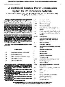
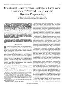
Fig. 1 illustrates the HSVC configuration utilized in this paper. Vgref = VHref 2 -
VH
Xt - XDR Ip
2
+ Xt -XDR Iq
(15)
In this paper, the parameter XDR is set to 0.05, selected after preliminary studies. S. Tr
HSVC Control Block
IV.
VHref
f(Vg, Pg, Qg, Xt, XDR, n)
+
+ + -
AVR Control Block
f(2): Voltage Stability Index (L-index)
Fig. 1. Control system HSVC configuration.
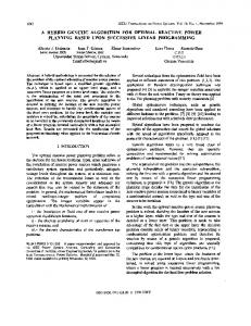
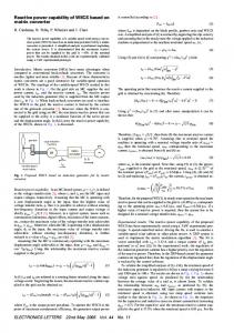
The HSVC’s basic principle is illustrated in Fig. 2, and it is described as follows. The relationship between the voltage in the low side Vg and the high side VH is represented by the following expression, Vg = VH+Xt ·Ig where, Ig =
Pg - jQg Vg
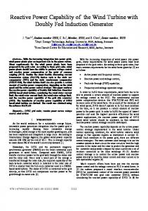
The above described formulation has been applied to a 2212-buses system, corresponding to an equivalent of the Mexican network, solved by the NSGA-II software [24]. For this network, the variables become: A. Objective Functions f(1): Reactive Power Losses
EXC
G
ANALYSIS AND RESULTS
(13)
, Vg is the low side voltage, VH is the
high side voltage, Xt is the reactance of the step-up transformer, Ig is the low side current, Pg is the active power generator, and Qg is the reactive power generator. Here resistance is neglected and a nominal turns is assumed.
B. Decision Variables 165 terminal voltages for the generators of the system under study; 24 tap positions, corresponding to transformers with on-load tap changers; 11 pilot nodes, corresponding to those nodes with on-line shunt susceptance variation capabilities. Thus, this application is constituted by 200 decision variables. In this application, the following parameters are applied: POP = 100 individuals GEN = 20 generations C. Study In this paper, the results for the above-mentioned formulation are exhibited, including the line drop compensation in the step-up transformers. By the evolutionary algorithm [8, 9, 24], many simulations are carried out with different populations (POP) and generations (GEN). Table I summarizes the main results for the minimum demand in year-2011. It has been used an equivalent generator at each plant. The two objective functions were worked simultaneously:
Fig. 2. HSVC concept.
1)
Reactive losses
According to (13), the high side voltage can be controlled to the target value VHref by the generator voltage; that is, by the voltage drop by Xt being completely compensated. However, generator current and reactive power will be imbalanced with multiple generators controlling the same voltage. Therefore, the high side voltage is controlled according to the expression [26],
2)
Voltage stability index L-index
VH where, Iq =
Qg Vg
VHref - XDR·Iq
(14)
, VHref is the target high side voltage, XDR is
the HSVC’s characteristic reactance or voltage droop rate, Ip is the active current generator, and Iq is the reactive current generator. This XDR is necessary for a stable operation among generators parallel-connected. Thus, the terminal voltage Vgref, which determines the high side voltage at the specified voltage VHref, taking into account a parallel operation, becomes:
TABLE I. THE MAIN RESULTS FOR THE MINIMUM DEMAND IN YEAR-2011 Reactive Losses Active Losses Lindex
Base Case 72.15 pu 4.41 pu 0.35
Optimized Case 35.13 pu 4.45 pu 0.32
This Table indicates that in the optimized case a reduction of the reactive losses is attained. The reduction accounts for 51.31%, this corresponds to more than half of the losses presented in the base case. Respect to the voltage stability index, L-index, it has been decreased by 8.6% relative to the base case. In both cases, this value indicates that, for this equilibrium point, the power system is far from voltage difficulties. Tables II-IV present details respect to some variables in some of the most important buses.
TABLE IV. SHUNT VALUE.
Table II shows some of the generators’ voltages stemming from the optimization for this operating condition. Likewise, Table III indicates the tap-position for some transformers with on-line tap changer. Table IV illustrates the optimal shunt value for elements operating in the 400 kV grid and that respond to on-line commands.
Bus Base Case MVAR Optimal Value MVAR 515 -62,01 -76,738 523 -150 227,770 531 -150 156,250 555 -68,02 274,470 556 -100 16,464 583 -63,5 -29,549 581 -63,5 104,940 580 -75 102,880 584 -62 153,200 658 -63,5 193,840 585 -63,5 -43,346
TABLE II. SOME VOLTAGE GENERATION FOR THE MINIMUM DEMAND CONDITION. Bus Voltage Bus Voltage 542 0,992 1140 1,025 570 1,024 1141 1,025 574 1,049 1142 1,025 625 0,997 1143 1,024 630 1,005 1268 1,002 633 1,025 1362 1,024 644 1,025 1666 1,007 651 1,054 1706 0,990 665 1,025 1725 0,991 749 1,025 1796 0,990 769 1,017 1799 0,990 916 1,025 1805 1,021 928 1,008 1884 0,990 1067 1,016 1933 1,025 1104 1,009 1940 1,002 1116 1,024 1983 1,024 TABLE III. TAP POSITIONS. Sending Bus Receiving Bus Optimal Tap Position 515 517 1,012 561 562 1,027 547 548 1,006 550 551 1,033 564 567 1,027 600 601 0,900 600 603 0,900 556 557 0,951 556 558 1,020 523 524 0,982 666 667 1,004 571 572 1,096 589 590 0,901 589 591 0,900 589 592 0,976 613 614 0,936 613 616 0,978 520 521 1,010 605 606 0,961 605 607 1,096 511 514 0,910 637 638 1,100 637 662 0,927 637 640 1,033
V.
CONCLUSIONS
Power systems have elements able to help in controlling a voltage profile and to handle reactive power. Based on an evolutionary algorithm, it is possible to determine the appropriate values for such elements in order to operate in an optimal condition. The optimization problem formulated in this paper was solved by the NSGA-II evolutionary algorithm, which is able to handle multi-objective formulations, showing reliable results over a realistic power system. To define the reference voltage in generators, it is important to take into account the line drop compensation due to the fact that the regulation of the high voltage side in a power station become convenient to reach an improved voltage profile. Active power losses rise slightly in the optimized system because the paper's aim is the reactive power losses’ minimization. A commitment may be attained if the active power losses are taken into account simultaneously. The presented results indicate that the proposed evolutionary algorithm, based on the chosen objective functions, achieve an optimal handling of reactive power by optimizing the decision variables by the minimization of losses of reactive power and voltage stability index of power system. Results indicate that a better use of each element in the power system may be reached. REFERENCES [1]
[2]
[3]
[4]
[5]
W. Stadler. Fundamentals of multicriteria optimization. Stadler, W., Editor, Multicriteria Optimization in Engineering and the Sciences, Plenum Press, New York, 1988. C. A. C. Coello, A. H. Aquirre, and E. Zitzler, “Evolutionary Multiobjective Optimization,” European Journal of Operational Research, Vol.181, No.3, pp. 1617-1619, 2007. H. Wang, C. He, and Y. Liu, "Pareto Optimization of Power System Reconstruction Using NSGA-II Algorithm," in Power and Energy Engineering Conference (APPEEC), 2010 Asia-Pacific, pp. 1-5, 2831 March 2010. M. Belazzoug, and M. Boudour, "FACTS placement multiobjective optimization for reactive power system compensation," in Systems Signals and Devices (SSD), 2010 7th International Multi-Conference on, pp. 1-6, 27-30 June 2010 C. M. M. Fonseca, “Multiobjective Genetic Algorithms with Application to Control Engineering Problems”, PhD thesis,
[6]
[7]
[8]
[9]
[10]
[11] [12]
[13]
[14]
[15]
[16]
[17]
[18]
[19]
[20]
[21]
[22]
[23]
[24]
[25]
Department of Automatic Control and Systems Engineering, University of Sheffield, Sheffield, UK, 1995. J. Hom, N. Nafpliotis, and D. E. Goldberg, "A niched Pareto genetic algorithm for multi objectives optimization", in Proceedings of the First IEEE Conference on Evolutionary Computation, IEEE World Congress on Computational Intelligence, Vol. 1, pp. 82-87, 1994. M. A. Abido, "A niched Pareto genetic algorithm for multi objectives environmental/economic dispatch," Electrical power and energy systems, pp. 97-105, 2003. K. Deb, "Evolutionary Algorithms for Multicriterion Optimization in Engineering Design", Evolutionary Algorithms in Engineering and Computer Science, Chapter 8, pp.135-161, 1999. N. Srinivas, and K. Deb, Multiple Objective Optimization Using Nondominated Sorting in Genetic Algorithms, Evolutionary Computation, vol. 2 (3), pp. 221-248, 1994. E. Zitzler, L. Thiele, "An Evolutionary Algorithm for Multi objectives Optimization: The Strength Pareto Approach", TIK-Report no. 43, 1998. E. Zitzler, M. Laumanns, L. Thiele, "SPEA2: Improving the Strength Pareto Evolutionary Algorithm", TIK-Report no. 103, May 2001. W. Yan, S. Lu, and D. C. Yu, "A Novel Optimal Reactive Power Dispatch Method Based on an Improved Hybrid Evolutionary Programming Technique," Power Systems, IEEE Transactions on, vol.19, no.2, pp. 913- 918, May 2004. T. Bouktir, and L. Slimani, "Optimal Power Flow of the Algerian Electrical Network using an Ant Colony Optimization Method," Leonardo Journal of Sciences, 6, pp. 43-57, 2005. H.W. Dommel, and W.F. Tinny, “Optimal Power Flow Solutions,” IEEE Trans. on Power Apparatus and Systems, PAS- 87, pp 18661876, 1968. K.Y. Lee, Y.M. Park, and J.L Ortiz, “A United Approach to Optimal Real and Reactive Power Dispatch,” IEEE Trans. On Power Apparatus and Systems, PAS-104, pp.1147-1153, 1985. S. Granville, “Optimal reactive power dispatch through interior point methods,” IEEE Trans. on Power Systems, Vol.9, No.1, pp.136-146, Feb. 1994. G.R.M. da Costa, “Optimal reactive dispatch through primal- Dual method,” IEEE Trans. on Power Systems, Vol.12, No.2, pp 669-674, May 1997. M. O. Mansour, and T. M. Abdel-Rahman, "Non-linear VAR Optimization using Decomposition and Coordination", IEEE Trans. Power Apparat. Systems, PAS-103, no. 2, pp. 246-255, 1984. I.P. Abril, and J.A.G. Quintero, "VAr compensation by sequential quadratic programming," Power Systems, IEEE Transactions on, vol.18, no.1, pp. 36- 41, Feb 2003. Y. T. Hsiao, H. D. Chiang, C. C. Liu, and Y. L. Chen, "A Computer Package for Optimal Multiobjective VAR Planning in Large Scale Power Systems", IEEE Trans. Power Systems, 9(2), pp. 668-676, May 1994. S. Ramesh, S. Kannan, and S. Baskar, "Multi-objective evolutionary algorithm based Reactive Power Dispatch with thyristor controlled series compensator," in Power Electronics, Drives and Energy Systems (PEDES) & 2010 Power India, 2010 Joint International Conference on, pp.1-7, 20-23 Dec. 2010 M.V. Suganyadevia, and C.K. Babulal, "Estimating of loadability margin of a power system by comparing Voltage Stability Indices," in International Conference on Control, Automation, Communication and Energy Conservation, 2009. INCACEC 2009, pp.1-4, 4-6 June 2009 P. Kessel, and H. Glavitsch, "Estimating the Voltage Stability of a Power System". IEEE Transactions on Power Delivery, Vol.1, no.3, pp.346-354, July 1986. K. Deb, A. Pratap, S. Agarwal, and T. Meyarivan, “A Fast and Elitist Multi-objective Genetic Algorithm: NSGA-II,” IEEE Trans. on Evolutionary Computation, vol. 6, no. 2, pp. 182-197, Apr. 2002. K. Deb, Multi-Objective Optimization using Evolutionary Algorithms, 1st Edition, John Wiley & Sons (ASIA), Pte Ltd. Singapore, (ISBN 9814-12-685-3), 2001
[26] S. Noguchi, M. Shimomura, J. Paserba, "Improvement to an advanced high side voltage control," Power Systems, IEEE Transactions on, vol.21, no.2, pp. 683- 692, May 2006. [27] G. Andersson, P. Donalek, R. Farmer, N. Hatziargyriou, I. Kamwa, P. Kundur, N. Martins, J. Paserba, P. Pourbeik, J. Sanchez-Gasca, R. Schulz, A. Stankovic, C. Taylor, and V. Vittal, “Causes of the 2003 major grid blackouts in North America and Europe, and recommended means to improve system dynamic performance”, Power Systems, IEEE Transactions on, vol. 20, no. 4, pp. 1922–1928, Nov. 2005. [28] J. Grainger, W. Stevenson. Análisis de sistemas de potencia. Mc Graw Hill. 1997.