Proteus Virtual System Modelling used for microcontroller education Dražen Ćika and Darko Grundler Electrotechnical Department Polytechnic of Zagreb Vrbik 8, Zagreb, 10000, Croatia Phone: (01) 559 5352, (099) 224 7181 E-mail:
[email protected]
Faculty of Textile Technology University of Zagreb Zagreb, 10000, Croatia E-mail:
[email protected]
Abstract - Engineers working in the embedded system design area using micocontrollers need to resolve some issues not found in desktop environment programming. There is often no standard hardware platform for which the software (firmware) is to be developed. Usually both hardware, and firmware need to be designed, and there are many options to be considered when selecting hardware components. Connections to outside world are made through various interfaces, sensors, and actuators. Those components could be unavailable when firmware development is started. Accurate simulation of such systems would save many hours of prototype development. Provided with some application specific virtual instrumentation, we would have complete embedded virtual laboratory at our disposal. In this paper the Proteus Virtual System Modeller (VSM) software from Labcenter Electronics Ltd is used to provide such simulation environment. This software is used to draw the schematic diagram, but the microcontroller drawn is also able to accept, and execute the code produced with independent compiler. It is even possible to connect Proteus VSM with third party software debugger, and watch animated schematic diagram at work as if it was real hardware. As an example, the operation of small 8-bit microcontroller interrupt handler function will be shown in this article, when there are multiple interrupt sources connected to single interrupt line.
I. INTRODUCTION Designing systems with microcontrollers is a process which usually involves creation of both hardware and software. Custom hardware is often needed for several reasons: There are more widely accepted hardware platforms than it would be the case with desktop computers. This makes sense, since embedded devices have found their way into broader range of applications. Some applications are high volume and cost sensitive, other may have very specific power requirements, while some may need input-output interfaces (I/O) rarely found in desktop computers. Reliability of such degree may also be required that it could not be achieved using standard off the shelf boards, or computers. If custom hardware was needed often, it is nearly always the case with the software behind embedded systems. To
make further distinction from desktop systems, we usually refer to their software as firmware. In this article we will present a tool used for embedded system design which is very powerful when used together with traditional software design tools. Using those tools, we can create the complete embedded system prototype in the virtual world, but still use standard electronics parts we are used to, and not only their models which could not be reused for circuit board production. Also, to debug such system a minimum of additional code have to be created, because the virtual hardware cooperates, and communicates with real software development and debugging tools. This makes virtual systems ideal for teaching purposes, specially while teaching general embedded system design principles. In example described here demonstrating shared interrupts on 8051 8-bit microcontroller, it was not necessary to write any code which should be modified, or conditionally compiled if the circuit was built using real components. Also, there were no scripts within the software integrated design environment (IDE) for the purpose of simulating key press, or other external events.
II. LECTURING ON EMBEDDED SYSTEMS How should we approach lecturing embedded systems design? Do we present hardware components first? Should the course in digital, or even analog electronics and interfacing be obligatory? Is this area still primary electrical engineering, or is it more system, and software design? There are no simple answers to those questions, and methodology depends very much on students background and target industry. When we say students, we should note that those students could be experts from other engineering fields in which embedded systems will be deployed. Or they could be software developers with experience from desktop environment used to work in environment with reach processing resources, and object oriented languages. However, they may not be used to interface with sensors, and actuators, or write code close to the hardware level. Even within similar engineering field there could be very different domains of expertise, like for example automotive industry and telecommunications and embedded systems lectures should take this into consideration.
Traditionally embedded systems were small, code written was within the reach of single person, or small development teams, and most embedded software designers came from the field of electronics, and hardware design. It happened simply because those engineers have actually designed the hardware, wrote some device drivers and code used to test the hardware, and than if development team was small they would continue writing application code. It was not very efficient by today standards, and the problem was also that most of those firmware developers never received any formal software design, or project management education. As more standard hardware components became available, embedded systems grew in complexity due to the increased requirements: GUI elements became the norm, communications does not differ much from desktop computers, and software written (or should we still call it firmware?) often grew to hundreds of thousands lines of code. Software design methodology, version management, teamwork, documentation, unit and module testing, system integration, and project management came into focus. It is obvious that we need to cover much wider area when educating embedded system engineers then it would be case twenty, or thirty years ago. With limited time available it is not possible to go into same level of detailed electronic circuits analysis as before. It is also very useful for student to get practical experience, but there is not much time neither to spend building complete hardware prototypes. III. EVALUATION BOARD PROTOTYPING How do we design software for a system involving nonstandard hardware than? And what if this hardware was not jet available when we approached the software design? We would still like to save time, and develop both hardware and firmware independently, and simultaneously if possible. We could use the Evaluation board for the CPU part, and design whatever specific interfaces we need on top of that board. Those interfaces could be as simple as connectors routing all the microcontroller pins out of the board, but we might also need to take care of logic level translation between 5 V, and 3.3 V I/O devices. Other interface might be built within the small prototype PCB area provided by the evaluation board manufacturer. We might even design complete custom application board designed to be stacked up on top of the evaluation board expansion connectors, and use that combination as the final production solution, if quantities were small. In any case, we avoid to reinvent the wheel by designing the CPU board. Even if we did, board manufacturers usually permit us to use their evaluation board schematics diagrams in order to sell more of their components. Evaluation board will also be delivered with code examples, and Board Support Package. With some luck, board manufacturer has already taken care of some of our problems with board interfacing, and maybe we can even use some examples with our application. Main advantage of the evaluation board approach is that it will work at full speed, and we use for the prototype the same microcontroller that we are going to use in target application. This should keep the last minute surprises at minimum.
Main disadvantage of the evaluation board is not the cost (which should be considered) , but the time needed to build the prototype for the rest of application. Also, the software written for the final environment will eventually have to be adapted, since it is not likely that we will finally use exactly the same environment as found on the evaluation board. For students, main disadvantage of evaluation board approach might be the fact it could be destroyed with improper handling, it might be difficult to access internal operation of the board without having expensive instrumentation (e.g. Digital Storage Oscilloscope - DSO, and Logic Analyzer - LA), and so on. Some specific instrumentation (for example communication protocol analyzers like SPI, or I2C bus analyzer) might not be available to students in the real world, and available and easy to use in the simulated environment. Once adapted for certain application or laboratory exercise, evaluation board could not be quickly and simply used for something else. Shortly, it is much easier to experiment within the simulated environment, and learning is all about experimenting. IV. SIMULATING WITH PROTEUS VSM Proteus Ares ™ application designed by Labcenter Electronics company developers is schematic capture program with capability to simulate not only standard analog and digital components, as found in many similar software packages, but it can also simulate the programmable components like microcontrollers, LCD displays with built in graphic controllers, or components with specific communication protocols. Proteus is used for Virtual System Modeling, as stated in the company web site and documentation. It deserves it's name, one could simulate all kind of electronic, and electromechanical components and systems while watching animated behavior on the screen. Motors are spinning, keys are reacting on mouse click visually, but also emit change of resistance to components within simulation environment. LED segments are going bright when specified current starts flowing through them. It is very useful tool in creating animated presentations of circuit behavior to students, even if this was it's only purpose, combined with standard schematic entry, and PCB design functionality. But Proteus VSM is much more than that, as it will be shown. Very interesting characteristics is that all of this circuit animation can also happen under our software control, but our software is stored right in the middle of the schematic diagram. In other words, one can right click with the mouse pointing the microcontroller drawn on the schematics diagram, and select the file somewhere on our disk containing the code executable by that microcontroller. If everything done right, our code compiled with the same tools used for the real microcontroller will execute on the virtual component, but the operation will also be determined with other components on the schematic diagram surrounding the microcontroller. This is impressive by itself, but there are also large number of components that can be used from the library, just like if they were ordered from the electronics components supplier. Where it makes sense, many of them are animated.
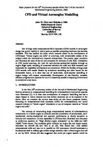
Many standard components are supported, and it is impressive to see the example provided by Labcenter: GNU chess program ported and running on uclinux on the virtual ARM7, drawing the chess board on the touch screen LCD graphic display with industry standard controller. And playing chess, of course. Of course, speed available within the simulation environment depends on the host PC and simulated microcontroller. Simulation will always be accurate, but sense of real time behavior will depend on application requirements. Obviously, it is not the same to use PIC microcontroller with 100 kHz clock, or ARM7 controller running at 70 MHz. Already mentioned chess example does not look bad at all, and display refresh time is acceptable. Our shared interrupt example described later will not have any speed related problems, while for example some MP3 encoding firmware might have. It is also important to mention here that software development tools used in the process are the same as those found in industry environment. For example, when working with 80C51 microcontroller in this article, and also for ARM microcontrollers, our choice was to use the Keil ™ uVision 3 IDE. There is no limit, any tool generating proper output HEX file for ROM or FLASH programming could be used if we only wanted executable code. Proteus VSM schematic could still be animated step by step, or it could run at the full speed supported, but for symbolic debugging we need something more. V. DEBUGGING THE VIRTUAL CIRCUIT It is also possible to connect to Proteus VSM schematic and use it as a target debugged at the source level using the original design environment. Think of it as a virtual target debugger. To Keil uVision in our case, Proteus VSM schematics running the simulation looks just like the real target board with real debugger connected to it. This debugger could reside on the same PC, but it could also be located on the other side of TCP/IP connection. It makes no difference to Keil itself, except for the target IP address used. What we need to setup locally is the Proteus VDM driver for Keil uVision environment. This driver is available on the Labcenter Electronics web site as the Windows ™ executable file. There are actually two drivers, one for 8051, and the other for ARM tool set. Many other integrated design environment are also supported (Microchip MPLAB, Atmel AVR Studio and similar). So what does it look like in practice? Key pressed on Proteus schematic diagram while simulation was running can bring the microcontroller pin low. Microcontroller firmware 'burned' into it's ROM was compiled with debugging symbols still present on our PC. In example shown in Figure 1 there was a Keil debugger running on the left (desktop) with the breakpoint set at the interrupt service routine (ISR) entry. On the right there was a notebook running the Proteus VSM, with DSO set for one shot trigger pulse activated form the ISR.
Figure 1: Remote debugging session using separate hosts
Debugger (PC on the left) has halted execution at the breakpoint within the ISR when pushbutton was pressed within the Proteus VSM on the notebook. Proteus simulation was also halted, scope was still not triggered, and everything was standing still. Proteus VSM simulation and Keil debugger has shown the same value if the program counter (PC) register. Communication also worked the other way around. When Keil debugger on the left has started again, simulation continued on the virtual target just like if it was the real one, and DSO was triggered recording a pulse. No single line of debugging specific code other than DSO trigger signal has been written within the Keil environment. There were also no scripts for simulating the button press, and similar actions usually associated with pure simulator level debugging.
VI. EXAMPLE OF SHARED INTERRUPT Concept and operation of microprocessor interrupts are among most important lessons embedded systems designer should learn. Interrupts are what makes operating systems work. However, generations of desktop programmers, and complex applications with high level of hardware abstraction made interrupts invisible for most developers. Only kernel and device driver programmers are still dealing with interrupts in the world of desktop computers. It is not the case at all in the area of embedded systems programming where every user should be very familiar with the interrupt servicing concepts, and ready to write some ISR if needed. Interrupts are our main, if not only mechanism to process asynchronous events. In very simple cases it might be possible for a program to just wait in a loop for some event, but than everything else would have to wait until expected event occurred. It is not an option if any degree of multitasking is needed, and most embedded devices are expected to do more tasks in the same time. Interrupts could be generated by such simple events as a key press, or very complex events like arrival of Ethernet frame. It does not really matter, we can still group them in several basic categories: periodic or not, level triggered or edge triggered, shared or each having it's own interrupt pin, handled by single ISR, or each having it's own ISR at
separate addresses. As we can see, there are many options to consider. Shared interrupt concept using level triggered interrupts is presented here to make interrupts concept easier for students to understand, and to demonstrate cooperation of Proteus VSM and Keil C51. Figure 2 shows the complete schematic diagram drawn using the Proteus Ares tool.
single microcontroller interrupt input line. Please note how Proteus marked logic high and low level on all pins with red and blue squares. It is very useful visual logic debugging tool which also helped authors finding bug in the interrupt identification algorithm without even resorting to the software debugger. It is like having the logic probe on all pins, active all the time. Each time a pushbutton is pressed, interrupt handler resets flip-flop outputs one by checking if interrupt was deactivated. If so, input checked at the time is identified as the interrupt source, corresponding flag is set and ISR ended. This checking of the interrupt source extends the ISR response time but we cannot detect multiply interrupts faster without allocating more microcontroller I/O lines and connecting them to interrupt sources individually. There is also a side effect that ISR handler response time depends on the interrupt source, based on the order of checking inputs within the ISR code. Trigger signal for DSO is generated so that time spent in ISR could be measured. The full listing of short interrupt routine is shown in the Figure 4.
Figure 2: Schematics diagram for shared interrupts example
Figure 3 shows part of the animated schematic diagram with virtual Digital Storage Oscilloscope (DSO) screen for the case when the pushbutton PB3 is pressed. DSO trigger was set to one shot. As we can also see from the Figure 2, trigger signal is generated by the microcontroller I/O pin P3.7 (controlled within the interrupt service routine shown later), and not directly by the input signal. DSO is thus used to measure the interrupt response time. Please note how LED D3 is lit indicating which button was pressed.
Figure 4: Interrupt Service Routine (ISR)
Figure 3: Shared interrupt – correct response for PB3 press
Principle of operation is visible from the schematic diagram shown in the Figure 2. Of course, we should also look into the program code for full understanding of any embedded system operation. Four active high pushbuttons are connected to inputs of two dual D type Flip-Flops. Flip-Flop output Q will go high if pushbutton was pressed creating rising edge signal. Output can be cleared by microcontroller setting R input low. Flip-Flop outputs are wired to inputs of inverters with open collector outputs which create wired NOR feeding
Main program (not shown here) performs initialization and enters endless loop. It has a simple task of toggling LED when signaled from the interrupt, and it also deactivates reset lines for D Flip-Flops. It follows the proven concept of having the least possible code within the ISR, and handling whatever was possible outside of ISR context, like the toggling LED task here. Only when reset line is deactivated, new press of the same pushbutton could trigger new interrupt. If the pushbutton was not released in the meantime, interrupt will not be triggered (although it is enabled all the time) since there was no rising edge pulse at Flip-Flop CLK input. Benefit of using level triggered interrupts is having more time to identify interrupt source. Interrupt line could stay active until identified, and deactivated by ISR code. Edge triggered interrupt without Flip-Flop could simply go away after triggering ISR, but before ISR could identify it. Thus we would have a ghost interrupt which we could not service.
Shared interrupts together with level active interrupt setup was combination chosen also to demonstrate what will happen if interrupt line was held low too long for some reason? For example, user might keep pressing the key, or the key may fail creating a short circuit In our original schematic nothing serious would happen, but we have made a short circuit between the CLK and D pins just to demonstrate behavior. Figure 5 shows the DSO signal indicating that we are constantly thrown back into ISR as soon as it was serviced, if PB1 is kept pressed. Practically no time is left for executing the main application code.
All mentioned features of Proteus VSM makes it ideal tool for teaching electronic circuits in general and embedded systems particular. Possibility to directly load compiled programs to microcontroller, run the program and visually inspect results are of great assistance during teaching process. Attaching virtual instruments to circuit further improve teaching experience. In addition those characteristics of Proteus VSM makes teaching process more pleasurable which is not negligible benefit. Due to the capability of remote debugging, it could even be possible for students to connect from their homes (one at a time) to the running instance of Proteus virtual prototype on the campus server. It would be interesting for students to run their application which could write the time stamp, some ID or other proof that application was active in the Proteus EEPROM.
REFERENCES
Figure 5: Constant interrupt reentry due to hardware error
VII. CONCLUSION The Proteus VSM is very well suited for educating future engineers in wide area of applications. It is easy to use while teaching basic electric circuits, and it could be also used to demonstrate complex systems involving software design. It is well supported by major embedded system tool vendors (Keil, Microchip, Atmel, IAR) and their debuggers. It's library of parts is open to extensions so that users can add their own parts with full simulation capabilities. Proteus should best be used through several engineering courses, available to every student within a departmental laboratories. Instructor could provide schematics, or just specified parts, and students could build the system per specification. The system build, and programmed (for example, simple garage door opener) could be tested on the virtual prototype, and then retested on the real model, if available.
[1] http://www.labcenter.co.uk/ [2] http://www.keil.com/ [3]High-Speed CMOS Logic Data, MOTOROLA, 1987 [4] Microcontroller Handbook, INTEL, 1986 [5] J. J. Labrosse, “Embedded Systems Building Blocks – Second Edition”, R&D Books, Lawrence, 2000 [6] J. J. Labrosse, “MicroC/OS II, The RealTime Kernel – Second Edition”, R&D Books, Lawrence, 2002 [7] J. Ganssle, “The Firmware Handbook”, Newness, Burlington, 2004 [8] J. Catsoulis, “Designing Embedded Hardware”, O’Reilly, Sebastopol, 2005 [9] M. J. Pont, “Embedded C”, AddisonWesley, London, 2002 [10] M. J. Pont, “Patterns for time triggered embedded systems”, Addison-Wesley, London, 2008 [11] C51 Primer, HITEX, Coventry, 1996 [12] T. Martin, “The Insider's Guide to the Philips ARM 7 Based Microcontrollers”, Hitex, Coventry, 2006 [13] M. Bates, “Interfacing PIC Microcontrollers - Embedded Design by Interactive Simulation”, Elsevier, Oxford, 2006