of IRE 30, 144â150. [17] Bracewell, R. N. 1983. Discrete Hartley transform,. Journal of Opt. Soc. America. [18] Bracewell, R. N. 1984. The fast Hartley transform, ...
International Journal of Computer Applications (0975 – 8887) Volume 97– No.18, July 2014
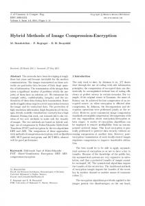
Provenience of Hybrid Transform for Image Compression using Extended Huffman Compression Anu Jain
Alok Jain
Electronics and communication department, Samrat Ashok Technological Institute, Vidisha, M.P, India
Electronics and instrumentation department, Samrat Ashok Technological Institute, Vidisha, M.P, India
ABSTRACT Image compression is a technique to reduce irrelevance and redundancy of the image data in order to be able to store or transmit data in an efficient form. This paper presents a peculiar Hybrid Transform genesis technique for image compression using two orthogonal transforms. The concept of hybrid transform is to combine the attributes of two different orthogonal transform wavelet to attain the vitality of both the transform wavelet. Discrete Cosine transform, Discrete Hartley transform, Discrete Walsh transform and Discrete Kekre Transform all are lossy compression techniques has been used. Also introduced a combination of Huffman and Run length Encoding techniques referred here as Extended Huffman coding which is lossless compression techniques to enhance compression ratio. The result has shown that hybrid transform performance is better than wavelet transforms.
General Terms Hybrid wavelet transform, Orthogonal transform, Extended Huffman coding, Run length encoding.
Keywords Discrete Cosine Transform (DCT), Discrete Walsh Transform (DWT), Discrete Hartley Transform (DHT), Discrete Kekre Transform (DKT), Image compression.
1. INTRODUCTION The advent of high speed computing devices and rapid development in the field of communication has created a tremendous opportunity for various computer based image applications. The amount of data required to store a digital image is continually increasing and overwhelming the storage devices. Therefore, it is required to store images using lesser number of bits than its original size. Image compression deal with this problem. It reduces the number of bits required to represent the image. Hence, reduction in file size allows more image to be stored in a given amount of memory space. It also reduces the time required for the image to be sent over the internet or downloaded from web pages. There are two types of compression methods: lossless compression and lossy compression. The lossless image compression preserves exact data of the original image. Lossless compression techniques are used where reconstruction quality of data is of utmost importance. The lossy compression will not preserve the absolute data content of the original image but preserves some specified level of image quality. It rely on the conception of compromising the accuracy of reconstructed image in order to reinforce the compression ratio. If the resulting distortion is endurable the increase in compression can be significant. Therefore, lossy compression is frequently used as compared
to lossless compression. The measure of image compression achieved is defined as compression ratio. Generally used lossy compression technique are Transform Coding such as Discrete Cosine Transform (DCT) used in JPEG and Wavelet Transform used in JPEG2000[1]. Transform coding technique is based on modifying the transform of an image. Here, reversible linear transform is used to map image into a set of transform coefficients and then these coefficients are quantized and coded. In transform coding initially DCT was popular. It separates an image into different frequency component. Low frequency component provides high energy compaction as compared to high frequency component, therefore they are discarded. Elimination of these high frequency components provides the transformed image with sparse low frequency component. Image reconstructed from these sparse low frequency elements is compressed image without ruining much data content in original image. Since last two to three decades wavelet transform is adopted for enormous applications, often replacing widely used Fourier Transform. Wavelet Transform provides an approach to analyze such data. An important property of wavelet is its Multiresolution capability which helps to view the image at different scales [2-4]. Recently Hybrid Technique is in progression, in which one transform is combined with another transform to amalgamate the advantages of both transforms [5-7]. Initially, Haar Wavelet were focused and widely used for compression [8]. In recent literature [9] wavelets of other orthogonal transforms have been introduced. These transforms include Walsh[10], DCT [ 11,12], Kekre [13-15], and Hartley Transform [16-18] are proposed. The wavelet transform in various applications have performed better than their respective orthogonal transform. This paper presents the inventive Hybrid Transform genesis methodology, which generates Hybrid transform of any two orthogonal transform. The concept behind using hybrid wavelet transform is to exploit the strength of both the transform wavelets. Here, hybrid transform is generated using Discrete Walsh Transform (DWT), Discrete Cosine Transform (DCT), Discrete Hartley Transform (DHT) and Discrete Kekre Transform(DKT) [13]. The another objective of this work is to improvise the compression ratio. Therefore, a combination of two lossy compression method viz., Huffman coding and run length encoding is used. Huffman coding and run length encoding are applied parallely on two different channels on symbols or group of bits rather than single bit. Encoded bits obtained after run length encoding are again coded using Huffman coding. Encoded bits from both the channels are combined to obtain encoded bits for reconstructed image. This is referred here as Extended
21
International Journal of Computer Applications (0975 – 8887) Volume 97– No.18, July 2014 Huffman Compression [19,20]. The experimental results convince that the hybrid transforms are better than their wavelet transforms and due to encoding a higher compression ratio is achieved.
2. PROPOSED METHODOLOGY In proposed technique the concept is to generate hybrid transform from two orthogonal transforms. Schematic diagram of process followed is shown in Figure 1.
Compression Ratio and Mean square error are calculated by using following formulae’s(2)
Where, represents number of bits in original image. represents number of bits in reconstructed image which is obtained after encoding. represents compression ratio after encoding. (3) where, is mean square error before encoding, M×N represents number of rows and columns, represents reconstructed image, F(i,j) represents original image.
2.1 Generation of Hybrid Transform: Let two orthogonal transform matrices A of size MxM (as shown in Figure 2) and B of size NxN (as shown in Figure 3), Hybrid transform matrix T of size MNxMN is generated from orthogonal transform matrix A and B. For example, from orthogonal transform matrix A of size 32x32 and B of size 8x8 , Hybrid transform matrix of size 256x256 is generated. The first N rows of wavelet transform matrix is generated by multiplying each column of matrix B with each coefficient of the first row of matrix A. similarly for next N rows, second row of A is appended with zeros and then it is shift rotated. Similar procedure is repeated for remaining rows of A from third row onwards. This entire procedure is shown in Figure 4 [13].
Fig 1: Schematic diagram of proposed methodology
Consider image ‘I’ of size 256×256. If image is coloured, Convert it from RGB (Red,Green, Blue) format to Gray. For gray image no conversion is required. Hybrid Transform is applied on image. Transformed image of ‘I’ is obtained as F(i,j) = [T]*[I]*[T]t ,where [T] is Hybrid transform matrix and [T]t is transpose of hybrid transform matrix generated using two orthogonal transforms. All coefficients of transformed image lesser than threshold α are mapped to zero. Reconstructed image F(׳i,j) is obtained by applying Inverse Hybrid wavelet Transform. Compression ratio is calculated by using the following formula(1)
A=
Fig 2: M×M Orthogonal matrix A
B=
Fig 2: M×M Orthogonal matrix A
where represents number of bits in original image ‘I’. represents number of bits in reconstructed image ‘F(׳i,j)’. represents compression ratio before encoding.
Bits of reconstructed image are quantized and encoded using Extended Huffman compression technique. Image is reconstructed after encoding by applying Inverse hybrid transform.
22
International Journal of Computer Applications (0975 – 8887) Volume 97– No.18, July 2014
× first block of B
…
× last block of B
…
T=
0
0
0
0
0
0
0
… 0
0
…
0
× first block of B 0
…
× last block of B
0
…
0 0
0
0
0
0
0
0
0
0
…
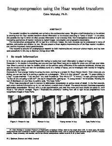
Both colour and black & white images are tested. The size of each image is of 256×256. On each image all four wavelet transform and hybrid wavelet transform are applied. After that extended Huffman coding is applied and performance parameters are calculated before encoding as well as after encoding. Mean square Error and Compression Ratio are the parameters used to evaluate and compare the performance as discussed in previous section. Figure 7, 8 and 9 have shown the compression of pepper image for various hybrid transform with respect to 95%, 90% and 85% of data compression. The quality of image after compression is quite acceptable as negligible distortion is observed in original and compressed image at 95% of data compression.
0
Fig 4: Generation of Hybrid transform T from orthogonal transforms A and B.
2.2 Extended Huffman Compression Technique Flowchart of extended Huffman Compression is shown in Figure 5.
(a)
(b)
(c)
(d)
Fig 6: set of six images of different classes used for experimental purpose namely- (a) brandy rose (b) pepper (c) lena (d) circuit
Original image
95% Data compression
Fig 5: Flow chart of Extended Huffman coding Before encoding quantization is applied. In quantization compression is achieved by compressing a range of values to a single quantum value. Since the given number of bits in the stream is reduced, the stream becomes compressible. After quantization bits are grouped together to form symbols. On these symbols Huffman coding and run length encoding is applied parallel. To Run length encoded bits again Huffman coding is applied. Encoded bits from both the channels are combined to form encoded bits of reconstructed image.
3. EXPERIMENTS AND RESULTS The set of four images are used for proving the caliber of Hybrid Transform technique. Figure 6 shows the set of images used in this experimental work.
90% Data compression
85% Data compression
Fig 7: shows the compression of pepper image using DCT_DHT with respect to 95%, 90% and 85% of data compression.
23
International Journal of Computer Applications (0975 – 8887) Volume 97– No.18, July 2014
DCT WAVELET
DCT_DWT
DCT_DHT
DCT_DKT
20
Original Image
95% Data Compression
Mean Square Error
18 16 14 12 10 8 6 4 2 0 95% 90% Data Compression
85% Data Compression
Fig 8: shows the compression of pepper image using DCT_DKT with respect to 95%, 90% and 85% of data compression.
90%
85%
Percentage of Data compressed Fig 10: Performance comparison of image compression using cosine wavelet transform(DCT WAVELET) and hybrid wavelet transform of DCT taken with Walsh (DCT_DWT), Hartley (DCT_DHT) and Kekre transform (DCT_DKT) for 95% to 85% of data compression for Pepper Image.
DWT WAVELET
DWT_DCT
DWT_DHT
DWT_DKT
95% Data Compression
Mean square error
60 Original Image
50 40 30 20 10
90% Data Compression
85% Data Compression
Fig 9: Shows compression of pepper image using DCT_DWT with respect to 95%, 90% and 85% of data compression. Figure 10, 11, 12 and 13 shows the mean square error differences of original and compressed image pairs plotted against percentage of data compression for 95%, 90% and 85% for image compression done using Hybrid transforms and wavelet transforms.
0 95% 90% 85% Percentage of Data compressed Fig 11: Performance comparison of image compression using walsh wavelet transform(DWT WAVELET) and hybrid wavelet transform of DWT taken with Cosine (DWT_DCT), Hartley (DWT_DHT) and Kekre transform (DWT_DKT) for 95% to 85% of data compression for Pepper image.
24
International Journal of Computer Applications (0975 – 8887) Volume 97– No.18, July 2014
DHT WAVELET
DHT_DCT
DHT_DWT
DHT_DKT
35 Mean square error
30
The mean square error values are considered to be minimum. The compression ratio is another important parameter to compare the performance is given in Table 1,2,3 and 4. Parameters used are- CR1 is compression Ratio before encoding, CR2 is compression ratio after encoding. Transform for which mean square error is minimum and compression ratio is maximum will be considered as best. Table 1. shows Compression ratio for DCT Wavelet and its Hybrid transform before and after encoding
25 20
TRANSFORM USED
15
95%
90%
85%
95%
90%
85%
DCT WAVELET
4.3
3.8
3.52
30.2
27.4
26.5
DCT_DWT
4.1
3.5
3.1
21.6
16.3
15.1
DCT_DHT
4.3
3.7
3.5
37.3
33.8
32.9
DCT_DKT
4.3
3.8
3.5
41.7
38.1
37.1
10 5 0 95% 90% 85% Percentage of data compressed
Fig 12: Performance comparison of image compression using Hartley wavelet transform(DHT WAVELET) and hybrid wavelet transform of DHT taken with Cosine(DHT_DCT), Walsh (DHT_DWT) and Kekre transform (DHT_DKT) for 95% to 85% of data compression for Pepper Image. DKT WAVELET
DKT_DCT
DKT_DWT
DKT_DHT
Table 2. shows Compression ratio for DWT Wavelet and its Hybrid transform before and after encoding TRANSFORM USED
90
Mean square eror
80
95%
90%
85%
95%
90%
85%
DWT WAVELET
4.3
3.8
3.5
34.1
30.6
29.6
70 60
DWT_DCT
4.3
3.8
3.5
26.1
23.9
23.1
DWT_DHT
4.1
3.5
3.1
20.5
15.1
13.7
DWT_DKT
4.1
3.5
3.2
23.5
17.5
16.2
50 40 30 20 10
Table 3. shows Compression ratio for DHT Wavelet and its Hybrid transform before and after encoding
0 95%
90%
85%
Percentage of Data compressed Fig 13: Performance comparison of image compression using Kekre wavelet transform(DKT WAVELET) and hybrid wavelet transform of DKT taken with Cosine (DKT_DCT), Walsh (DKT_DWT) and Hartley transform (DKT_DHT) for 95% to 85% of data compression for Pepper image. It is depicted from Figure 10, 11, 12 and 13 that the best performance in terms of mean square error is given by DCT_DKT ( hybrid transform of cosine transform and kekre transform) followed by DCT_DWT and DCT_DHT (Hybrid transforms of cosine transform taken respectively with Walsh and Hartley transform).
TRANSFORM USED 95%
90%
85%
95%
90%
85%
DHT WAVELET
4.3
3.7
3.5
36.1
32.2
31.1
DHT_DCT
4.3
3.8
3.6
38.1
35.6
34.8
DHT_DWT
4.3
3.8
3.5
39.1
35.9
34.9
DHT_DKT
4.3
3.7
3.5
35.7
31.1
29.9
25
International Journal of Computer Applications (0975 – 8887) Volume 97– No.18, July 2014 Table 4. shows Compression ratio for DKT Wavelet and its Hybrid transform before and after encoding TRANSFORM USED 95%
90%
85%
95%
90%
85%
DKT WAVELET
4.3
3.8
3.6
39.1
36.4
35.6
DKT_DCT
4.3
3.8
3.5
22.5
19.1
18.3
DKT_DWT
4.3
3.88
3.6
36.3
34.1
33.2
DKT_DHT
4.3
3.6
3.3
21.5
17.1
15.9
using Wavelet Pyramids of Walsh, Haar and Kekre Transforms, International Journal of Computer Applications , 1-8. [7] Kekre, H.B., Thepade S.D., and Maloo, A., 2010. Face Recognition using Texture Features Extracted from Walshlet Pyramid, ACEEE International Journal on Recent Trends in Engineering and Technology (IJRTET). [8] Kekre, H.B., Thepade S.D., and Maloo, A., 2010. Face Recognition using Texture Features Extracted from Haarlet Pyramid, International Journal of Computer Applications (IJCA), 41-45. [9] Kekre, H.B., Sarode ,T. and Natu, p. 2013. Image Compression based on Hybrid wavelet transform generated using orthogonal component transform of different sizes, International Journal of soft computing and Engineering.
From Table 1,2,3 and 4 it is observed that maximum compression ratio is obtained for DCT_DKT (Hybrid transform of Cosine and Kekre transform) followed by DHT_DKT (Hybrid transform of Hartley and Kekre transform).
[10] Walsh, J. L., 1923 . A Closed Set of Orthogonal Functions, American Journal of Mathematics, 5-24.
4. CONCLUSION
[12] Chen, W., Smith, C. H., and Fralick, S. C. 1977. A Fast Computational Algorithm For The Discrete Cosine Transform, IEEE Transaction Communications,10041008.
In this paper, prevenient concept of the hybrid transform using two orthogonal transform for image compression using extended Huffman coding is proposed. The hybrid transforms are generated using DCT, DWT, DHT and DKT. From experimental results, inferences has been drawn that the hybrid transform are better than their respective wavelet transforms. Hybrid transform of Discrete cosine transform with Discrete Kekre Transform (DCT_DKT) has given best performance in terms of both MSE and Compression Ratio. The experimental results prove that hybrid Transforms are better in performance as compared to wavelets of orthogonal transform.
5. REFERENCES [1] Kumar, S. and Sood, V . 2012. Quality Assessment of colour image compression using Haar Wavelet Transform, International Journal of Engineering Trends and Technology, 266-269. [2]
Kekre, H.B., Sarode ,T., and Natu, p. 2013. Image Compression Using Real Fourier Transform, Its wavelet Transform and Hybrid Wavelet Transform, International Journal of Advanced Computer science and Application.
[3] Kumar, V.V.S and Reddy, M.I.S. 2012. image compression technique by using wavelet transform, journal of Information Engineering and applications. [4] Nadenau, M. J., Reichel, J., and Kunt, M. Wavelet Based Colour Image Compression: Exploiting the Contrast Sensitivity Function, IEEE Transactions Image Processing. [5] Kekre, H.B., Thepade S.D., Comparison of Haar Wavelets Storing Colour Information International Journal of (IJCA),32-38.
and Parkar, A. 2010. A and Kekre‟s Wavelets for in a Greyscale Image, Computer Applications
[11] Ahmed, N., Natarajan, T., and Rao, K. R. 1974. Discrete Cosine Transform, IEEE Transaction Computers, 90-93.
[13] Kekre, H.B., Sarode ,T., and Thepade, S.D. 2011. Inception of hybrid wavelet transform using two orthogonal transform and it’s exertion for image compression, International journal of computer science and information security. [14] Kekre, H.B., and Thepade, S.D. 2009. Image Retrieval using Non-Involutional Orthogonal Kekre’s Transform, International Journal of Multidisciplinary Research and Advances in Engineering (IJMRAE), 189-203. [15] Kekre, H.B., Thepade, S.D., Athawale, A., Anant, S., Prathamesh, V. and Suraj, S. 2010. Kekre Transform over Row Mean, Column Mean and Both using Image Tiling for Image Retrieval, International Journal of Computer and Electrical Engineering (IJCEE), 964-971. [16] Hartley, R. V. L. 1942. A more symmetrical Fourier analysis applied to transmission problems, Proceedings of IRE 30, 144–150. [17] Bracewell, R. N. 1983. Discrete Hartley transform, Journal of Opt. Soc. America. [18] Bracewell, R. N. 1984. The fast Hartley transform, Proc. of IEEE 1010–1018. [19] Singh, H. and Sharma, S. 2012. Hybrid Image Compression using DWT, DCT & Huffman Encoding Techniques, International Journal of Emerging Technology and Advanced Engineering. [20] Grewal. R.K. and Randhawa, N. image compression using Discrete cosine Transform & wavelet transform, International Journal of Computing & Business Research.
[6] Kekre, H.B., Thepade S.D., and Maloo, A., 2010. Performance Comparison of Image Retrieval Techniques
IJCATM : www.ijcaonline.org
26