2014 IEEE/ASME International Conference on Advanced Intelligent Mechatronics (AIM) Besançon, France, July 8-11, 2014
Pulse-Width-Modulated Charging of Ionic and Capacitive Actuators Indrek Must, Friedrich Kaasik, Inga Põldsalu, Lauri Mihkels, Urmas Johanson, Andres Punning, and Alvo Aabloo
Abstract—We report on using a pulse-width-modulated (PWM) signal for driving the ionic electroactive polymer (IEAP) actuators. The traditional approach for driving the IEAP actuators involves generation of complex analog signals. The proposed control method is substantially different: a digital PWM driving waveform is applied using an H-bridge driver. The two outputs of the H-bridge driver are switched between three states—they are either connected to the positive or negative power supply terminal, or disconnected, with a highimpedance output. An H-bridge can also be used for shortcircuiting of the actuator, in turn improving the powerefficiency of the IEAP actuator. This control method is particularly beneficial in applying IEAP actuators in soft robotics.
I. INTRODUCTION Ionic electromechanically active polymer (IEAP) actuators have been considered as promising materials for biomimetic robotic applications since the beginning of their development.[1] The IEAP-based microrobots are light in weight, soft, compliant, and noise-free [2, 3]. Therefore, they find potential use in rescue work in disaster zones, civil or military surveillance, aerospace engineering [4], or in space missions [5]. In comparison with other smart electrically actuated materials, the IEAPs have considerable advantages over other smart electrically actuated materials. These soft actuators can be easily miniaturized and fabricated in an arbitrary shape even using existing printing technologies [6]. The IEAP actuators are advantageous for soft robotic applications especially due to their softness (elastic modulus below 1 MPa), physical compliance to the surrounding environment, and large electrically-induced deformations. Strain as much as over 50% have been demonstrated on a linear IEAP actuator [7]. On the other side, the soft IEAP actuators are not the favorable choice to be applied in applications that require precise control over the exact position – the “hard” actuators are more suitable for this purpose. Consequently, concerning the particularly beneficial applications for the soft IEAP actuators, the maximum actuation speed of the IEAP actuators is expected * This work was supported by the Estonian Science Foundation grant no. 8553, by targeted financing SF0180008s08 from the Estonian Ministry of Education, by Institutional Research Funding project IUT20-24 from Estonian Research Council. The authors acknowledge support from the Tiger University Program of the Information Technology Foundation for Education, the Estonian Doctoral School in Information and Communication Technology, and the graduate school ‘Functional materials and technologies’. Intelligent Materials and Systems Lab (http://www.ims.ut.ee), University of Tartu, Nooruse 1, Tartu 50411, Estonia E-mail:
[email protected]
978-1-4799-5736-1/14/$31.00 ©2014 IEEE
to be more critical than the capability for accurate positioning. To date, plenty of proof-of-concept microrobots have been developed by various research groups. For example, IPMC-driven underwater robots inspired by, for example, rays [8], jellyfish [9], stalked protozoa [10], insects [11], or snakes [12], have been proposed. The IEAP actuators employed in such visionary robots are commonly driven by rectangular or sinusoidal input voltage. However, in the realworld microrobots, the successful driving electronics must be the simplest in construction, the cheapest in prize, the smallest in dimensions, and lightest in weight. In this work we focus on the choice of the most practical driving signal and give suggestion on the design of driving electronics for the IEAPs. II. PROPOSED SOLUTION FOR DRIVING IEAP ACTUATORS In this work, a simple and effective solution is proposed for driving IEAP actuators. A solution that is commonly used in driving conventional electromagnetic actuators is applied on an IEAP actuator. The pulse-width modulated (PWM) driving is generated by a microcontroller and amplified by an H-bridge. The congruence between the IEAP characteristics and the proposed control signal is explained as follows. A. PWM Driving Signals In the previous works on IEAP actuators, either only voltage on the IEAP terminals is controlled [13, 14], or, alternatively, the electric current is controlled by changing the level of the terminal voltage [15]. Generation of complex analog voltage signals with microcontrollers is a fairly inefficient approach, due to the requirement for external digital-analog converters and blocks for current amplification. At this point, the advantages of PWM driving signals are revealed. In this work, the input (terminal) voltage was held constant and was not controlled. Instead, the time-averaged current was controlled by changing the PWM duty cycle. PWM is a modulation technique that conforms the pulse with duration Ta every period TPWM. The term “PWM duty cycle” is defined as Ta/TPWM. In particular, the PWM signals are advantageous for driving devices with mechanical inertia such as electric motors or solenoids, but find use also in a variety of other uses where control of electric current is required. In the case of IEAPs, the counterpart to the mechanical inertia is the IEAP’s extremely high electrical capacitance. The distinctive property of the IEAP actuators in comparison with the other soft polymeric actuators is their
1446
extremely low driving voltage – commonly in the range of 0.1–5 V. This is the very same voltage range as used to power contemporary microelectronics – 3–5 V. As a rule, the stroke of the IEAP actuator is proportional to its charging level [16]. The charging level, in turn, is proportional to the open-circuit potential on the IEAP electrodes. In order to obtain the maximal stroke and force, the applied voltage should be as high as possible. On the other hand, the voltage applied to the electrodes should not exceed a certain voltage limit, defined by the electrochemical window of the electrolyte used in the IEAP laminate. In this work, we demonstrate that the open-circuit potential on the IEAP electrodes and the voltage applied between the terminals of an IEAP may differ to a large extent. Therefore, it is possible to apply input voltages much higher in amplitude than the IEAP’s maximum allowed open-circuit potential. In the field of IEAPs, PWM control has been previously applied by Shoji et al. on ionic polymer-metal composite (IPMC) actuators to achieve a better control over the force and displacement [17]. Shoji, however, used a PWM control signal which is substantially different from the signal used in this work. In the driving signal used by Shoji, the control voltage alternates between the maximum voltage (2 V) and the short-circuit condition. In such a way the IPMC is charged and discharged during each PWM period. The total accumulated charge is related to the PWM duty cycle, but the power losses increase inverse proportionally with respect to the duty cycle. Obviously, the power-efficiency of such driving signal is low. Moreover, in the Shoji’s work, the PWM signal has an extremely low frequency – in the range of only 2–100 Hz, causing vibrations of the actuator. This behavior is assumedly expendable and does not convey the essence of the PWM signal – current control.
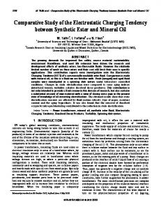
demonstrate the performance and energetic efficiency of the PWM driving signal. III. EXPERIMENTAL A. Actuator An IEAP actuator with non-Faradaic carbonaceous electrodes and with ionic liquid as electrolyte is used. The actuator was put into practice in a cantilever configuration – the input signal was applied to its rigidly clamped end. B. PWM Generation PWM input signal was generated using a custom-made electronic circuit, readily applicable for any potential realworld application that incorporates the IEAPs. The experimental set-up is depicted in Figure 1. The circuit is based on an Atmel ATTINY13A microcontroller. The microcontroller has two dedicated PWM outputs. These outputs can be programmatically connected to either positive or negative terminal of the power supply, or switched between these two voltages using hardware-PWM. The output current is amplified using a Texas Instruments DRV8837 H-bridge driver IC. The outputs of the driver are connected to either positive or negative terminal of the power supply, depending on the signal level in its input ports. An important feature of this H-bridge IC is the optional state with high impedances at both output channels.
B. H-Bridge Drivers The maximum output current of the microcontroller is too low for driving the IEAP actuators directly. An H-bridge can be used to amplify the output current. The advantage of the H-bridge driver driven by PWM control signal is its power-efficiency, as only switching action is required by an H-bridge circuit. The on-resistance of the MOSFET transistors in the H-bridge driver increase with decreased operating voltage, but the typical operating voltage of the IEAP actuators still falls into the same range with the typical voltage used to drive, for example, DC motors. Hence, Hbridge drivers optimized for this voltage range are already widely commercially available. In this work, we specify the peculiarities of using an Hbridge to drive IEAP actuators. By using an H-bridge, it is possible to switch the input of the IEAP actuator between four states: the inputs are connected either to the positive or negative terminal of the power source, are short-circuited, or have high impedance. The advantageous option of the used H-bridge circuit is the possibility of short-circuiting the IEAP on demand. During short-circuiting, the electric current, consumed by the actuator from the power source, is zero, in spite of electric current flowing between the actuator’s electrodes. The presented comparison of an actuator driven with PWM and sinusoidal voltage
Figure 1. The experiment set-up for PWM driving and measuring the IEAPs.
C. Sinusoidal Input For a reference, we used sinusoidal input signal. The sinusoidal input voltage of appropriate amplitude was generated using a National Instruments’ PCI-6036E DAQ device and the electric current was amplified using a custommade current booster based on an OPA548 op-amp. The outputs of the op-amp were directly connected to the IEAP terminals.
1447
D. Electrical and Electromechanical Measurements The voltage at the input terminals of the IEAP actuator as well as the electric current consumed by the H-bridge circuit were measured using a National Instruments’ PCI-6036E DAQ device. The current consumption of the IEAP was calculated straightforwardly – by subtracting the current consumption of the system with the IEAP disconnected. The blocking force was measured by attaching an ADInstruments MLT0202 isometric force transducer to the free end of the cantilevered actuator. The free-bending curvature was determined using image analysis. The actuation was recorded using a DMK 22BUC03 USB camera. The curvature of the actuator was extracted using the National Instruments’ Labview programming environment.
3 gives a corresponding course of voltage between the terminals of the IEAP actuator during a similar working cycle. The open-circuit potential of the IEAP actuator rises only up to 1 V as a result of 10-s charging phase. The IEAP was driven thorough a H-bridge using a bipolar PWM signal of constant period and frequency. The duty cycle of the PWM signal determines the time-averaged charging current, i.e. the amount of charge injected to the IEAP during one charging cycle. Figure 2 shows that in a 10s timeframe, the time-averaged charging current drops only by 20%.
IV. RESULTS In the performed experiments, the IEAP actuator was driven by PWM control waveform generated using the microcontroller. Sinusoidal driving signal was used as a reference. A. Control Waveform Using H-bridge circuit to drive the IEAP allows forming a driving waveform that combines the following phases: 1. Charging phase. The voltage on IEAP terminals is switched between the power supply voltage and the IEAP open-circuit voltage at the PWM sampling frequency.
Figure 2. Current consumption in case of PWM input.
2. Short-circuiting phase. Both terminals of the IEAP are connected to equal potentials. If the IEAP is charged at the beginning, it is discharged during the short-circuiting phase. This in turn also results in actuation towards the position corresponding to the uncharged state. 3. Holding phase. The outputs of the driver are switched to the high-impedance state. This phase holds the IEAP in a fixed position. However, the back-relaxation phenomenon still causes the actuator to change its position in a long run. Figure 2 gives a typical course of current consumed by the whole set-up – the microcontroller, the H-bridge, and the IEAP – during one actuation cycle. One cycle in the depicted driving waveform consists of the following phases: 1. A 3-s short-circuiting phase. 2. A 10-s charging phase. The IEAP is charged with a PWM signal of constant sampling frequency – 32 kHz – and constant duty cycle. 3. A 3-s short-circuiting phase. 4. A 10-s charging phase, but with voltage polarity opposite to that in the 2nd phase. It can be noticed that during the short-circuiting phase, only the controller and the H-bridge consume power. Figure
Figure 3. Typical course for IEAP terminal voltage in case of PWM driving signal.
B. Open-Circuit Voltage vs Terminal Voltage It is essential to distinguish the open-circuit voltage from the terminal voltage. In the transient signal depicted in Figure 3, the IEAP is charged from a 4-V power supply (Uinput). During the charging cycles, the terminal voltage increases up to 4 V (Uinput) during the period of T a after a time period defined by TPWM. In the timeframe between each active state of length Ta, there is an inactive state of length (TPWM-Ta). During this inactive state, the output of the Hbridge is switched to the high-impedance state. During the
1448
inactive state, the voltage between the IEAP terminals decreases to a level known as its open-circuit voltage – UIEAP. It is essential to notice that the transitory position of the actuator is determined only by the level of its opencircuit potential (UIEAP), but not by its charging voltage (Uinput). The modulated input signal gives an important advantage – it is possible to determine the open-circuit potential during the charging process. The level of transient voltage on the IEAP terminals conveys no useful information on the state of the actuator, while the open-circuit potential indicates to its charging extent. The open-circuit voltage is related to the level of charging and it increases proportionally with the PWM duty cycle, as depicted in Figure 4. The amount of charge required during each cycle increases exponentially with respect to the PWM duty cycle with a slow grow rate.
Figure 4. The consumed electric charge and the peak open-circuit voltage on the IEAP at different PWM duty cycles.
D. Power Economy by Short-Circuiting In-between the consecutive charging cycles the actuator was short-circuited by applying equal voltages to its both electrodes, as shown in Figures 2 and 3. More specifically, both of the electrodes were connected to the negative terminal of the power supply. This state corresponds to the “break” mode when driving electromagnetic induction-based actuators – the rotating or moving magnet induces electromotive force in the conductors; and the generated electromotive force then counteracts the motion. This is different in case of an IEAP actuator. The IEAP actuator is essentially a capacitor. By actuating an IEAP actuator, the injected electric charge is stored into the IEAP. The amount of injected electric charge determines the actuation magnitude and the amount of generated elastic energy. In this work we demonstrate the possibility to save power by using short-circuiting cycles in-between charging cycles of opposite polarity. When an IEAP actuator is shortcircuited by an H-bridge, it bends towards the straight state and performs mechanical work, but the power consumed from the power source is zero. When an IEAP is driven with sinusoidal or rectangular input voltage of an AC power source, the power is consumed during both processes charging and discharging. The RC time constant of an IEAP material is relatively high. The particular 4-cm2 IEAP actuator used in this work has electrical capacitance of 0.6 F and its equivalent series resistance (ESR) is 12 ; hence, its RC time constant is 7.2 s. Because of its relatively high ESR, the IEAP does not discharge instantly when short-circuited. Instead, discharging the IEAP actuator may take up to several seconds. The 3-s short-circuiting cycle between the working cycles afforded up to 15% higher peak-to-peak force and 10% more force per charge, as given in Figure 5. During the short-circuiting cycle, only the processor and the H-bridge consumed power.
The IEAP material contains ionic liquid electrolyte and it is actuated in ambient air conditions; therefore, it always contains water that is absorbed from the ambient environment [18]. The presence of water in the electrolyte limits the open-circuit voltage level tolerable by an IEAP. Theoretically, water splitting can occur at open-circuit voltages of above 1.23 V, causing a drastic increase in the charge consumption. In this work, the experiments were conducted at open-circuit voltages of up to 1 V. In spite of the 4-V potential between the electrodes during the charging phase, the IEAP still has stable performance, as its opencircuit potential does not exceed the electrochemical window of water. C. The Choice of PWM Mode It is possible to either short-circuit or open-circuit the output of the H-bridge during the inactive periods of the PWM signal. In case such set-up is used to drive IEAP actuators, the short-circuiting period in-between the active periods would be detrimental to the performance of the IEAP actuator – it would only consume more power without having any positive effect on the actuation performance. Therefore, the IEAP was open-circuited during the inactive periods of the PWM input signal.
Figure 5. Power economy by short-circuiting.
The driving electronics (the microcontroller and the Hbridge) consumes electric current at a constant level of 3.8 mA. The relation between the amount of charge consumed by the electronics and the IEAP is illustrated in Figure 4 – at 24% duty cycle, only 10% of the charge is consumed by the driving electronics. However, the peak of the blocking force
1449
per consumed charge lies at the duty cycle of 12%, as shown in Figure 5. E. Comparison Between PWM and Sinusoidal Driving Signal The power efficiency of the PWM driving signal was compared to the sinusoidal input signal. In the Introduction section, it was explained that the highest actuation speed is a characteristic that is especially desirable from the IEAP actuators. The actuation speed, in turn, is related to the charging rate of the (capacitive) actuator. The capacitance of the actuator used in this work is exceptionally high – 0.6 F; therefore, a significant amount of electric charge is stored into the material. This large amount of charge must be transferred through the current collectors and the equivalent series resistance of the IEAP; consequently causing the actuator to heat up. On one hand, the charging current should be selected as high as possible to achieve the fastest possible actuation, but as low as not to cause the material to degrade because of overheating on the other. The level of timeaveraged charging current of approximately 80 mA was found not to cause the degradation of the particular actuator used in this work. Figure 2 demonstrates the alternative of limiting the timeaveraged charging current by tuning the PWM duty cycle. At the PWM frequency of 32 kHz and at 25% duty cycle, the active state lasts for 7.8 s only. This time span is too short to cause overheating of the IEAP. The current exceeds the maximum permissible level during the active state of the PWM signal, but the time-averaged value of current stays within its permissible range.
imposed limit for nearly half of the time; therefore, the highest possible actuation speed is not achieved. Consequently, the IEAP actuates at a lower speed and is more prone to degradation as a result of the inappropriatelychosen driving waveform. F. Efficiency of the PWM input signal It is remarkable that neither the performance nor cycling stability of the IEAP actuator suffered using the PWM control signal with the voltage between its terminals alternating between 0 and 4 V at 32 kHz.
Figure 7. The blocking force in relation to the consumed charge per cycle for pulse width-modulated and sinusoidal input signals. The power consumption of the driving electronics has been subtracted in case of PWM input signal.
Figure 6. Charging current as a response to sinusodial input voltage.
Figure 8. The free-bending curvature in relation to the consumed charge per cycle for pulse width-modulated and sinusoidal input signals.
In case of the IEAP driven by a 3-V sinusoidal input, the charging current exceeds the maximum allowed current level even at the charging frequency of 16 mHz, as illustrated in Figure 6. The overcurrent lasts for nearly 10 s – enough to possibly cause degradation of the material. During the remaining time, the driving current is within the allowed limit. What is more, the driving current stays below the
Figure 7 demonstrates that achieving equal bending curvatures, the amounts of consumed charge are virtually equal in the case of sinusoidal and PWM driving signals of equivalent cycling frequency. The maximal blocking force shows slight (15%) decrease compared to sinusoidal input of the same frequency, as depicted in Figure 8. The blocking force is, however, sensitive to the cycling frequency - Figure
1450
8 shows that the blocking force decreases 30% at the twice lower cycling frequency. V. CONCLUSION Microrobotics is a perspective application for the IEAP actuators. For successful development of robotic or other mechatronic devices using IEAP actuators, the most effective input signal and control strategy must be found. This work demonstrates that the PWM input signal applied through a standard H-bridge driver is an effective solution for driving IEAP actuators. The performance of the actuator did not suffer from the use of a control waveform that alternates at frequency as high as 32 kHz. The coulonometric measurements showed that the PWM signal gives the same amount of deflection for the amount of consumed charge. The results demonstrate that the combination of PWM driving signal and an H-bridge can even reduce the power consumption of the device compared to the use of sinusoidal input signal. The key is the employment of the capacitive nature of the ionic actuators. Short-circuiting of the actuator using an H-bridge can save a significant amount of energy and is therefore of great interest in the development of autonomous devices. PWM-based control boards are cheap, simple, and widely available. In addition, the working voltage of the IEAP is in the same range with the state-of-the-art microelectronics – a few volts. Therefore, the integration of IEAP actuators or sensors into any miniature mechatronic system is straightforward. Consequently, a pathway towards the use of IEAP actuators in real-world applications such as microrobotics is broadened. REFERENCES [1] K. J. Kim and S. Tadokoro, Electroactive Polymers for Robotic Applications: Artificial Muscles and Sensors. Springer, 2007. [2] Y. Bar-Cohen, Electroactive Polymer (EAP) Actuators as Artificial Muscles: Reality, Potential, and Challenges. Bellingham, Wash., 2004. [3] U. Kosidlo, M. Omastová, M. Micusík, G. ĆirićMarjanović, H. Randriamahazaka, T. Wallmersperger, A. Aabloo, I. Kolaric and T. Bauernhansl, "Nanocarbon based ionic actuators — a review," Smart Mater. Struct., vol. 22, pp. 104022, 2013. [4] Y. Bar Cohen, "Electroactive Polymers (EAP) as Actuators for Aerospace Engineering," Encyclopedia of Aerospace Engineering, Wiley, 2010. [5] K. Krishen, "Space applications for ionic polymer-metal composite sensors, actuators, and artificial muscles," Acta Astronaut., vol. 64, pp. 1160-1166, 2009. [6] A. Maziz, C. Plesse, C. Soyer, C. Chevrot, D. Teyssié, E. Cattan and F. Vidal, "Demonstrating kHz Frequency Actuation for Conducting Polymer Microactuators," Adv. Funct. Mater. 2014, (ahead-of-print). [7] M. Ghaffari, W. Kinsman, Y. Zhou, S. Murali, Q. Burlingame, M. Lin, R. Ruoff and Q. Zhang,
"Aligned Nano-Porous Microwave Exfoliated Graphite Oxide Ionic Actuators with High Strain and Elastic Energy Density," Adv. Mater., vol. 25, pp. 6277-6283, 2013. [8] A. Punning, M. Anton, M. Kruusmaa and A. Aabloo, "A biologically inspired ray-like underwater robot with electroactive polymer pectoral fins," in IEEE Int. Conf. Mechatronics and Robotics 2004, pp. 241-245,. [9] J. Najem, S. A. Sarles, B. Akle and D. J. Leo, "Biomimetic jellyfish-inspired underwater vehicle actuated by ionic polymer metal composite actuators," Smart Mater. Struct., vol. 21, pp. 094026, 2012. [10] S. Sareh and J. Rossiter, "Kirigami artificial muscles with complex biologically inspired morphologies," Smart Mater. Struct., vol. 22, pp. 014004, 2013. [11] S. Guo, L. Shi and K. Asaka, "IPMC actuator-sensor based a biomimetic underwater microrobot with 8 legs," IEEE Int. Conf. Automation and Logistics 2008, pp. 2495-2500. [12] N. Kamamichi, M. Yamakita, K. Asaka and Z. Luo, "A snake-like swimming robot using IPMC actuator/sensor," in IEEE Int. Conf. Robotics and Automation 2006, pp. 1812-1817, 2006. [13] V. Vunder, M. Itik, I. Põldsalu, A. Punning and A. Aabloo, "Inversion-based control of ionic polymer– metal composite actuators with nanoporous carbonbased electrodes," Smart Mater. Struct., vol. 23, pp. 25010-25018, 2014. [14] R. Dong and X. Tan, "Modeling and open-loop control of IPMC actuators under changing ambient temperature," Smart Mater. Struct., vol. 21, pp. 065014, 2012. [15] P. C. Branco and J. Dente, "Derivation of a continuum model and its electric equivalent-circuit representation for ionic polymer–metal composite (IPMC) electromechanics," Smart Mater. Struct., vol. 15, pp. 378, 2006. [16] B. J. Akle, M. D. Bennett and D. J. Leo, "High-strain ionomeric–ionic liquid electroactive actuators," Sensor Actuat. A-Phys., vol. 126, pp. 173-181, 2006. [17] E. Shoji and Y. Komoda, "Pulse width modulation (PWM) control of the bending displacement and force generation of ionomer-based polymer actuators," Polym. Adv. Technol., vol. 24, pp. 752-757, 2013. [18] I. Must, V. Vunder, F. Kaasik, I. Põldsalu, U. Johanson, A. Punning and A. Aabloo, "Ionic liquid-based actuators working in air: the effect of ambient humidity," Sensor Actuat. B-Chem., in press (DOI:10.1016/j.snb.2014.05.074), 2014.
1451