PV Arc-fault Detection using Spread Spectrum Time Domain Reflectometry (SSTDR) Mohammed Khorshed Alam and Faisal H. Khan Power Engineering and Automation Research Lab (PEARL) Dept. of Electrical and Computer Engineering University of Utah, Salt Lake City, Utah, USA Email:
[email protected],
[email protected]
Jay Johnson and Jack Flicker Sandia National Laboratories Albuquerque, NM, USA Email:
[email protected],
[email protected] Abstract— A PV arc-fault detection technique using spread spectrum time domain reflectometry (SSTDR) method has been introduced in this paper. SSTDR is a reflectometry method that has been commercially used for detecting aircraft wiring faults although SSTDR could be potentially used for many other applications. We have used SSTDR for detection of both ground and arc faults in a PV array. It has been demonstrated that SSTDR can be used for detection of both series and parallel arcs, and it has the potential to predict the presence of future arc faults by detecting the change in impedance - even in absence of light or at very low solar irradiance. This method does not require frequency domain analysis of voltage or current signal and can detect the presence of arc regardless of the operating state of the inverter.
I.
INTRODUCTION
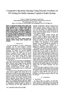
An arc fault occurs when a current path is established through the air via arcing due to a discontinuity in the current carrying conductors/junction or insulation breakdown in adjacent current carrying conductors. There are numerous interconnections present in a PV array as shown in Fig. 1. Due to continuous mechanical and thermal stresses, any of these interconnections may result in a sustained arc. A series arc fault occurs due to discontinuity in any of the current carrying conductors (CCCs) as a result of solder disjoint, cell damage, corrosion of connectors, damage caused by rodents, abrasion from different sources, etc. Parallel arc faults occur between two adjacent CCCs mostly due to insulation breakdown.
an AC generation system [5] [6]. The National Electrical Code® (NEC)-2011 requires a series arc-fault protection device, known as an arc-fault circuit interrupter (AFCI), installed in rooftop PV arrays with DC operating voltage equal to or higher than 80 V [5] [7]. There are several arc fault detection devices commercially available, and several other arc fault detection techniques have been proposed in literatures. Most of these methods are based on frequency spectrum analysis [8]- [12], and presence of an arc is confirmed if amplitude of a specific frequency or a band of frequencies increases beyond a certain threshold value. Arc fault detection using discrete wavelet transformation is presented in [13]. Example of several other methods proposed are use of direction of current flow at the onset of the arc fault [14], numerical analysis of the voltage and current of PV array [15] [16], etc. The proposed technique has the following advantages and limitations: (1) SSTDR can be used for both ground fault and arc fault detections, (2) this method can predict the
Regardless of the origins and types of the fault, an arc fault is harmful and potentially dangerous for a PV array since it may initiate a fire and spread in the surrounding areas especially in presence of flammable substances at close proximity of the PV array [1]-[4]. Since current through a DC arc does not possess a periodic zero crossing similar to an arc in AC systems, it is much more likely that an arc in a PV system will result in more sustained ignition compared to
978-1-4799-5776-7/14/$31.00 ©2014 IEEE
3294
Fig 1. Schematic diagram illustrating different interconnections in a PV array. (EGC= Equipment grounding conductor)
presence of a potential arc in the PV array, (3) this method does not require voltage and current information of the PV array, (4) can predict a potential arc in absence of or at very low solar irradiance, (5) the proposed technique requires a baseline data obtained from the PV array without arc fault to compare with the data obtained from the PV array under test. II.
SPREAD SPECTRUM TIME DOMAIN REFLECTOMETRY (SSTDR)
SSTDR is based on reflectometry, which is widely used for electrical characterization and fault detection in a transmission line. Simplified block diagrams of SSTDR device and a transmission line is shown in Fig. 2. When the length of the transmission line is longer than 1/10 times of the wavelength of the incident signal [17], reflection at the impedance discontinuities need to be considered. Reflection coefficient (ρ) is the ratio of the incident voltage signal to the reflected voltage signal at the load terminal as shown in equation (1), and it defines the strength of the reflected signal. Here, V+ and V- are incident and reflected voltage signals; Z0 and ZL are characteristic and load impedances correspondingly. SSTDR performs autocorrelation of the incident signal with the reflected signal to detect the presence and location of faults. Basic operations and dependence of ρ on the load impedance have been described in [19]. ρ=
VV
+
=
Z L - Z0 Z L + Z0
cables since there are wide variation in characteristic impedances along the length of the signal propagation in a PV array. In addition, the arc resistance changes during the evolution of arc, and therefore, it is expected that the reflected signal at arc terminal will change over short duration of time which is unlikely during a ground fault. As a result, it is possible to distinguish the presence of an arc fault from a ground fault by scanning the PV array over time and analyzing the pattern of the autocorrelation plots generated by the SSTDR hardware. An arc is a non-linear phenomenon in terms of its voltage and current relationship [13], and it generates noise in a wide band which is captured by the SSTDR’s signal receiver terminal as well. Therefore, it is expected that the received signal will contain not only the reflected signal but also the noise generated by the arc. The incident signal of SSTDR is pseudo random binary noise (PN code) modulated sine wave as shown in Fig. 3(a). In general, PN code possesses a frequency spectrum similar to a sinc function, and the width of the main lobe is twice the
(1)
Any variation in reflection coefficient or in the reflected signal is more important in case of fault detection in complex networks such as a PV array. However, these parameters may not be significant in case of a simple coax or power
(a)
(b) (a)
(c) Fig. 3. (a) carrier signal and incident signal generated by SSTDR hardware [18], (b) frequency spectrum of a pseudo random binary noise (PN code) with chip generation frequency equal to 24 MHz, (c) frequency spectrum of the SSTDR generated incident signal with center frequency equal to 24 MHz.
(b) Fig. 2. (a) Simplified block diagram of SSTDR hardware, (b) simple transmission line model [18] [19].
3295
inverse of the length of each chip (1 or 0) in time domain. Although it is possible to construct the incident signal with unequal chip length and time period of the carrier signal, a carrier time period equal to the chip length is mostly used in SSTDR implementations [18]. Frequency spectrum of PN code and incident signal of SSTDR is shown in Fig. 3(b)-(c), and it should be noted that the width of the main lobe is twice the frequency of the carrier sine wave. The reliable frequency range for detection of arc in PV lies within the range of 10kHz to 50 kHz [12], and it requires high sampling frequency to capture the frequency content that need to cover a range starting from 10 kHz to 48 MHz or higher for a carrier frequency of 24 MHz for performing discrete Fourier transformation. Therefore, time domain analysis is preferred.
(a)
III. ARC FAULT DETECTION: INTERMITTENT SCAN The WILMA LWG40414 board (based on SSTDR technology from Livewire Innovation [20]) has been used, and the positive and negative CCCs of the PV array were connected to the SSTDR hardware. The center frequency was always fixed at 24 MHz considering the length of the PV string and distance resolution. There are two major modes of operation in the SSTDR workbench: static and intermittent. The static mode requires external triggering for initializing each scan, and intermittent scan mode continuously scans the PV array once it is started. The scan speed during intermittent scanning may vary depending on the setup, and it was ~1200 scan/second during this experiment. This means about 1200 autocorrelation plots has been generated per second for the PV array under test.
(b) Fig. 4. Photograph of the facilities used at DETL at Sandia National Laboratories to perform the arc fault detection tests [19]
Experiments were performed at the Distributed Energy Technologies Laboratory (DETL) of Sandia National Laboratories (SNL) shown in Fig. 4, and a photograph of the arc generator used in this experiment is shown in Fig. 5. Schematics of the experimental setups for series and parallel arcs are shown in Fig. 6. Tests were performed using intermittent test mode to detect the presence of any arc. Each string consists of seven series connected PV modules, and specification of each module can be found in [19]. In case of series arc generation, two parallel strings were used as shown in Fig. 6(a), and the inverter was ON during the series arc generation only since the inverter may shut down during parallel arc generation due to low voltage at the terminals. The arc generator has been installed at position 1_0 during series arc tests and the autocorrelation plots generated by the SSTDR hardware are shown in Fig. 7. It is possible to detect the presence of an arc fault by observing the noise at the autocorrelation plots. More efficient fault detection algorithm can be developed by calculating area under autocorrelation difference plots using the static operation of the SSTDR hardwire which is discussed in next section. Autocorrelation plots generated by the SSTDR hardware during parallel arc fault by connecting the arc generator between location 1_0 and 5_4 are shown in Fig. 8. Data were captured for parallel arc faults at different locations of the
Fig. 5. Photograph of the arc generator.
PV string e.g., between 8_7, 7_6 etc. and 1_0, and similar results have been obtained. It is clear from the plots that any arc (series or parallel) adds significant noise in the autocorrelation plots. It should be noted that whenever a series arc is detected in the system, the inverter is required to be turned OFF to extinguish the arc. However, any parallel arc fault may sustain even after the inverter is turned OFF, and SSTDR can detect the presence of this parallel arc without any baseline subtraction.
3296
IV.
autocorrelation difference plot is higher than a predefined threshold obtained from the baseline data. Any open circuit introduced in series connected PV modules will result in higher reflection at the point of discontinuity, and it will result in higher oscillation of the signal generated by the SSTDR hardwire. Therefore, the area under the absolute autocorrelation plot increases if there is any open or short circuit introduced in a healthy PV string. Step by step procedures for generating absolute autocorrelation difference plot for open fault detection are depicted in Fig. 10.
OPEN FAULT DETECTION
Open fault detection of PV array can be performed during night or at low irradiance when the inverter is OFF, and the SSTDR hardware needs to work in static mode. SSTDR is based on the concept of reflectometry, and any open fault in a PV string results in the change of reflection coefficient at the location of open fault. Schematic diagram of the experimental setup is shown in Fig. 9. A baseline autocorrelation value is obtained from a healthy (without open fault) PV array, and it is compared with test data derived from the PV array under test condition to detect impedance variation.
Fig. 10(a) shows the autocorrelation plots for both healthy and PV string with fault at different locations, and Fig. 10(b) shows the difference between the autocorrelation
An arc fault is confirmed if the area under the absolute
(a)
(b) Fig. 6. (a) Schematic diagram of the set-up used for series arc fault detection, (b) schematic diagram of the set-up used for parallel arc fault detection.
Fig. 7. Presence of noise in autocorrelation plots during series arc faults.
Fig. 8. Presence of noise in autocorrelation plots during parallel arc faults.
Fig. 9. Schematic diagram of experimental setup for analyzing the impact of fault resistance during series arc fault.
3297
plots for the PV string without any fault and with open faults at various locations. It is clear that an open fault can be easily detected for locations 1_0, 4_3, and 8_7 by considering the autocorrelation difference only. However, fault at several locations e.g., 2_1, 3_2 etc., will remain undetected. In order to develop a robust algorithm to detect all open faults, absolute value of the autocorrelation difference plots are considered as shown in Fig. 10(c), and area under the absolute autocorrelation difference can detect the presence of open fault at all the locations in the PV string as shown in the bar plot in Fig. 10(d). Portion of the Fig. 10(d) is zoomed in Fig. 10(e) in order to clarify the robustness of the system. Therefore, SSTDR can be used for detection of open fault at different locations with the proposed algorithm, and this method does not require measurement of current or voltage of the array.
V. IMPACT OF FAULT RESISTANCE SSTDR can be used for detection of any increase in series resistance in a PV array. In order to demonstrate this phenomenon, a series resistance was inserted at various locations of a PV string as shown in Fig. 9. Three different resistors were tested: 0.5 Ω, 5 Ω, and 10 Ω. In all these cases, SSTDR can detect the increased resistance by calculating the area under the absolute autocorrelation difference plot described in previous section, and results are listed in Table I. Similar tests were repeated with two parallel strings as shown in Fig. 11. A parallel arc fault creates a low resistance path between two CCCs and this has been emulated using 0.5 Ω, 5 Ω, and 10 Ω resistors as depicted in Fig. 12. Any considerable increase in resistance in an existing current path
(b)
(a)
(c)
(d)
(e) Fig. 10. (a) Autocorrelation plot with no fault along with open fault cases in different locations with reference to Fig. 9, (b) difference between the autocorrelation baseline with no fault and open circuit fault cases at various locations, (c) absolute values of autocorrelation difference values shown in (b), (d) area under absolute autocorrelation difference plot at different fault locations, (e) zoomed view of (d) showing that the area under absolute autocorrelation difference plot for open fault at any location is higher than the area for a healthy PV string.
3298
Fig. 11. Schematic diagram of experimental setup for analyzing the impact of fault resistance in series arc fault with two parallel strings.
Fig. 12. Schematic diagram of experimental setup for analyzing impact of fault resistance in parallel arc fault. TABLE I. AREA UNDER ABSOLUTE AUTOCORRELATION DIFFERENCE PLOT FOR DIFFERENT FAULT RESISTANCES Fault type => Fault resistance => Fault location No fault 1_0 2_1 3_2 4_3 5_4 6_5 7_6 8_7
series arc fault and single string 10 Ω
5Ω
0.0683e5 3.9229e5 0.1630e5 0.1860e5 4.7518e5 0.4803e5 0.6422e5 0.6819e5 8.2669e5
0.0683e5 4.4934e5 0.0876e5 0.1037e5 5.2049e5 0.4721e5 0.5228e5 0.6111e5 8.5630e5
0.5 Ω
0.0683e5 3.9317e5 0.0832e5 0.0954e5 4.6740e5 0.4921e5 0.5803e5 0.9190e5 6.7807e5
series arc fault and two parallel strings 10 Ω
5Ω
0.1285e5 3.8888e5 0.5166e5 0.8892e5 4.7588e5 0.9718e5 1.1255e5 1.6036e5 4.3901e5
0.1285e5 3.5189e5 0.5437e5 0.8818e5 4.4690e5 0.9578e5 1.4973e5 1.4973e5 4.4934e5
or decrease in insulating resistance between two CCCs implies an indication of connection deterioration and can be considered as a sign of future arc. The proposed algorithm can confidently detect the presence of such increased resistances (Table I). Therefore, SSTDR can be used for early site inspection before any hazardous event occurs. VI. CONCLUSIONS A PV arc fault prediction and detection technique has been introduced in this paper. The proposed techniques can be applied for detection of both ground and arc faults and it does not depend on the solar irradiance or measurement of DC voltage and current of the PV array. Experiments were performed using different arc fault resistances and at different fault locations. The proposed technique can
0.5 Ω
0.1285e5 2.4739e5 0.7469e5 0.8727e5 3.7420e5 1.0252e5 1.2823e5 1.4692e5 3.8721e5
Parallel arc fault Fault resistance => Fault location No fault 1 2 3 4 5 6 7
10 Ω
22 Ω
0.1334e5 1.0042e5 0.9913e5 1.0197e5 2.3199e5 1.0564e5 1.2898e5 2.0199e5
0.1334e5 1.0482e5 0.9813e5 1.0569e5 2.3316e5 0.9974e5 1.2797e5 1.9093e5
confidently detect the presence of fault resistance irrespective of the value of fault resistances and fault locations inside the array. Detail analysis of all the test cases along with the potentials and limitations of the proposed arc fault prediction and detections technique has been described. VII. ACKNOWLEDGEMENT The authors express their appreciation to the US Department of Energy Office of Energy Efficiency and Renewable Energy for supporting this work. REFERENCES [1]
3299
J. Johnson, M. Montoya, S. McCalmont, G. Katzir, F. Fuks, J. Earle, A. Fresquez, S. Gonzalez, and J. Granata, “Differentiating series and
[2]
[3]
[4]
[5]
[6]
[7] [8]
[9]
[10]
[11]
[12]
[13]
[14]
[15]
[16]
[17]
[18]
parallel photovoltaic arc-faults,”38th IEEE PVSC, Austin, TX, 4 June, 2012. Johnson, J.; Oberhauser, C.; Montoya, M.; Fresquez, A.; Gonzalez, S.; Patel, A., "Crosstalk nuisance trip testing of photovoltaic DC arcfault detectors," Photovoltaic Specialists Conference (PVSC), 2012 38th IEEE , vol., no., pp.001383,001387, 3-8 June 2012. J. Strauch, M.A. Quintana, J. Granata, W. Bower, S. Kuszmaul, “Solar module arc fault modeling at Sandia National Laboratories,” 2011 NREL Module Reliability Workshop. Hastings, J.K.; Juds, M.A.; Luebke, C.J.; Pahl, B., "A study of ignition time for materials exposed to DC arcing in PV systems," Photovoltaic Specialists Conference (PVSC), 2011 37th IEEE , vol., no., pp.003724,003729, 19-24 June 2011. Jack D. Flicker& Jay Johnson, “Electrical Simulations of Series and Parallel PV Arc-Faults”, Photovoltaic Specialists Conference (PVSC), 2013 39th IEEE. Gab-Su Seo; Hyunsu Bae; Bo-Hyung Cho; Kyu-Chan Lee, "Arc protection scheme for DC distribution systems with photovoltaic generation," Renewable Energy Research and Applications (ICRERA), 2012 International Conference on , vol., no., pp.1,5, 1114 Nov. 2012. NFPA70, "Article 690 - Solar Photovoltaic Systems of National Electrical Code," ed. 2011. Jay Johnson, Scott Kuszmaul, Ward Bower, and David Schoenwald, “Using PV module and line frequency response data to create robust arc fault”, 26th EU PVSEC, Hamburg, Germany, 2011. Johnson, J.; Kang, J. "Arc-fault detector algorithm evaluation method utilizing prerecorded arcing signatures", Photovoltaic Specialists Conference (PVSC), 2012 38th IEEE, On page(s): 001378 – 001382. Dini, D.A.; Brazis, P.W.; Kai-Hsiang Yen, "Development of ArcFault Circuit-Interrupter requirements for Photovoltaic systems," Photovoltaic Specialists Conference (PVSC), 2011 37th IEEE , vol., no., pp.001790,001794, 19-24 June 2011. Shea, John J.; Luebke, Charles J.; Parker, Kevin L., "RF current produced from DC electrical arcing," Electrical Contacts (ICEC 2012), 26th International Conference on , vol., no., pp.1,6, 14-17 May 2012.R. Ammerman, T. Gammon, P. Sen, and J. Nelson, “DC-arc models and incident-energy calculations,” IEEE Trans. Ind. Appl.,vol. 46, no. 5, pp: 1810-1819, 2010. Texas instruments, “AN-2154 RD-195 DC Arc Detection Evaluation Board”, Application report, SNOA564F–June 2011–Revised December 2012. Online [http://www.ti.com/lit/ug/snoa564f/snoa564f.pdf]. Yao, X.; Herrera, L.; Ji, S.; Zou, K.; Wang, J., "Characteristic Study and Time Domain - Discrete Wavelet Transform Based Hybrid Detection of Series DC Arc Faults," Power Electronics, IEEE Transactions on , vol.PP, no.99, pp.1,1, 0. Strobl, C.; Meckler, P., "Arc Faults in Photovoltaic Systems," Electrical Contacts (HOLM), 2010 Proceedings of the 56th IEEE Holm Conference on , vol., no., pp.1,7, 4-7 Oct. 2010. Schimpf, F.; Norum, L.E., "Recognition of electric arcing in the DCwiring of photovoltaic systems," Telecommunications Energy Conference, 2009. INTELEC 2009. 31st International , vol., no., pp.1,6, 18-22 Oct. 2009. Buddha, S.; Braun, H.; Krishnan, V.; Tepedelenlioglu, C.; Spanias, A.; Yeider, T.; Takehara, T., "Signal processing for photovoltaic applications," Emerging Signal Processing Applications (ESPA), 2012 IEEE International Conference on , vol., no., pp.115,118, 12-14 Jan. 2012. Alam, M.K.; Khan, F.H.; Johnson, J.; Flicker, J., "PV faults: Overview, modeling, prevention and detection techniques," Control and Modeling for Power Electronics (COMPEL), 2013 IEEE 14th Workshop on , vol., no., pp.1,7, 23-26 June 2013. P. Smith, C. Furse, J. Gunther “Analysis of spread spectrum time domain reflectometry for wire fault location”, IEEE Sensors Journal, Vol. 5, Issue 6, December 2005, pp 1469 -1478.
[19] Alam, M.K.; Khan, F.; Johnson, J.; Flicker, J., "PV ground-fault detection using spread spectrum time domain reflectometry (SSTDR)," Energy Conversion Congress and Exposition (ECCE), 2013 IEEE , vol., no., pp.1015,102, 15-19 Sept. 2013. [20] Livewire Innovation (http://livewireinnovation.com).
3300