2009 IEEE International Advance Computing Conference (IACC 2009) Patiala, India, 6-7 March 2009
Spread Spectrum Image Watermarking with Digital Design Sudip Ghosh, Pranab Ray
Santi P Maity, Hafizur Rahaman
School of VLSI Technology Bengal Engineering And Science University, Shibpur Howrah, India sudip_etc @ yahoo.co.in, ronmarine 14 @ yahoo.co.in
Department of Information Technology Bengal Engineering And Science University, Shibpur Howrah, India
[email protected], rahaman_h @ yahoo.co.in
used to design fragile and semi-fragile watermarking by keeping the chip rate smaller. The term chip rate in SS watermarking indicates the number of cover signal's sample over which each watermark bit is spread [7]. Such image
Abstract-In recent time watermarking technique becomes a potential solution for copyright protection, authentication and integrity verification of digital media. Among the widely used
watermarking techniques, spread spectrum modulation based method becomes appealing due to its inherent advantage of greater robustness and is used widely for various applications. Some watermarking applications, for example, digital television broadcasting, internet protocol television (IP-TV), etc. essentially demand development of low cost watermark algorithms in order to implement in real-time environment. This paper proposes a block based multiple bit spatial domain spread spectrum image watermarking scheme where a gray scale watermark image is represented by less number of binary digits using novel channel coding and spatial biphase modulation principle. VLSI implementation using Field Programmable Gate Array (FPGA) has been developed for the algorithm and circuit can be integrated into the existing digital still camera framework. The proposed image watermarking algorithm may be applied for authentication as well as secured communication in real time environment.
watrmrking alithms wen de
i
nsatial domai
marovide falityof reale implementation tough hardware realization. Hardware implementation of digital
watermarking offers advantages over software realization in terms of less area, low execution time, and less power [8],[9]. If a chip is fitted in the digital devices, the output video or images can be marked right at the origin although the same can be done using software after those videos or images downloaded to the computer. But in this case embedding software will take more time compared to hardware. The example of TV broadcast will highlight the significance where . . digital media is to be marked in real time and hardware is the only solution. VLSI architecture have been developed for some of the digital image and video watermarking algorithms.
The objective of this paper is to develop an image watermarking algorithm that can serve the purpose of media authentication as well as secured communication of a image like message signal in real time environment. This has been accomplished by exploiting the strong spatial correlation of I. INTRODUCTION the neighboring pixel values of of the the cover image. This c eiono fesrltv relatiessaiiyo mSB (mos Although it is easy to process, store and transmit almost noise h S ms free digital multimedia signals through general purpose significant bit) planes of the gray levels against various image mlieisgnsthou ital di channel w franee dig h modern gecne purose processing operations and is used for watermark signal have to keep in mind about the emerging problems like representation. Gray scale image is used as information copyright protection, ownership identification, authenticity, signal/watermark so that decoded message preserves its integrity verification and security of the digital data recognizability when watermarked images undergo noise transmission. Digital watermarking has proven to be an addition or other signal processing operations. Robustness is efficient solution over the years to these problems [1]. A lot further improved using channel coding scheme in the form of of effort has been dedicated to the development of robust variable redundancy that is incorporated among the different watermarking schemes to achieve these goals [2],[3]. Another bit planes of the watermark based on their relative possible, but less investigated, application of digital significance. Spatial bi-phase modulation scheme reduces watermarking is for the authentication of multimedia content effective payload capacity that is increased in channel coding and to detect the degree of malicious tampering of media scheme. VLSI design using FPGA has also been developed content [4]. The importance of digital content authentication for both watermark embedding and decoding process. has mde thdeveopmen of fagileand smi-frgile The rest of the paper iS organized as follows. Section II watermrking cheme hot rsearchtopic.describes the proposed watermarking algorithm. Section III Spread spectrum (SS) watermarking, although has proven to.. rpesnstedgtldsg fpooe ehdrsetvl be cryptographically secured and robust [5],[6] may also be
Keywords- SS watermarking, channel coding, biphase modulation, FPGA, VLSI
corlto.
978-1-4244- 1888-6/08/f$25.00 Q 2008 IEEE
868
using FPGA. Section IV presents results and conclusion is made in section V. II. PROPOSED WATERMARKING ALGORITHM The following two subsections describe different steps in watermark embedding and decoding process respectively. First the gray scale image like watermark information is converted to equivalent binary watermark and is then embedded directly to the pixel values of each block using SS modulation. During decoding, watermark information is extracted using correlator and the extracted binary watermark is then converted to the grayscale image using channel decoding and spatial bipahse demodulation. A. Message encoding and watermark embedding Step 1: Binary messageformation The cover image ( I ) is divided into ki x ki non overlapping blocks where the value of ki may be 2, 4, 8, 16 etc. The MSB plane of 2-D pixel values of each block are converted to 1-D string and are concatenated to form a large string of pixel values (string 1). Another binary string is formed using the different bit plane values of the gray-scale watermark image. An extended binary string (string 2) is made by incorporating different degree of redundancy (repeating by suitable odd number of times) among the various bits based on their relative significance. Strings 1 and 2 are partitioned into sub strings of equal and fixed number of symbols. If there occurs more than 50% positional match of the symbols in the two respective sub strings of strings 1 and 2, a bit '1' is assigned for the sub string otherwise bit '0'. Bit '1' indicates in-phase condition of two sub strings while out of phase condition is denoted by bit '0'. Assigning a binary digit corresponding to each substring of particular number of symbols is called as biphase modulation technique. The newly obtained binary string is the derived watermark to be embedded in the host signal. Step 2: Watermark embedding & formation of watermarked image It is preferable to use antipodal signaling scheme for data embedding in order to increase robustness performance. So the data embedding rule can be expressed as follows: Xe =X + kP if b = 0 X - kP if b = I
Where X is the pixel value of the cover image, Xe is the pixel ' value of the watermarked image, k is the modulation index, P nie matrix. arx iS the PN(Pseudo noise) B. Watermark dehiding & message decoding The watermark recovery process requires the sets of PN mates (Pi that wereduse fr datarebeddig Differen
is~~~~ th'NPed ~
Correl Sr*tep cutontthe Correlation values between
watermarked image matrix and each code pattern of the set (Pi) are calculated. We have a total of (Mm.Nm) (equal to the number of watermark bits) correlation values (qul) where i=1, 2,.. Mm.Nm. The decision rule for the decoded watermark bit iS as follows:
(i) for [ui > 0, the extracted bit is 0 (ii) for [ui < 0, the extracted bit is 1. Step 2: Substring decoding MSB plane of the watermarked image or its distorted version is picked up in the same way as was used for binary message formation and partitioned into substrings of fixed and equal number of bits. Biphase demodulation scheme is used in this stage. Based on the value of a binary digit in the decoded watermark, the substring either remains unchanged (if detected bit is '1') or complemented (if detected bit is '0').
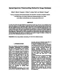
Step 3: Message decoding Each substring obtained is then partitioned into sub substrings (smaller substrings) according to the rules used during watermark embedding. Binary detection is then applied for each sub substring based on the majority decision rule i.e. if more than 50% symbols are '1' in a sub substring, decision for decoding is '1', otherwise '0'. The binary digit of all the sub substrings of a substring are then converted to the pixel and gray scale watermark image is decoded. III. DIGITAL DESIGN OF PROPOSED METHOD The synthesis of both the watermark embedding and decoding have been implemented on Xilinx (ISE version 8.2i) based FPGA.We have chosen Virtex series of FPGA to fit the complexities of the design. The device used is xc4vlx2510ff676 for the implementation and the language used is VHDL.The behavioral simulation was done with Modelsim XE III 6.le to verify the functionality of the design and is shown in Fig. 1. A testbench was also written in VHDL to give the input vectors for the simulated program. Fig. 2 shows the top-level RTL schematic.
The VLSI design consists of two parts: A. Digital Design of Watermark embedding. B. Digital Design of Watermark decoding. A. Digital Design of Watermark embedding
The VLSI design is made here for the cover image of size (256 x 256) with 8 bits per pixel. On the other hand, the image size taken per ~~~~watermark pixel.aow the cove iage was is p(64 t x 64), xi with 4 bits 8) nonpixel. Now, the cover image is partitioned in (8 x 8) nonoverlapping blocks and watermark image in (2 x 2) nonblocks. Say the partitioned watermark images are overlapping d as shown of the cover and a, b, c, Fig.2. The the watermark imageinfollowed the conversion of the by partitioning integer
image data to binary was done with the help of MATLAB. With the binary image data for both the partitioned cover and the watermark put them in the The partitioned bench as input cover andimage, input wewatermark image. test pattoe coe an th waemr img aainbnr r paddwt0inhesgbttorrsntheindime So 8 bi/ie gre scl oe mg i o dt.'
by 9
bits
and 4
bits/pixel
greyscale watermark
2009 IEEE Internxationxal Advanxce Computing Conference (IACC 2009)
ersne
image iS 869
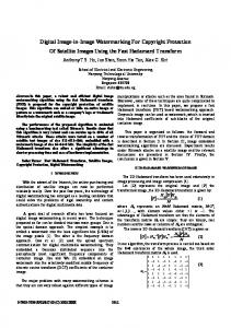
represented by 5 bits. Then normalization is done for the pixel values of the cover image by subtracting 128 from each gray values and normalization circuit is shown in Fig. 3. Figs. 4,5,6 represent the corresponding redundancy addition to the respective bit plane of each pixel value for the watermark image. Fig. 7 finally indicates how a string of 64 bits are formed for the 4 pixel values of the watermark image. The generation of Pseudo Noise(PN) code using LFSR( Linear Feedback Shift Register) is shown in Fig.8. Fig. 9 shows the required circuit for watermark embedding. i
219.542MHz). Maximum output required time after clock is 102.195ns. Maximum combinational path delay: 103.346ns.
+
a B. Digital Design of Watermark Decoding
-
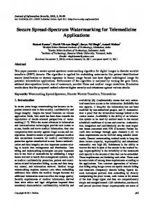
Watermark decoding is accomplished by calculating the correlation values between the watermarked image block and /testy_vhd/d3 respective LFSR output matrices. The detailed circuit for correlation calculation is shown in Fig. 10, yxl shown in the figure represents the LFSR output matrix coefficients. Similarly block Embedx buffer represents elements ofd+ II +6.1e!I embedded matrix Blocks A, B and C shown in this figure + represent the hardware for necessary multiplication and + addition for correlation calculation. Block F indicates the accumulated sum for the correlation values and its output is divided by 64 (shown in G) to obtain normalized correlation value.n reprte
.
1
_.
Ps
IV RESULTS
A.
Performance evaluation
The proposed watermarking methodology is based on the combination of channel coding and spread spectrum technique. We consider a 4 bits/pixel of size ( 64 x 64) and i 256 x 256) grayscale images as 8bits/pixel of size watermark and the cover image respectively for experiment purpose. The binary watermark image of size (32x 32) is obtained using spatial bi-phase modulation by assigning a binary digit for a substring consisting of 64 symbols. Figs. 11 (a)-(e) show the test image, message signal, binaryTh intermediate watermark, watermarked image, and decoded message signal respectively. Figs. 11(b) and I (e) show that the decoded message is not identical to that of message signal du oencoding loss. The proposed SS watermarking method has been tested against mean, median filtering, noise addition, image sharpening and lossy compression operations and the experiment results show that the proposed method is robust against such signal processing operations. However, results are not reported here due to space limitation. Detection reliability of multiple bit embedding in each block indicates relative modification/tampering occurred in the respective block. B.
Results of Hardware Implementation
Fig. 1: Behavioral Simulation output shown in Modelsim XE 111k6. le
Watelmulak
rig.4) b(0;4)
elR 3) comparpL
(O4)E
msbl(0:3)
Watemk
isbl(0;3)
Deoig
msb1(O;.3)
m
.DatainAlX3O;) C pDani
C3Xfrn)
dl d2
d4e
Dahainx63M0;8) ~1O
N10
Clk
Watemairk Deiecoiio
Deoi
Comladon aluah
Read Enab E
Datainx
Write enable Read Enable
P
Fig. 8:
Normalization Circuit
Fig. 3:
LFSF
PN Code Generator using LFSR
Table 1: Synthesis Results from Xilinx ISE 8.2i Datain
(0)(0 8)
Covei
(0)10 8)
Normalizatior
Imagr Datain
lmage ImagE
t(o3)
Additio bx(0 15) 1R nI
c(O3)
R
)
(03)
PN Code
3
Logic Used Utilization
Available
Number
10752
of
11536
Utilization 107%
S ices \
1 1
1
N
15)arE
;gi; i
x
4
T
X(O15 cx(O 15)
s)
PN Code
Generator Generator Generator Generator
(68) ax(0 15)
X
PN Code
Datanormalizec|
(63)08)
Watermark
PN Code
Datanormalizec
-
-_;CLK
Coun
E
Compa)3i
Number of Slice Flip-
296
21504
1%
Number of 4 input LUTs
21692
21504
100%
Number of bonded IOBs
649
448
144%
Number of
2
32
6%
S.
l
Flops
se
CLS K
1
*
K
__
2
__
3
K
__
*
SUR
4
__
*
SUR
SUR
K
*
~~~~GCLKs
SUR
(b) +1.
+1.
+/1=
+/ ,1 Embec (06 QB
QB
ax(4)
ax(3) Q
_D
> QBE
ax(5) -D
Q
ax(6) Q
>QB
QB
Q
D
> QB
ax(7) D
I_
Q
>QBE
ax(8) Q
D
QB
LK
Fig.4: Encoding of MSB(Most significant bit) of Watermark pixel.(Adding redundancy 9 times)
Lod
n(2)
EL I
~
~
I
E
LE
I
CLK
Fig.5: Encoding of the 2nd bit of Watermark pixel. (Adding redundancy 5 times)
Load a(3)
\
Load D
ax(14)
Q
a(4)
QB
CLK~~~~~~~L Fig. 6: Encoding of 3rd and 4th bit of watermark pixel.( Without adding redundancy)
ax(O... 15)
,1 1
hx(O... 15)
1
dx(O... 15)
cx(O... 15)
dl
1
I5
Ystring Register (64 bit) Fig. 7: Encoding of4 bits watermark image into 64 bits
872
2009 IEEE Internxationxal Advanxce Computing Conference (IACC 2009)
lC enable
Start add
clk E
Embedx
Buffer
A
O~~~~~~~N-
G
~~~~~~~~~~~~~~~~~~~~~~~~Divider 64
corre
Multiplexer
p ~~~~~~~ac
ck
Fig 10 Correlation calculation
V. CONCLUSION
The paper proposes a semi-fragile spatial image watermarking scheme by combined use of channel coding and spread spectrum modulation. The algorithm is simple with low computation cost and can be easily implemented in hardware. Digital design of the proposed algorithm using FPGA is also developed and thus makes it suitable for real time authentication as well as secured communication. Current work is going on to develop the dedicated digital system using FPGA chip.
[9]
IEEE Transaction on Signal Processing, vol. 51, pp. 925- 938, April 2003. S. P. Maity, A. Banerjee, A. and M. K. Kundu, VLSI design of Spread Spctu 1th NainlCnfrne National Conference oon Spectrum Img Image Waemakn Watermarking-13t
communications (NCC-2007), Indian Institute of Technology, Kanpur,
India, January 26-28, 2007, pp. 251-257.
REFERENCES [1]
[2]
[3] [4] [5]
[6] [7] [8]
M. Wu and B. Liu, Multimedia Data Hiding, New York: SpringerVerlag, 2002. Special issue on copyright and privacy protection, IEEE Journal on Selected Areas in Communication (JSCA), 16(4), May 1998. Special issue on enabling security technologies for digital right management, Proceedings of IEEE, 92(6), June 2004. A. H. Paquet, R. K. Ward, and I. Pitas, Wavelet packet-based digital watermarking for image verification and authentication, Signal processing, 83, pp. 2117-2132, 2003. I. J. Cox, J. Kilian, T. Leighton, and T. Shamoon, Secure spread spectrum watermarking for multimedia, IEEE Transaction on Image Processing, 6 (12), pp. 1673-1687, 1997. S. P. Maity, M. K. Kundu and T. S. Das, "Robust SS Watermarking with improved capacity", Pattern Recognition Letters "Advances in Visual Information Processing", Elsevier, 28, pp. 350-357, 2007. 5. P. Maity and M. K. Kundu, "A blind CDMA image watermarking scheme in wavelet domain," Proc. Of IEEE Int. Conf: on Image Proc., Singapore, pp. 2633-2636, 2004. N. J. Mathai, D. Kundur, and A. Sheikholeslami, Hardware implementation perspectives of digital video watermarking algorithms,
2009 IEEE Internlationlal Advance Computing Conference (IACC 2009)
873