Quasi-direct writing of diffractive structures with a focused ion beam Yongqi Fu Innovation in Manufacturing Systems and Technology, Singapore—Massachusetts Institute of Technology Alliance, 50 Nanyang Avenue, Singapore 639798
[email protected]
Ngoi Kok Ann Bryan and Wei Zhou Precision Engineering and Nanotechnology Center, School of Mechanical and Production Engineering, Nanyang Technological University, 50 Nanyang Avenue, Singapore 639798 http://www.ntu.edu.sg/home/yqfu/fyqpage.htm
Abstract: A new method for fabrication of diffractive structures, which we call quasi-direct writing, is illustrated. The diffractive structures can be generated by changing the pixel spacing along the direction of the cross scan (with zero overlap) and keeping the pixel spacing constant along the other scan direction, with a normal overlap of 50%–60%, while the substrate surface is scanned with a focused ion beam (FIB). Quasi-direct writing is a method for achieving special customer designs when the milling machine has no computer programming function. Diffractive structures with various periods and depths can be derived by controlling the parameters of pixel spacing, beam current, ion incidence angle, and the scan time or ion dose. The method is not restricted to any one material and can be used for metals, insulators, and semiconductors. 2004 Optical Society of America OCIS codes: (220.0220) optical design and fabrication, (050.1970) diffractive optics, (050.1970) microstructure fabrication.
References 1. 2. 3. 4.
5. 6.
Andrei Y. Smuk and Nabil M. Lawandy, “Direct laser writing diffractive optics in glass,” Opt. Lett. 22, 1030 (1997). Michael T.Gale, Markus Rossi, Jorn Pedersen, and Helmut Schutz, “Fabrication of continuous-relief microoptical elements by direct laser writing in photoresists,” Opt. Eng. 33, 3556 (1994). T. Fujita, H. Nishihara, and J. Koyama, “Fabrication of microlenses using electron-beam lithography,” Opt. Lett. 6, 613 (1981). Fu Yong-Qi and Ngoi Kok Ann Bryan, “Diffractive optical elements with continuous relief fabricated by focused ion beam for monomode fiber coupling,” Opt. Express 7, 141-147 (2000). http://www.opticsexpress.org/abstract.cfm?URI=OPEX-7-3-141. Yongqi Fu and Ngoi Kok Ann Bryan, “Hybrid micro-diffractive-refractive optical element with continuous relief fabricated by focused ion beam for single-mode coupling,” Appl. Opt. 40, 5872 (2001). Yongqi Fu and Ngoi Kok Ann Bryan, “Self-organized formation of a blaze grating like structure on Si(100) induced by focused ion beam scanning,” Opt. Express 12, 227 (2004). http://www.opticsexpress.org/abstract.cfm?URI=OPEX-12-2-227
#4063 - $15.00 US
(C) 2004 OSA
Received 22 March 2004; revised 5 April 2004; accepted 13 April 2004
3 May 2004 / Vol. 12 No. 9 / OPTICS EXPRESS 1803
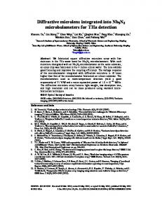
1. Introduction Currently there are three main direct writing methods for fabrication of micro-optical elements: laser direct writing [1,2] (LDW), electron-beam lithography [3] (EBL), and focused ion-beam direct milling [4,5] (FIBM). FIBM direct writing requires a programming function (called MDDL in the operation software for our machine, model Micrion 9500EX) that enables the users to write customer-designed programs; the programming function has special commands provided by the machine manufacturer to control the whole milling process to yield the desired structures. In this way the designed gratings can be directly milled point by point and line by line according to the computer program. (This process transfers the designed patterns by direct impingement of the ion beam on the substrate. Different points correspond to different milling depths of the designed continuous relief. The depth is derived from discrete data, which have been converted from the designed continuous-relief profile.) All the controlled design parameters (depth and lateral dimensions) are accounted for in this special program. However, not every model of the FIB machines has the MDDL programming function; e.g., the FEI Quanta series and Seiko series lack this function. It is difficult to fabricate diffractive structures by FIBM with FIB machines that lack the programming function. In this paper we introduce a method for which the programming function is not required. In other words, it is programming-function free. We call our method quasi-direct writing. Its principle is changing the pixel spacing of the direction along the cross scan (Y, represented by psy), as shown in Fig. 1 and keeping the pixel spacing of the other scan direction (the X direction, represented by psx) constant, and vice versa. (The normal overlap for the X direction is 50%–60%). Overlap in the cross-scan direction is zero. Gratings can be directly generated with different periods that correspond to the different Y pixel spacings. The method reported here also differs from our previously reported method of purely selforganized formation [6], in which the diffractive structure is spontaneously generated during sputtering erosion under ion bombardment, a self-organized formation caused purely by the competition between smoothing, driven by surface energy, and roughening, induced by the sputtering removal of material. The process of radiation-enhanced surface transport, resulting in surface smoothing in which relaxation by viscous flow (for amorphous materials) and surface diffusion (for crystal materials), plays a dominant role. But the purely self-organized formation strongly depends on the substrate material (it has strong material selectivity). We have only found two materials that exhibit this effect, TiNi thin film and Si (100) [6]. Quasidirect writing is a guided or pixel-spacing-controlled self-formation induced by changing the pixel spacing of the cross-scan direction. 2. Experimental setup The milling experiments were carried out by our FIB machine (a Micrion 9500EX dual-beam system), which is equipped with a liquid-gallium ion source and is integrated with a scanning electron microscope (SEM), an energy-dispersion x-ray spectrometer (EDX) facility, and gasassisted etching (GAE) functions. This machine uses a focused Ga+ beam with an energy ranging from 5 to 50 keV, a probe current from 4 pA to 19.7 nA, and a beam-limiting aperture size from 25 to 350 µm. For the smallest beam currents the beam can be focused to as small as 7 nm in diameter at full width at half-maximum (FWHM). The substrate material in our experiments is Si (111). The diffractive structures were characterized by an atomic force microscope (AFM), model Nanoscope (R) IIIa from Digital Instruments.
#4063 - $15.00 US
(C) 2004 OSA
Received 22 March 2004; revised 5 April 2004; accepted 13 April 2004
3 May 2004 / Vol. 12 No. 9 / OPTICS EXPRESS 1804
h psy
h
W psy
psx
W
h
X
psx Y (a)
(b)
Fig. 1. Schematic of FIB digital scanning steps and sizes in the defined scan area of L × W. Overlap (h) in both the X and the Y direction can be controlled by varying the X- and Y-direction pixel spacing. (a) Overlap of 50%–60% in both the X and the Y scan direction for FIB direct writing; (b) overlap of 50%–60% in the X direction and zero in the Y direction for quasi-direct writing.
3. Results and discussion Figures 1(a) and 1(b) are schematics of the FIB digital scanning steps for both direct writing and quasi-direct writing methods, respectively. Figure 2 is the beam current versus the period and depth of the fabricated diffractive structures. It can be seen that, for the same ion dose of 1.5 nC/µm2 and scan time of 19 min, the depth for a beam current of 2 nA is much smaller than for a current lower than 1 nA. For currents ranging from 1 nA to 99 pA, variations in depth are smaller. The period increases as the beam current increases. This may be the reason that the tail of the Gaussian beam distribution still has enough energy for material sputtering with the high beam current of 2 nA. The high current causes a strong redeposition effect during beam scanning, which greatly reduces the depth of the grooves. Gratings with a period 350
900
300 250 200 150
700
100
Depth (nm)
Period (nm)
800
50
600
0 0
500
1000
1500
2000
Beam current (pA) Fig. 2. Ion beam current versus lateral dimension and depth of the diffractive structures measured with an AFM in a 15 µm × 15 µm area. Scanning was carried out with an ion energy of 40 keV, an ion incidence angle of 0°, ion dose of 1.5 nC/µm2, and beam current of 569 pA. X and Y pixel spaces are 0.02 and 0.6 µm, respectively. The inset FIB images are for beam currents of 99 pA and 2 nA. The substrate material is Si (111).
#4063 - $15.00 US
(C) 2004 OSA
Received 22 March 2004; revised 5 April 2004; accepted 13 April 2004
3 May 2004 / Vol. 12 No. 9 / OPTICS EXPRESS 1805
of ~100 nm and a depth of ~50 nm can be fabricated with extremely small beam diameters (~20 nm) and low currents (~10 pA). Figure 3 shows the ion energy versus the period and depth of the diffractive structures. It can be seen that the depth and period increase as the ion energy increases. There are no ripples observed for the ion energy below 25 keV owing to the large aberration of the focusing system, which greatly reduces the focusing quality of the beam. The higher the ion energy, the better the focusing quality of the beam will be. A large spherical aberration still exists for an ion energy of 25 keV and causes the large difference in period and depth formed at this energy. The ion incidence angle is another factor in grating
800 290 790
Period (nm)
770 270 760 750
Depth (nm)
280
780
260
740 250 730 20
25
30
35
40
45
Ion enrgy(keV) (keV) Ion energy Fig. 3. Ion energy versus lateral dimension and depth of the diffractive structures measured with an AFM in a 15 µm × 15 µm area. Scanning was carried out with an ion incidence angle of 0° and beam current of 569 pA. X and Y pixel spaces are 0.02 and 0.8 µm, respectively. The ion dose is 1.5 nC/µm2. The substrate material is Si (111). The dotted line indicates that no ripples are observed for ion energies below 25 keV.
#4063 - $15.00 US
(C) 2004 OSA
Received 22 March 2004; revised 5 April 2004; accepted 13 April 2004
3 May 2004 / Vol. 12 No. 9 / OPTICS EXPRESS 1806
240 2100 200
160
1500 1200
120
900
80
600
40 0
20
40
o
60
Depth (nm)
Period (nm)
1800
80
Ionincidence incident angle Ion angle ((°)) Fig. 4. Ion incidence angles versus lateral dimension and depth of the diffractive structures measured with an AFM in a 15 µm × 15 µm area. The scanning was carried out with ion energy of 40 keV, a scan time of 64 min, and a beam current of 569 pA. X and Y pixel spaces are 0.02 and 0.6 µm, respectively. The inset AFM images are for ion incidence angles of 0° and 70°. The substrate material is Si (111).
400
2000
320
240 1000 160
Depth (nm)
Period (nm)
1500
500 80 0 0 0.0
0.5
1.0
1.5
Y pixel space (µm)
2.0
Fig. 5. Y pixel spaces versus lateral dimension and depth of the diffractive structures measured with an AFM in a 15 µm × 15 µm area. X pixel spaces were fixed at 0.02 µm. The scanning was carried out with an ion energy of 40 keV, an ion dose of 1.5 nC/µm2, ion incidence angles of 0° 45°, and 80°, and a beam current of 569 pA. The inset FIB images correspond to Y pixel spaces of 0.1 and 2 µm, indicated by the arrows. The white arrows in the FIB images show the projection direction of the ion beam and scan path. The substrate material is Si (111).
#4063 - $15.00 US
(C) 2004 OSA
Received 22 March 2004; revised 5 April 2004; accepted 13 April 2004
3 May 2004 / Vol. 12 No. 9 / OPTICS EXPRESS 1807
2
Ion dose (nC/µm ) 0
2
4
6
8
10 300
840 820
250 200
780 760
150
740 720
Dpeth (nm)
Period (nm)
800
100
700 680
50
660 0
10
20 30 40 50 Ion-beam scan time time (min) Ion beam scan (min.)
60
70
Fig. 6 Ion-beam scanning time versus lateral dimension and depth of the diffractive structures measured with an AFM in the scanned 15 µm × 15 µm area. The scanning was carried out with ion energy of 40 keV and beam current of 569 pA. X and Y pixel spaces are 0.02 and 0.6 µm, respectively. The inset AFM images correspond to scanning times of 4 and 64 min, indicated by the arrows. The diffractive structures changed from sinusoidal to blazelike topographies. The substrate material is Si (111).
(a)
(c)
(b)
(d)
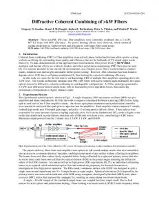
Fig. 7. Diffractive structure change for various process parameters with quasi-direct FIB writing on quartz, measured with an AFM. (a) Three-dimensional (3D) image of the grating with a line density of 787 lines/mm, milled with scan time 8 min, beam current 569 pA, and incidence angle 15°. (b) 2D profile with depth 24.4 nm and width 1270 nm. (c) 3D image of the grating with a line density of 900 lines/mm, milled with scan time 32 min, , beam current 569 pA, and incidence angle 60°. (d) 2D profile with depth 439 nm and width 1110 nm.
#4063 - $15.00 US
(C) 2004 OSA
Received 22 March 2004; revised 5 April 2004; accepted 13 April 2004
3 May 2004 / Vol. 12 No. 9 / OPTICS EXPRESS 1808
formation. It can be seen from Fig. 4 that the period increases and the depth degrades as the ion incidence angle α increases. The period is proportional to ∆/(cos α), where ∆ is the period at α = 0° (the ion beam is perpendicular to the substrate surface). The density of the beam energy decreases as the ion incidence angle increases; this causes degradation of the milling depth, which is as small as 43 nm at α = 80°. In addition, the sputtering yield first increases with α and then greatly decreases at α > 70°. At glancing angles, surface channeling plays an important role that causes the sputter yield to decrease, which is another reason for the smaller depths at large incidence angles. Figure 5 shows the Y pixel space, psy, versus the period and depth of the gratings. The X pixel space, psx, is fixed at 20 nm in this experiment. It can be seen that the period and depth increase approximately linearly with increases in the Y pixel space. For generation of high-density gratings, not only the Y pixel space but also the beam current should be small, because a smaller beam spot is necessary to yield fine lines with smaller widths in this case. To keep zero overlap in the direction of the cross scan to write the grating with a higher line density, psx, psy must satisfy the relationships psx/df ≤ 1.5 and psy/df ≥ 8, where df is the beam spot diameter. The depth and period are approximately proportional to the ion-beam scanning time and ion dose, as is shown in Fig. 6. The period increases fast as the scan time increases from 0.5 to 4 min. Then it increases slowly with the scan time and ion dose. An interesting effect was observed for milling carried out at an ion incidence angle of 0°: The diffractive structure changed from sinusoidal at the beginning to a sawtoothlike blaze grating at the end with a scanning time of 64 min; see the inset AFM images in Fig. 6. This phenomenon is related to the substrate material, with competition between ion-sputtering-induced surface roughening and smoothing caused by surface diffusion during the process. Therefore different materials may have a different transition condition; e.g., the scan time is longer than 4 min at an incidence angle of 0° for Si (111) and longer than 16 min at an incidence angle of ~30° for quartz, as is shown in Fig. 7. The method of quasi-direct writing is based on changing the pixel spacing, which is the key factor among these process parameters. Apart from Si (111) and quartz, we tried similar quasi-direct writing experiments with other materials, such as GaAs, glass BK7, InP, and GaN. Similar results were obtained. Therefore we draw the conclusion that quasi-direct writing has no material selectivity. 4. Summary In summary, the quasi-direct writing method has the advantages of requiring no programming function and not excluding any material. The substrate materials can be metals, insulators (e.g., BK7 glass or quartz), or semiconductors (e.g. Si, GaN, GaAs, or InP). It is essential for users with FIB machines that have no customer programming function. It also provides an additional flexible option for those people who want to use FIB machines to fabricate their diffractive structures. It is more suitable for locally writing the gratings used in distributed feedback laser diodes (DFB) and the Bragg gratings in distributed Bragg reflector (DBR) laser diodes. Any FIB machine can fabricate the gratings with this method. Diffractive structures with circular symmetry, such as Fresnel plates, also can be fabricated if the FIB machine scans with a circular path. Acknowledgments This research was supported in part by the Funding for Strategic Research Program on Ultraprecision Engineering of the Agency of Science, Technology and Research, Singapore, and by the Innovation in Manufacturing Systems and Technology Program in Singapore— Massachusetts Institute of Technology Alliance.
#4063 - $15.00 US
(C) 2004 OSA
Received 22 March 2004; revised 5 April 2004; accepted 13 April 2004
3 May 2004 / Vol. 12 No. 9 / OPTICS EXPRESS 1809