letters to nature
................................................................. Rapid prototyping of patterned functional nanostructures
Hongyou Fan³, Yunfeng Lu², Aaron Stump³, Scott T. Reed², Tom Baer², Randy Schunk², Victor Perez-Luna³, Gabriel P. LoÂpez³ & C. Jeffrey Brinker²³ ³ The University of New Mexico Center for Micro-Engineered Materials and Department of Chemical and Nuclear Engineering, Albuquerque, New Mexico 87131, USA ² Sandia National Laboratories, Albuquerque, New Mexico 87185, USA ..............................................................................................................................................
Living systems exhibit form and function on multiple length scales and at multiple locations. In order to mimic such natural structures, it is necessary to develop ef®cient strategies for assembling hierarchical materials. Conventional photolithography, although ubiquitous in the fabrication of microelectronics and microelectromechanical systems, is impractical for de®ning feature sizes below 0.1 micrometres and poorly suited to pattern chemical functionality. Recently, so-called `soft' lithographic approaches1 have been combined with surfactant2,3 and particulate4 templating procedures to create materials with multiple levels of structural order. But the materials thus formed have been limited primarily to oxides with no speci®c functionality, and the associated processing times have ranged from hours to days. Here, using a self-assembling `ink', we combine silica± surfactant self-assembly with three rapid printing proceduresÐ pen lithography, ink-jet printing, and dip-coating of patterned self-assembled monolayersÐto form functional, hierarchically organized structures in seconds. The rapid-prototyping procedures we describe are simple, employ readily available equipment, and provide a link between computer-aided design and selfassembled nanostructures. We expect that the ability to form arbitrary functional designs on arbitrary surfaces will be of practical importance for directly writing sensor arrays and ¯uidic or photonic systems. Since the discovery of surfactant-templated silica mesophases5, considerable effort has been devoted to the development of molecular-scale, organic modi®cation schemes to impart useful functionality to the pore surfaces6±13. Concurrently a variety of patterning strategies have been developed to de®ne macroscopically the shapes of deposited thin-®lm mesophases and their locations on the substrate surface2±4. Our approach combines molecular-scale, evaporation-induced self-assembly (EISA)14 of organically modi®ed mesophases6±13 with macroscopic, evaporative printing procedures. We report the rapid fabrication of hierarchical structures exhibiting
form and function on multiple length scales and at multiple locations. At the molecular scale, functional organic moieties (Table 1) are positioned on pore surfaces; on the mesoscale, mono-sized pores are organized into one-, two- or three-dimensional networks, providing size-selective accessibility from the gas or liquid phase; and on the macroscale, two-dimensional (2D) arrays and ¯uidic or photonic systems are de®ned. Vital to rapid patterning procedures is the use of stable, homogenous inks that on evaporation undergo self-assembly to form the desired organically modi®ed silica±surfactant mesophase. For this purpose we prepared oligomeric silica sols in ethanol/water solvents at a hydronium ion concentration ([H3O+] < 0.01 M) designed to minimize the siloxane condensation rate, thereby enabling facile silica±surfactant self-assembly during the brief time span of the writing operation (several seconds). Surfactants were added at an initial concentration c0, much less than the critical micelle concentration, c.m.c., ensuring homogeneity and longevity of the ink. As a pattern of ink is metered onto a surface, preferential evaporation of ethanol causes enrichment of water, surfactant and silicates, establishing a complex three-dimensional (3D; longitudinal and radial) gradient in their respective concentrations (see, for example, the 3D ®nite-element simulation of pen lithography in Fig. 1b). Where the c.m.c. is exceeded, cooperative silica±surfactant self-assembly creates micelles. Further evaporation, predominantly of water, promotes the continuous self-organization of micelles into silica±surfactant liquid-crystalline mesophases. Incipient liquidcrystalline domains are nucleated at liquid±vapour interfaces15 (at concentration c , c.m.c.) and grow inward along compositional trajectories established by the steep, 3D evaporation-induced concentration gradient (Fig. 1). The amphiphilic nature of some organosilanes like trideca¯uoro-1,1,2,2-tetrahydrooctyltriethoxysilane (TFTS; compound 1 in Table 1) causes them to behave as co-surfactants; this positions the hydrophilic Si(OR)x(OH)3-x headgroups in close proximity to the silica oligomers where they are incorporated into the framework upon further hydrolysis and condensation, thereby localizing covalently attached R9 moieties on the pore surfaces. Hydrophobic but alcohol-soluble organic molecules like rhodamine-B partition into the hydrophobic micellar interiors upon ethanol evaporation16, and ultimately become compartmentalized within the channel network of the resulting mesophase. Retention of the covalently attached functional organic moieties after surfactant removal by pyrolysis was con®rmed using 29Si and 13C magic-angle spinning (MAS) NMR spectroscopy (see 29Si MAS NMR spectra and corresponding thermogravimetric data in Supplementary Information Figs 1±3). Fluorescence imaging and ultraviolet±visible spectroscopy were used to con®rm retention and functionality of optically active ligands and molecules.
Table 1 Functional organosilanes and properties of resultant thin-®lm mesophases Functional silanes²/additives³ R9-Si(OR)3
Pore size* (AÊ)
Surface area* (m2 g-1)
Properties and applications
3-dH
25
850
Hydrophobic; low-k dielectrics
3-dH
25
1,060
Coupling of noble metals
Cubic
22
750
Coupling of noble metals, dye, and bioactive molecules pH sensitive Chromophore; nonlinear optical material (x2) Low-k-dielectrics
Mesophase
...................................................................................................................................................................................................................................................................................................................................................................
1 2 3
F3C(CF2)5CH2CH2Si(OC2H5)3 Trideca¯uoro-1,1,2,2-tetrahydrooctyltriethoxysilane (TFTS) HS-(CH2)3Si(OCH3)3 Mercaptopropyltrimethoxysilane (MPS) NH2-(CH2)3Si(OCH3)3 Aminopropyltrimethoxysilane (APS)
4 5
Dye§-NH-(CH2)3Si(OCH3)3 O2N±C6H3(NO2)±NH(CH2)3Si(OC2H5)3
Cubic 3-dH
21 22
545 560
6
(H5C2O)3SiCH2CH2Si(OC2H5)3
Cubic
40
430
................................................................................................................................................................................................................................................................................................................................................................... * Pore size and surface area were determined from N2 sorption isotherms obtained at -196 8C, using a surface acoustic wave (SAW) technique22. Mass change due to nitrogen sorption was monitored (,80 pg cm-2 sensitivity) as a function of nitrogen relative pressure. Pore size and surface area were determined from the isotherms using the BET equation and the BJH algorithm, respectively. ² Functional groups are retained through selective surfactant removal during heat treatment in nitrogen. TGA and DTA were used to establish the appropriate temperature window enabling complete surfactant removal without silane decomposition. ³ Additives investigated include rhodamine-B, cytochrome c (Fluka), oil blue N, disperse yellow 3 (Aldrich), silver ions and silver nanoparticles. § 4 was prepared by a conjugation reaction between a thin-®lm mesophase containing 3 and the dye molecule (5,6-carboxy¯uorecein, succinimidyl ester (5,6-FAM, SE) from Molecular Probes).
56
© 2000 Macmillan Magazines Ltd
NATURE | VOL 405 | 4 MAY 2000 | www.nature.com
letters to nature
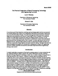
Figure 1 Scheme 1: micropen lithography (MPL) of a surfactant-templated mesophase. a, Simulation of 3D, binary ¯uid pattern dispensed on a ¯at substrate with the following parameters: pen ori®ce, 50.0 mm; substrate speed, 2.5 cm s-1; and ¯uid injection rate (inlet velocity), 4.0 cm s-1. Colour contours represent evaporation-induced, 3D gradients in alcohol composition. Residence times for ¯uid elements entering at the pen ori®ce and leaving at section 3 ranged from 0.23 to 0.30 ms. Fluid was modelled as 54 vol.% ethanol and 46 vol.% non-volatile phase with Reynolds number Re = 1.25 and Ca = 0.000833. An ad hoc value of 458 was chosen for the static contact angle. Note that this angle persists at all points on the dynamic contact line because of the dominance of surface
tension at this low value of Ca. b, The initially homogeneous sol metered on to the moving substrate experiences preferential evaporation of alcohol creating a complex 3D (longitudinal and radial) gradient in the concentrations of water and non-volatile surfactant and silicate species. Progressive enrichment of silica and surfactant induces micelle formation and subsequent growth of silica±surfactant mesophases inward from the liquid±vapour interface as recently demonstrated for aerosols23. The numerical method utilized for a and b consisted of a 3D ®nite-element discretization of the Navier±Stokes equations augmented with a 3D boundary-®tted mesh motion algorithm to track the free surface30,31. Special relations at the 3D dynamic wetting line were also applied.
Scheme 1 (Fig. 1) schematically illustrates direct writing of a mesoscopically ordered nanostructure, using micropen lithography, MPL17. Figure 2a shows a macroscopic pattern formed in several seconds by MPL of a rhodamine-B-containing solution on a hydrophilic surface. The inset in Fig. 2a shows the corresponding ¯uorescence image of several adjacent stripes acquired through a 610-nm bandpass ®lter, demonstrating retention of rhodamine-B functionality, and the transmission electron microscopy (TEM) image (Fig. 2b) reveals the ordered pore structure characteristic of a cubic thin-®lm mesophase. The MPL line width can vary from micrometres to millimetres. It depends on such factors as pen dimension18, wetting characteristics, evaporation rate, capillary
number (Ca = ink viscosity ´ substrate speed/surface tension) and ratio of the rates of ink supply and withdrawal (inlet velocity/ substrate velocity). The effect of wetting has been demonstrated by performing MPL on substrates prepatterned with hydrophobic, hydrophilic or mixed self-assembled monolayers (SAMs). Generally, a
b
3 mm a
b
c
1 mm
30 nm 25 nm
Figure 2 Meandering patterned mesophase created by MPL. a, Optical micrograph of patterned rhodamine-B-containing silica mesophase deposited on an oxidized [100]oriented silicon substrate at a speed of 2.54 cm s-1. Inset is a ¯uorescence image of rhodamine-B emission acquired through a 610-nm bandpass ®lter, demonstrating retention of rhodamine-B functionality. b, Representative TEM micrograph of a fragment of the patterned rhodamine-B-containing ®lm corresponding to a [110]-oriented cubic mesophase with lattice constant a = 10.3 nm. The sol was prepared by adding 0.01 wt% rhodamine-B to a silica/4wt% Brij-56 sol. The TEOS:EtOH:water:HCl:Brij-56:rhodamine-B molar ratio = 1:22:5.0:0.004:0.075:2.6 ´ 10-5. NATURE | VOL 405 | 4 MAY 2000 | www.nature.com
Figure 3 Patterned dot arrays created by ink-jet printing, IJP. a, Optical micrograph of a dot array created by IJP of standard ink (Hewlett-Packard Co.) on a non-adsorbent surface. b, Optical micrograph of an array of hydrophobic, mesoporous silica dots created by evaporation-induced silica±surfactant self-assembly during IJP on an oxidized [100]-oriented silicon substrate followed by calcination. c, Representative TEM micrograph of a dot fragment prepared as in b. The sol was prepared with molar ratio TEOS:TFTS:EtOH:water:HCl:Brij-56 = 1:0.05:22.0:5.0:0.004:0.075. The dot pattern used in a and b was designed using Microsoft PowerPoint 98 software. The printing rate was approximately 80 dots s-1 and printer resolution 300 dots per inch. The resolution achieved compared to standard ink and our ability to selectively functionalize the ink suggest applications in display technologies.
© 2000 Macmillan Magazines Ltd
57
letters to nature
line widths are reduced by increasing the contact angle and by reducing the pen ori®ce dimension and inlet/substrate velocity ratio. The advantages of MPL are that we can use any desired combination of surfactant and functional silane as ink to print selectively different functionalities at different locations. Furthermore, we can use computer-aided design (CAD) to de®ne arbitrary 2D patterns that can be written on arbitrary surfaces. For example, we have demonstrated writing rhodamine-containing mesophases (refractive index n = 1.2±1.3) on aerogel19 and emulsion-templated thin ®lms (n = 1.03±1.10), thereby directly de®ning optical waveguide structures potentially useful for lasing20. MPL is best suited to write continuous patterns. Patterned macroscopic arrays of discrete mesostructures can be obtained readily by combining EISA with aerosol processing schemes like ink-jet printing, IJP21,22. Figure 3b shows an optical micrograph of an array of hydrophobic, mesoporous spots formed on a silicon substrate by IJP of a TFTS-modi®ed ink. The IJP process dispenses the ink (prepared as for MPL) as monosized, spherical aerosol droplets. On striking the surface, the droplets adopt a new shape that balances surface and interfacial energies. Accompanying evaporation creates within each droplet a gradient in surfactant concentration that drives radially directed silica±surfactant selfassembly inward from the liquid±vapour interface23. The TEM micrograph (Fig. 3c) shows the ordered mesoporosity of a calcined, ¯uoroalkylated silica mesophase formed by IJP. The link to 58
and nitrogen adsorption±desorption isotherm (inset B, curve a) acquired for the thin-®lm specimen using a surface acoustic wave32 (SAW) technique. The dye conjugation reaction (2) was conducted by immersion in a 0.00002 mM solution of 5,6-FAM, SE (Table 1) prepared in dimethylsulphoxide (DMSO) followed by exhaustive, successive washing in DMSO, ethanol and water. The SAW-based nitrogen adsorption±desorption isotherm of the dye-conjugated mesoporous ®lm is shown in inset B, curve b, con®rming its pore accessibility. BET analyses of the sorption isotherms indicate that the dye conjugation reaction reduces the surface area from 750 to 545 m2 g-1 and the hydraulic radius from 2.2 to 2.1 nm, but pore accessibility is completely retained as evident from combined TEM, SAW and ¯uorescence-imaging results (Fig. 5a).
a
c
Increasing pH 4.8
7.7
12
200 µm b Intensity
Figure 4 Scheme 2: patterned functional mesostructure formed by selective de-wetting. Using microcontact printing or electrochemical desorption techniques, substrates are prepared with patterns of hydrophilic, hydroxyl-terminated SAMs and hydrophobic methyl-terminated SAMs. Preferential ethanol evaporation during dip-coating (1), causes water enrichment and selective dewetting of the hydrophobic SAMs. Correspondingly ®lm deposition occurs exclusively on the patterned hydrophilic SAMs. The sol was prepared by adding aminopropyltrimethoxysilane (NH2(CH2)3Si(OCH3)3, APS) to a silica/4wt% Brij-56 sol, resulting in a ®nal molar ratio TEOS:APS:EtOH:water:HCl:Brij-56 = 1:0.8:22:5.0:0.011:0.075. Selective dewetting followed by calcination results in a patterned, amine-functionalized, cubic mesoporous ®lm as is evident from the plan-view TEM micrograph (inset A), showing a [100]-oriented cubic mesophase with a = 10.3 nm
Films pH 12 7.0 5.5 4.8
Solutions pH 12 7.0 5.5 4.8
50 nm
480 510 540 570 600 630 480 510 540 570 600 630
Wavelength (nm) Figure 5 Patterned pH-sensitive ¯uidic system. a, Fluorescence image of three adjacent 5,6-FAM, SE-conjugated pore channel networks after introduction of aqueous solutions prepared at pH 4.8, 7.7 or 12.0. Patterned dye-conjugated thin ®lm mesophases were prepared according to scheme 2 (Fig. 4). Aqueous solutions of varying pH were introduced on the terminal pads (Fig. 4) and transported into the imaging cell by capillary ¯ow. Image was acquired using a Nikon Diaphot 300 inverted microscope and 520-nm bandpass ®lter. b, Fluorescence spectra of 5,6-FAM, SE-conjugated mesoporous ®lms upon exposure to aqueous solutions of pH 4.8, 7.7 and 12.0. Shown for comparison are ¯uorescence spectra of 0.1 mM solutions of 5,6-FAM, SE prepared in aqueous solutions of pH 4.8, 7.7 and 12.0. The similarity of the two sets of spectra con®rms the maintenance of dye functionality upon conjugation within the mesoporous channel system. c, Crosssectional TEM micrograph of the patterned, dye-conjugated thin-®lm mesophase, providing evidence of the 3D pore channel network.
© 2000 Macmillan Magazines Ltd
NATURE | VOL 405 | 4 MAY 2000 | www.nature.com
letters to nature computer-aided design (see Supplementary Information Fig. 4), greater printing resolution achieved compared to standard ink (see Fig. 3a), and our ability to selectively functionalize the ink, suggest applications in sensor arrays and display technologies. MPL and IJP are serial techniques. In situations where it is desirable to create an entire pattern with the same functionality, it might be preferable to employ a parallel technique in which the deposition process occurred simultaneously in multiple locations. Scheme 2 (Fig. 4) illustrates dip-coating on patterned SAMs. This rapid, parallel procedure uses microcontact printing24 or electrochemical patterning25 of hydroxyl- and methyl-terminated SAMs to de®ne hydrophilic and hydrophobic patterns on the substrate surface. Then, using inks identical to those employed for MPL and IJP, preferential ethanol evaporation during dip-coating enriches the depositing ®lm in water, causing selective de-wetting of the hydrophobic regions and ensuring self-assembly of silica±surfactant mesophases exclusively on the hydrophilic patterns. In this fashion, multiple lines, arrays of dots, or other arbitrary shapes, can be printed in seconds (see Fig. 5 in Supplementary Information). Recent density functional theory calculations26 have established the ultimate resolution of this differential wetting technique to be 1±2 nm. Scheme 2 (Fig. 4) illustrates the formation of a patterned propylamine-derivatized cubic mesophase by selective de-wetting followed by calcination to remove the surfactant templates (the organosilane used was aminopropyltrimethoxysilaneÐcompound 3 in Table 1.) The TEM micrograph (Fig. 4, inset A) and N2-sorption isotherm (based on surface acoustic wave, SAW, measurements; Fig. 4, inset B) provide evidence of the mesostructural order and proof of the accessibility of the mesoporosity to the vapour phase. In order to make a pH-sensitive ¯uidic system, the covalently bound propyl-amine ligands were conjugated with a pH-sensitive dye, 5,6carboxy¯uorescein, succinimidyl ester (5,6-FAM, SE) introduced in the pore-channel network of the cubic mesophase. After removal of any non-covalently-bonded dye, the uniform, continuous porosity of the amine-derivatized and dye-conjugated ®lms was con®rmed by TEM (Fig. 5c) and the corresponding SAW-based nitrogen sorption isotherm (Fig. 4, inset B). The slight reduction in ®lm porosity after dye conjugation re¯ects the volume occupied by the attached dye moieties. The patterned, dye-conjugated array was used to monitor the pH of ¯uids introduced at terminal pads and transported by capillary ¯ow into an imaging cell (scheme 2, Fig. 4). Figure 5a shows the ¯uorescence image of an array contacted with three different aqueous solutions prepared at pH 4.8, 7.7 and 12.0. Figure 5b shows the corresponding emission spectra. Comparison with solution data (Fig. 5b) indicates that dye molecules covalently attached to the mesoporous framework retain similar functionality to those in solution. The combined ¯uorescence image (Fig. 5a) and plan-view and cross-sectional TEM micrographs (Figs 4 and 5c) of the patterned dye-conjugated ®lm demonstrate the uniformity of macro- and meso-scale features achievable by this evaporationinduced, de-wetting and self-assembly route. In comparison, ®lms formed slowly (2±24 h) by nucleation and growth of thin-®lm mesophases on patterned SAMs2 were observed to have nonhomogeneous, globular morphologies unsuitable for ¯uidic or photonic systems. We also note that in this case the mesoporous ®lm formed on the hydrophobic regions. We believe that the evaporation-induced self-assembly process described here, and its elaboration in three different printing procedures, holds great promise for rapid prototyping of functional ¯uidic and photonic devices, along with displays and sensor arrays. Compared to alternative approaches like micromoulding in capillaries, printing is considerably faster (seconds compared to 12 hours) and avoids the need for moulds, masks and resists. By using a spectrum of functional inks and interfacing with commercially available software, computer-aided design and rapid transcription of functional microsystems may soon be achievable. M NATURE | VOL 405 | 4 MAY 2000 | www.nature.com
Methods Experimental procedures Precursor solutions used as inks were prepared by addition of surfactants (cationic, CTAB; CH3(CH2)15N+(CH3)3Br- or non-ionic, Brij-56; CH3(CH2)15 ±(OCH2CH2)10 ±OH), organosilanes (R9Si(OR)3, see Table 1), or organic molecules (see Table 1) to an acidic silica sol prepared from TEOS [Si(OCH2CH3)4] (A2**). The acid concentration employed in the A2** synthesis procedure was chosen to minimize the siloxane condensation rate, thereby promoting facile self-assembly during printing27. In a typical preparation, TEOS, ethanol, water and dilute HCl (mole ratios: 1:3.8:1:5´10-5) were re¯uxed at 60 8C for 90 min. The sol was diluted with 2 volumes of ethanol followed by further addition of water and HCl. Organosilanes (R9±Si(OR)3, where R9 is a non-hydrolysable organic functional ligand) were added followed by surfactants and (optionally) organic additives (see Table 1). Surfactants were added in requisite amounts to achieve initial surfactant concentrations c0 ranging from 0.004 to 0.23 M (c0 p c.m.c.). The ®nal reactant molar ratios were: 1 TEOS: 22 C2H5OH: 5 H2O: 0.093 - 0.31 surfactant: 0.039 - 0.8 organosilanes: 2.6 ´ 10-5 organic additives. For the ethane-bridged silsesquioxane, (RO)3Si±(CH2)2 ±Si(OR)3 (6 in Table 1), the neat precursor was diluted in ethanol and mixed with 1±8 wt% CTAB or Brij-56 surfactant followed by addition of an aqueous solution of HCl. The ®nal reactant molar ratios were: Si:EtOH:H2O:HCl:surfactant = 1:22:5:0.004:0.054±0.18. Co-hydrolysis of organosilanes with TEOS in the initial A2** sol preparation generally resulted in disordered worm-like mesostructures28. After pattern deposition and drying, the surfactant templates were selectively removed by calcination in a nitrogen atmosphere at a temperature suf®cient to decompose the surfactant molecules (,350 8C) without degrading the covalently bound organic ligands R9 (con®rmed by 29Si and 13C MAS NMR spectroscopy) or by solvent extraction.
Patterning procedures Micropen lithography was performed using a Model 400a micropen instrument (Ohmcraft Inc.). The pen ori®ce was 50 mm and the writing speed was 2.54 cm s-1. The pattern was designed using AutoCAD 14.01 (Autodesk, Inc.) software. Ink-jet printing was performed using a Model HP DeskJet 1200C printer (Hewlett-Packard Co.). The pattern was designed using Microsoft PowerPoint 98 software. Dip-coating of patterned (hydrophilic/hydrophobic) substrates was performed at a withdrawal speed of 7.6±51 cm min-1 under ambient laboratory conditions. Hydrophilic/ hydrophobic patterns were created by microcontact printing of hydrophobic, n-octadecyltrichlorosilane (CH3(CH2)17SiCl3) SAMs29 on hydrophilic silicon substrates (hydroxylated native oxide) or by a technique involving electrochemical desorption of a hydroxyl-terminated SAM prepared from 11-mercaptoundecanol (HO(CH2)11SH) from patterned, electrically isolated gold electrodes followed by immersion in a 1 mM ethanolic solution of 1-dodecanethiol, CH3(CH2)11SH (ref. 25). Received 23 August 1999; accepted 6 March 2000. 1. Xia, Y. & Whitesides, G. M. Soft lithography. Angew. Chem. Int. Edn Engl. 37, 550±575 (1998). 2. Yang, H., Coombs, N. & Ozin, G. A. Mesoporous silica with micrometer-scale designs. Adv. Mater. 9, 811±814 (1997). 3. Trau, M. et al. Microscopic patterning of orientated mesoscopic silica through guided growth. Nature 390, 674±676 (1997). 4. Yang, P. et al. Hierarchically ordered oxides. Science 282, 2244±2246 (1998). 5. Kresge, C., Leonowicz, M., Roth, W., Vartuli, C. & Beck, J. Ordered mesoporous molecular sieves synthesized by a liquid-crystal template mechanism. Nature 359, 710±712 (1992). 6. Burkett, S. L., Sims, S. D. & Mann, S. Synthesis of hybrid inorganic-organic mesoporous silica by cocondensation of siloxane and organosiloxane precursors. Chem. Commun. 1367±1368 (1996). 7. Fowler, C. E., Burkett, S. L. & Mann, S. Synthesis and characterization of ordered organosilica-surfactant mesophases with functionalized MCM-41-type architecture. Chem. Commun. 18, 1769±1770 (1997). 8. Lim, M. H., Blanford, C. F. & Stein, A. Synthesis and characterization of a reactive vinyl-functionalized MCM-41: Probing the internal pore structure by a bromination reaction. J. Am. Chem. Soc. 119, 4090±4091 (1997). 9. Liu, J. et al. Hybrid mesoporous materials with functionalized monolayers. Adv. Mater. 10, 161±165 (1998). 10. Lebeau, B., Fowler, C. E., Hall, S. R. & Mann, S. Transparent thin ®lms and monoliths prepared from dye-functionalized ordered silica mesostructures. J. Mater. Chem. 9, 2279±2281 (1999). 11. Imagaki, S., Guan, S., Fukushima, Y., Ohsuna, T. & Terasaki, O. Novel mesoporous materials with a uniform distribution of organic groups and inorganic oxide in their frameworks. J. Am. Chem. Soc. 121, 9611±9614 (1999). 12. Melde, B. J., Holland, B. T., Blanford, C. F. & Stein, A. Mesoporous sieves with uni®ed hybrid inorganic/organic frameworks. Chem. Mater. 11, 3302±3308 (1999). 13. Asefa, T., MacLachlan, M. J., Coombs, N. & Ozin, G. A. Periodic mesoporous organosilicas with organic groups inside the channel walls. Nature 402, 867±871 (1999). 14. Brinker, C. J., Lu, Y., Sellinger, A. & Fan, H. Evaporation-induced self-assembly: nanostructures made easy. Adv. Mater. 11, 579±585 (1999). 15. Yang, H., Coombs, N., Sokolov, I. & Ozin, G. A. Free-standing and oriented mesoporous silica ®lms grown at the air±water interface. Nature 381, 589±592 (1996). 16. Sellinger, A. et al. Continuous, self-assembly of organic±inorganic nanocomposite coatings that mimic nacre. Nature 394, 256±260 (1998). 17. Yang, P. et al. Direct-write precision resistors for ceramic packages. Mater. Res. Soc. Symp. Proc. 542, 159±164 (1999). 18. Piner, R. D., Zhu, J., Xu, F., Hong, S. & Mirkin, C. A. ``Dip-pen'' nanolithography. Science 283, 661± 663 (1999). 19. Prakash, S. S., Brinker, C. J., Hurd, A. J. & Rao, S. M. Silica aerogel ®lms prepared at ambient pressure by using surface derivatization to induce reversible drying shrinkage. Nature 374, 439±443 (1995).
© 2000 Macmillan Magazines Ltd
59
letters to nature 20. Yang, P. et al. Mirrorless lasing from mesostructured waveguides patterned by soft lithography. Science 287, 465±467 (2000). 21. Chang, S.-C. et al. Multicolor organic light-emitting diodes processed by hybrid inkjet printing. Adv. Mater. 11, 734±737 (1999). 22. Pede, D., Serra, G. & De Rossi, D. Microfabrication of conducting polymer devices by ink-jet stereolithography. Mater. Sci. Eng. C. 5, 289±291 (1998). 23. Lu, Y. et al. Aerosol-assisted self-assembly of spherical, silica nanoparticles exhibiting hexagonal, cubic and vesicular mesophases. Nature 398, 223±226 (1999). 24. Wilbur, J. L., Kumar, A., Biebuyck, H. A., Kim, E. & Whitesides, G. M. Microcontact printing of selfassembled monolayers: applications in microfabrication. Nanotechnology 7, 452±457 (1996). 25. Tender, L. M., Worley, R. L., Fan, H. & Lopez, G. P. Electrochemical patterning of self-assembled monolayers onto microscopic arrays of gold electrodes fabricated by laser ablation. Langmuir 12, 5515±5518 (1996). 26. Douglas Frink, L. J. & Sallinger, A. G. Wetting of a chemically heterogeneous surface. J. Chem. Phys. 110, 5969±5975 (1999). 27. Lu, Y. et al. Continuous formation of supported cubic and hexagonal mesoporous ®lms by sol-gel dipcoating. Nature 389, 364±368 (1997). 28. Tanev, P. T. & Pinnavaia, T. J. A neutral templating route to mesoporous molecular-sieves. Science 267, 865±867 (1995). 29. Bain, C. D. et al. Formation of monolayer ®lms by the spontaneous assembly of organic thiols from solution onto gold. J. Am. Chem. Soc. 111, 321±335 (1989). 30. Cairncross, R. A., Schunk, P. R., Baer, T. A., Rao, R. R. & Sackinger, P. A. A ®nite element method for free-surface ¯ows of incompressible ¯uids in three dimensions, Part 1: Boundary-®tted mesh motion. Int. J. Numer. Meth. Fluids (in the press). 31. Baer, T. A., Cairncross, R. A., Schunk, P. R., Rao, R. R. & Sackinger, P. A. A ®nite element method for free-surface ¯ows of incompressible ¯uids in three dimensions, Part 2: Dynamic wetting lines. Int. J. Numer. Meth. Fluids (in the press). 32. Frye, G. C., Ricco, A. J., Martin, S. J. & Brinker, C. J. in Better Ceramics Through Chemistry III (eds Brinker, C. J., Clark, D. E. & Ulrich, D. R.) 349±354 (Materials Research Society, Reno, Nevada, 1988).
Supplementary Information is available on Nature's World-Wide Web site (http://www.nature.com) or as paper copy from the London editorial of®ce of Nature.
Acknowledgements We thank R. Assink for performing NMR experiments, P. Yang for technical assistance with micropen lithography, and K. Burns for technical illustrations. TEM investigations were performed in the Department of Earth and Planetary Sciences at the University of New Mexico. Sandia is a multiprogram laboratory operated by Sandia Corporation, a Lockheed-Martin Company, for the US Department of Energy (DOE). This work was supported by the US DOE Basic Energy Sciences Program, the Sandia National Laboratories Laboratory-Directed Research and Development Program, the Defense Advanced Research Projects Agency Bio-Weapons Defense Program, and the US Department of Defense Of®ce of Naval Research. Correspondence and requests for materials should be addressed to C.J.B. (e-mail:
[email protected]).
................................................................. Large differences in tropical aerosol forcing at the top of the atmosphere and Earth's surface S. K. Satheesh & V. Ramanathan
for the winters of 1998 and 1999 decreased at the ocean surface by 12 to 30 Wm-2, but only by 4 to 10 Wm-2 at the top of the atmosphere. This threefold difference (due largely to solar absorption by soot) and the large magnitude of the observed surface forcing both imply that tropical aerosols might slow down the hydrological cycle. During December to April of each year, the tropical IndianOcean/Atmosphere system acts as a natural experiment for observing the radiative forcing by anthropogenic aerosols7. The gaseous and particulate pollutants emitted by the Indian sub-continent and the south Asian region are transported over the entire north Indian Ocean by the persistent northeastern low-level monsoonal ¯ow reaching as far south as 58 to 108 S (refs 7±11). The Indian Ocean Experiment, INDOEX7, was organized to assess the climatic and chemical in¯uence of anthropogenic aerosols in this region. This focused international experiment has been collecting data from ships, satellites and surface stations since 1996, and culminated in the intensive ®eld phase conducted during January to March 1999. The Kaashidhoo Climate Observatory (KCO)7,8, established as part of INDOEX in the island of Kaashidhoo at 4.9658 N, 73.4668 E about 500 km southwest of the southern tip of India, has been continually measuring the aerosol chemical, radiative and microphysical properties since February 1998. During the winter monsoon, the air mass over KCO mostly (about 90% of the time) originates from the Indian and south Asian sub-continents11. Coincident with the KCO observations are the radiation budget data from NASA's Clouds and Earth's Radiant Energy system (CERES) satellite, with an absolute accuracy of 0.2% or better, with a comparable precision12,13. The KCO data, along with several ship-borne measurements, have been documented extensively8±11. The data have also been used to develop a detailed aerosol± radiation model8. Here we compare the results of this model with the observed aerosol forcing. The model simulates the observed surface and TOA solar ¯uxes to within a few per cent (ref. 8). The aerosol columnar optical depth at 0.5 mm wavelength (tv) ranges from 0.2 to 0.7 and undergoes signi®cant daily, monthly and inter-annual variability (Fig. 1), and is a good index for the overall solar radiative effect of aerosols. The mean value of tv shown in Fig. 1 during February±March 1999 was ,0.41 compared to the corresponding value of 0.16 during 1998. The variability is much higher at smaller wavelengths (,0.34 mm) compared to near-infrared wavelengths (,1 mm), indicating that the increase in aerosol optical depth is dominated by sub-micrometre particles typical of anthropogenic sources. The KCO aerosol measurements8 reveal that sulphate and ammonium are responsible for 29% of the observed optical depth (tv), sea-salt and nitrate about 17%, mineral dust about 15%, and the inferred soot, organics, and ¯y ash contribute respectively 11%, 20% and 8%. The single scattering albedo, q0 (where q0 scattering=scattering absorption), for the composite
Center for Clouds, Chemistry, and Climate (C4), Scripps Institution of Oceanography, University of California at San Diego, La Jolla, California 92093 USA ..............................................................................................................................................
The effect of radiative forcing by anthropogenic aerosols is one of the largest sources of uncertainty in climate predictions1±6. Direct observations of the forcing are therefore needed, particularly for the poorly understood tropical aerosols. Here we present an observational method for quantifying aerosol forcing to within 65 per cent. We use calibrated satellite radiation measurements and ®ve independent surface radiometers to quantify the aerosol forcing simultaneously at the Earth's surface and the top of the atmosphere over the tropical northern Indian Ocean. In winter, this region is covered by anthropogenic aerosols of sulphate, nitrate, organics, soot and ¯y ash from the south Asian continent7,8. Accordingly, mean clear-sky solar radiative heating 60
Figure 1 Temporal variation of aerosol optical depth. The ®gure shows aerosol optical depth at 500 nm wavelength for 1998 (open squares) and 1999 (®lled squares). During 1998, the observations are available only during February and March.
© 2000 Macmillan Magazines Ltd
NATURE | VOL 405 | 4 MAY 2000 | www.nature.com