A Genetic Algorithm Hardware Accelerator for VLSI Circuit Partitioning S. Areibi∗ and M. Moussa and G. Koonar School of Engineering, University of Guelph Guelph, Ontario, Canada N1G 2W1
Abstract In recent years there has been a great interest in accelerating time consuming algorithms that solve large combinatorial optimization problems [1]. The advent of high density field programmable gate arrays in combination with efficient synthesis tools have enabled the production of custom machines for such difficult problems. Genetic Algorithms (GAs) [13] are robust techniques based on natural selection that can be used to solve a wide range of problems, including circuit partitioning. Although, a GA can provide very good solutions for such problems the amount of computations and iterations required for this method is enormous. As a result, software implementations of GA can become extremely slow for large circuit partitioning problems. In this paper, an architecture for implementing GAs on a Field Programmable Gate Array (FPGA) is presented. The architecture employs a combination of pipelining and parallelization to achieve substantial speedups. The GA accelerator proposed in this paper achieves more than 100× improvement in processing speed over its counterpart software implementation.
Keywords — Combinatorial Optimization, Circuit Partitioning, Genetic Algorithms, VLSI CAD, Hardware Accelerators, Reconfigurable Computing.
1
Introduction
The last decade has brought an explosive growth in the technology for manufacturing integrated circuits. Integrated circuits with several million transistors are now common place. This manufacturing capability, combined with the economic benefits of large electronic systems, is forcing a revolution in the design of these systems and providing a challenge to researchers interested in integrated system design. As the size and complexity of digital systems increases, more computer aided design (CAD) tools are introduced into the hardware design process. A large subset of problems in VLSI CAD is computationally intensive, and future CAD tools will require even more accuracy and computational capabilities. The complexity of digital systems imposes two main limitations in design implementation: (i) due to the huge size of designed digital circuit, it cannot be implemented as a single device, (ii) electronic design automation (EDA) tools often cannot handle the complexity of the digital circuits with millions of transistors and therefore the runtime of software becomes unreasonably large. A means to solve these problems is to partition the entire circuit into a set of sub-circuits, which are then further processed with other design tools or are implemented as a single device. High-quality partitioning is also critical in high-level synthesis. To be useful, high-level synthesis ∗
[email protected], This research is partially supported by a Natural Sciences and Engineering Research Council of Canada (NSERC) operating grant (OGP 0043417).
algorithms should be able to handle very large systems. Typically, designers partition high-level design specifications manually into procedures, each of which is then synthesized individually. Circuit partitioning is an NP-hard problem [9] and therefore no algorithm exists to solve the problem exactly (i.e. locate the global optimal solution) in polynomial time. A typical solution is to resort to heuristic based search techniques to solve the problem in reasonable time. Recently, four approaches have emerged for handling such complex combinatorial optimization problems: Simulated Annealing [16], Genetic Algorithms [13], Tabu Search [10], and GRASP [7]. The distinguishing feature for these techniques is the way they attempt to simulate some naturally-occurring process. Even with these search techniques, theoretical limits exist. A worthwhile avenue for research relative to combinatorial algorithm development involves accelerating these meta-heuristics by mapping them in hardware [20]. An emerging technology capable of providing high computational performance on a diversity of applications is reconfigurable computing, also known as adaptive computing, or FPGA-based computing. The evolution of reconfigurable computing systems has been mainly considered as a hardware-oriented design. Research has been focusing on configuring the hardware to implement a particular algorithm and on developing hardware devices that can be efficiently reconfigured for particular applications. The advances in reconfigurable computing architecture, in algorithm implementation methods, and in automatic mapping methods of algorithms into hardware and processor spaces form together a new paradigm of computing and programming that has often been called ‘Computing in Space and Time’ or ‘Computing without Computer’ [20]. The main goal of this paper is to present an architecture for implementing Genetic Algorithm (GA) that employs a combination of pipelining and parallelization to achieve adequate speedups. The architecture feasibility is demonstrated by solving the circuit-partitioning problem using hardware based GA. The paper also compares a hardware based GA with a software based implementation.
1.1
Contributions and Paper Outline
The main contributions of this paper can be summarized as follows: (i) development of an efficient Genetic Algorithm hardware accelerator to solve the problem of VLSI circuit partitioning that achieves more than 100 times improvement in processing speed as compared to a software implementation, (ii) the paper provides an example of a flexible reconfigurable computing architecture that can be re-used to solve other problems such as circuit placement, routing e.t.c. The paper is organized as follows: In Section 2 some background on Genetic Algorithms and Reconfigurable Computing will be presented. The main architecture of the GA accelerator is explained in detail in Section 3. Simulations of the proposed architecture and results based on comparison with the software implementation are introduced in Section 4. Actual mapping of the GA accelerator on a reconfigurable Platform and analysis of the results obtained are introduced in Section 5. Finally, Section 6 presents conclusions and possible avenues for future work.
2
Background
This section begins with a detailed description of circuit partitioning, Genetic Algorithms and reconfigurable computing. Previous work on hardware based GAs with specific architectures is also presented.
2
2.1
Overview of Circuit Partitioning
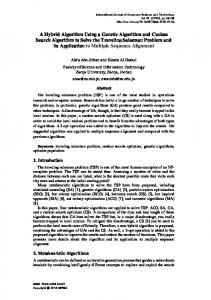
Circuit partitioning is the task of dividing a circuit into smaller parts [6]. It is an important aspect of layout for several reasons. Partitioning can be used directly to divide a circuit into portions that are implemented on separate physical components, such as printed circuit boards or Integrated Circuits. The objective is to partition the circuit into parts such that the sizes of the components are within prescribed ranges and the complexity of connections between the components is minimized [3]. The concept of circuit partitioning is illustrated in Figure 1 where the circuit consists of five modules and four nets. The circuit is to be partitioned into two blocks. The initial solution before swapping modules leads to three nets being cut. After swapping modules between the two blocks we end up minimizing the number of signal nets that interconnect the components between the blocks (i.e. one cut). A natural way of formalizing the notion of wiring complexity is to attribute to each net Initial Solution
3 Nets Cut
1 Net Cut After swapping
NET 1
1
2 NET 3 BLOCK(1)
NET 1
3
4 NET 2
5
3
NET 4
2
NET 2
BLOCK(2)
BLOCK(1)
module 1 and 3
1
4
NET 3
5
NET 4
BLOCK(2)
Figure 1: Illustration of Circuit Partitioning in the circuit some connection cost, and to sum the connection costs of all nets connecting different components. A more important use of circuit partitioning is to divide up a circuit hierarchically into parts with divide-and-conquer algorithms for placement, floor-planning and other layout problems. Here, cost measures to be minimized during partitioning may vary, but mainly they are similar to the connection cost measures for general partitioning problems.
2.2
Local Search Based Techniques
It has been shown that graph and network partitioning problems are NP-Complete [9]. Therefore, attempts to solve these problems have concentrated on finding heuristics which yield approximate solutions in polynomial time. Heuristic methods can produce good solutions (possibly even an optimal solution) quickly. Often in practical applications, several good solutions are of more value than one optimal one. The first and foremost consideration in developing heuristics for combinatorial problems of this type is finding a procedure that is powerful and yet sufficiently fast to be practical (recent Integrated Circuits contain over 100 million gates and nets). For the circuit partitioning problem several classes of algorithms were developed to generate good partitions. Kernighan and Lin (KL) [15] described a successful heuristic procedure for graph partitioning which became the basis for most module interchange-based improvement partitioning heuristics used in general. Their approach starts with an initial bisection and then involves the exchange of pairs of vertices across the cut of the bisection to improve the cut-size (as illustrated in Figure 1). Fiduccia and Mattheyses (FM) [8] modified the Kernighan and Lin algorithm by suggesting to move one cell at a time instead of exchanging pairs of vertices, and also introduced the concept of preserving balance in the size of blocks. The main problem facing traditional local search heuristic methods is the inferior quality of solutions they produce. This is mainly due to locality and lack of ability to explore the solution space effectively and therefore they get trapped in local minima. 3
2.3
A Genetic Algorithm for VLSI Circuit Partitioning
Genetic Algorithms are natural selection-based optimization techniques [12] that are capable of exploring the parameter space. The algorithms are called genetic because the manipulation of possible solutions resembles the mechanics of natural selection. These algorithms which were introduced by Holland [13] in 1975 are based on the notion of propagating new solutions from parent solutions, employing mechanisms modeled after those currently believed to apply in genetics. The best offspring of the parent solutions are retained for a next generation of mating, thereby proceeding in an evolutionary fashion that encourages the survival of the fittest. There are essentially four basic Nets Cut TotalMods = 7 totalNets = 6 TotalBlks = 2
M1
M2
M4
M8
M3
M5
M6
M7
Block 0
Block 1
M1
M2
M3
M4
M5
M6
M7
M8
0
0
1
0
1
1
1
0
Fitness = TotalNets − NetsCut =6−2=4
Group Number Encoding
Figure 2: Chromosome Representation for Circuit Partitioning components necessary for the successful implementation of a Genetic Algorithm. At the outset, there must be a code or scheme that allows for a bit string representation of possible solutions to the problem. Figure 2 illustrates group-number encoding where the j th integer ij ∈ {1, . . . , k} indicates the group number assigned to object j (where k is the number of blocks). Next, a suitable function must be devised that allows for a ranking or fitness assessment of any solution. This fitness influences the selection process for the next generation. For the circuit partitioning problem, the evaluation function measures the worth (number of cuts) of any chromosome (partition) for the circuit to be solved. The fitness of any chromosome for circuit partitioning (as seen in Figure 2) is measured as follows: F itness = T otN umN ets − CutSize. The third component, contains transformation functions that create new individuals from existing solutions in a population. The crossover and mutation operators (to be explained later) are crucial to any GA implementations. Finally, the fourth module contains techniques for population initialization, generation replacement, and parent selection techniques. The initialization techniques generally used are based on pseudo-random methods. The algorithm will create its starting population by filling it with pseudo-randomly generated bit strings. Strings are selected for mating based on their fitness, those with greater fitness are awarded more offspring than those with lesser fitness. Parent selection techniques that are used, vary from stochastic to deterministic methods. The probability that a string i is selected for mating is p i , “the ratio of the fitness of string i to the i sum of all string fitness values”, pi = Pf itness . The ratio of individual fitness to the fitness sum f itness j
j
denotes a ranking of that string in the population. Generation replacement techniques are used to select a member of the old population and replace it with the new offspring. The quality of solutions obtained depends on the replacement scheme used. The GA operations selection, crossover and mutation primarily involve random number generation, copying, and partial string exchange. Thus 4
they are powerful tools which are simple to implement. Its basis in natural selection allows a GA to employ a “survival of the fittest” strategy when searching for optima. The use of a population of points helps the GA avoid converging to false peaks (local optima) in the search. Figure 3 illustrates a Genetic Algorithm implementation for circuit partitioning. The GA starts with several alternative solutions to the optimization problem, which are considered as individuals in a population. These solutions are coded as binary strings, called chromosomes. The initial population is constructed randomly. These individuals are evaluated, using the partitioning-specific fitness function. The GA then uses these individuals to produce a new generation of hopefully better solutions. In each generation, two of the individuals are selected probabilistically as parents, with the selection probability proportional to their fitness. Crossover is performed on these individuals
1. Encode Solution Space for circuit 2.(a) set pop size, max gen, gen=0; (b) set cross rate, mutate rate; 3. Initialize Population. 4. While max gen ≥ gen Evaluate Fitness (# of cuts) For (i=1 to pop size) Select (mate1,mate2) if (rnd(0,1) ≤ cross rate) child = Crossover(mate1,mate2); if (rnd(0,1) ≤ mutate rate) child = Mutation(); Repair child if necessary End For Add offsprings to New Generation. gen = gen + 1 End While 5. Return best chromosomes.
Figure 3: A Genetic Algorithm for VLSI Circuit Partitioning to generate two new individuals, called offspring, by exchanging parts of their structure as seen in Figure 4a. Thus each offspring inherits a combination of features from both parents. The next step is mutation (as illustrated in Figure 4b) where an incremental change is made to each member of the population, with a small probability. This ensures that the GA can explore new features that may not be in the population yet. It makes the entire search space reachable, despite the finite population size. However an offspring may contain less than k groups; more-over, an offspring of two parents, both representing feasible solutions may be infeasible, since the constraint of having equal number of modules in each partition is not met. In this case a repair heuristic is invoked to modify chromosomes to become feasible.
2.4
Reconfigurable Computing Systems
Due to its potential to greatly accelerate a wide variety of applications, reconfigurable computing has become a subject of a great deal of research. Its key feature is the ability to perform computations in hardware to increase performance, while retaining much of the flexibility of a software solution. Reconfigurable systems [5] are usually formed with a combination of reconfigurable logic 5
Parents Selected According to their Fitness
P1
1 0 1 0 0
1
1
P2
0 0 0 1 1
1
0
One Point Crossover
C1
1 0 1
0 1
1
0
C2
0 0 0
1 0 1
1
’ C1
1 0 0 0 1 1 0
’ C2
1 0 0 1 0 1 1
Mutation Operator
Children after Mutation Children Created After Crossover
(a) Crossover Operator
(b) Mutation Operator
Figure 4: Crossover and Mutation Operators for Circuit Partitioning [2] and a general purpose microprocessor. The processor performs the operations that cannot be done efficiently in reconfigurable logic, while the computational cores are mapped to reconfigurable hardware. This reconfigurable logic can be supported by either FPGAs or other custom configurable hardware. Reconfigurable computing involves manipulation of the logic within the FPGA at runtime. In other words, the design of the hardware may change in response to the demands placed upon the system while it is running. Here, the FPGA acts as an execution engine for a variety of different hardware functions, some executing in parallel, others in serial. The design process in a reconfigurable hardware involves first partitioning the design into sections to be implemented on hardware and software. The portion of design which is to be implemented on hardware is synthesized into a gate level or register transfer level circuit description. This circuit is mapped onto logic blocks within the reconfigurable hardware during the technology mapping phase. These mapped blocks are then placed into a specific physical block within the hardware, and the different blocks of the circuit are connected using the routing resources available. Following compilation, the circuit is ready for configuration onto the hardware at run-time. Now-days, various tools are available which can automatically compile all these steps and the designer requires very little effort to use the reconfigurable hardware. The design steps for Reconfigurable Computing is illustrated in Figure 5.
2.5
Previous work on Hardware based GA
The past several years have seen a sharp increase of work on reconfigurable hardware systems. The key to the hardware implementation of the GA is to divide the algorithm into sub-sections and perform the latter using dedicated hardware modules in parallel. In evolutionary computation, evolutionary operations are applied to a large number of individuals (genes) repeatedly. The computation can be pipelined (a sequence of evolutionary operators) and parallelized by dedicated hardware, and thus high performance is expected. However, details of the operators depend on given problems and vary considerably. In [18], it was shown that a co-processor system with a Virtex FPGA can achieve high performance in evolutionary computations by utilizing the two features of an FPGA. First, agents in evolutionary computation models which are usually expressed using short bit-strings can be stored in distributed select RAMs of Virtex FPGAs very efficiently. Second, the partial reconfiguration and read-back functions of the FPGAs make it possible to exploit 6
DESIGN SPECIFICATIONS
DESIGN CONSTRAINTS
ALGORITHM DESIGN & ANALYSIS
SYSTEM ARCHITECTURE DESIGN (HW/SW Partitioning)
HW IP LIBRARY
SW IP LIBRARY
HDL CODING CO-VERIFICATION CO-VERIFIVATION
FUNCTIONAL SIMULATION
SW DEVELOPMENT
SYNTHESIS TIMING SIMULATION
PLACE/ ROUTE
HW/SW INTEGRATION
Figure 5: Design Steps for Reconfigurable Computing parallelism without thinking about circuits for data I/O. Gokhale [11] developed a programmable linear logic array called SPLASH that was applied to many areas, including one-dimensional pattern matching between DNA sequence and a library sequence. Splash greatly outperformed several more expensive alternatives, including the P-NAC, a CM-2 and a Cray-2. It consisted of 32 Xilinx XC3090 and 32 memory chip. Also in [17], it was shown that a hardware system with two FPGAs and SRAMs, achieved 50 times of speedup compared with a workstation (200MHz) in some evolutionary computation problems. The use of reconfigurable hardware for the design of GA was also seen in projects such as [22], [21], [23]. In Stephan Scott’s behavioral-level implementation of a GA [22], the targeted application was an optimization of an input function. In [21], a GA was designed and implemented on a PLD, using Altera hardware description language (AHDL). In [23], a number of GAs were designed and implemented in a text compression chip.
3
System Specifications and Architecture
This section describes an architecture of the Genetic Algorithm accelerator along with the functional description of each module. The GA accelerator proposed must maintain the following system specifications and constraints: 1. Area Utilization Efficiency: The design has to be implemented on a single FPGA, thus reducing the hardware resources needed. In order to further minimize the hardware resources, the area/gate utilization of the FPGA should be as small as possible. This would enable the implementation to be performed on a small-sized FPGA or additional blocks to be implemented on the same large-sized FPGA.
7
2. Design Flexibility: The design should be easily configured for different sized problems during synthesis. This ensures that the same RTL code can be used for a wide range of applications, thus making it easier for portability. In RTL code, this can be achieved by using generics or parameters, of which the hardware can be changed based upon the size of the application. These generics can be changed at the time of digital synthesis. 3. Modularity: The architecture should be split up into smaller modules, each designed to perform a well defined and well-partitioned function. This makes it easier to debug, understand, and also helps in the design-reuse methodology such as a local search accelerator can be integrated with it in the future to act as a Memetic [4] accelerator.
3.1
Representation of Circuit Partitioning
In order to solve the circuit-partitioning problem using GA, the following representation is used. Each chromosome contains a sequence of 1’s and 0’s, each bit corresponding to a distinct cell in the PARTITION 0
M0
M1
M2
PARTITION 1
M3
M4
M5
M6
M7
NET 1 M7 M6 M5 M4 M3 M2 M1 M0
1 1 1 1 0 0 0 0
CHROMOSOME REPRESENTATION
0 1 0 1 1 1 0 0
NET 1 REPRESENTATION
Figure 6: Representation of Chromosome and Net-list for Circuit Partitioning net-list. A ‘1’ at a location in the sequence indicates that the corresponding cell lies in partition 1. Similarly, a ‘0’ implies that the cell is present in partition 0 as shown in Figure 6. Therefore, the length of the chromosome is a function of the number of modules in the circuit. Since there are practical limitations to word sizes of physical memories, the chromosome is stored in memory in the form of smaller words. Words corresponding to one chromosome are stored consecutively. The net-list is stored into the net-list memory in a similar manner. Each net in the net-list has an entry in the net-list memory which is as wide as the number of modules. For each net, 1’s are placed in the bit positions corresponding to the modules to which the net is connected as shown in Figure 6.
3.2
System Architecture
The initial step of designing the GA accelerator involves a mapping from the software implementation into hardware. The proposed architecture (core) for implementing the genetic algorithm in hardware uses a processing-pipeline for performing the computationally extensive parts of the algorithm. The block diagram of the GA accelerator is shown in Figure 7. The current design is specifically optimized towards solving the circuit-partitioning problem. The design partitioning is performed in such a way that each block performs a well-defined function, thus making it easier to re-use some of the blocks for a different type of optimization problem. Since different blocks share accesses to the same memories, a memory-mux is used to multiplex the memory-accesses 8
Figure 7: Architecture of the Genetic Algorithm Processor from different blocks. In addition, the control registers are implemented as an independent block. These registers are accessible through the simple CPU interface. A common controller approach is followed in which a central Main Controller generates the control signals for all the other blocks in the design. Separate blocks are used to perform the selection, crossover, and fitness calculation. The Main Controller is used to schedule the operations of these blocks using an “enable/disable” signal for each block. Each block notifies the Main Controller when the task is completed using a “done” signal. Since fitness calculation is the most time consuming operation in the GA, the added complexity arising from the hardware implementation of fitness is out-weighed by the improvement in processing speed achieved over the software implementation of fitness calculation. The Selection Module selects the parents with good fitness from Fitness Memory and sends the addresses of the parents selected to the Crossover and Mutation Modules. The latter perform crossover and mutation on the parents. The Fitness Module generates fitness values for each of the generated chromosomes. The Control Registers are loaded with ‘legal’ values using the CPU interface. 3.2.1
Control Registers
The core uses a set of control registers which can be programmed using the CPU interface. The register address map is provided in Table 1. 1. CMLength Register, stores the chromosome length in terms of number of Chromosome memory data words CMDataWidth. 2. NetNum Register, stores the number of nets in terms of Netlist memory data words CMDataWidth. Note that the data word size of the net-list memory is the same as that for the chromosome memory. 3. PopSiz Register, stores the Population Size in terms of chromosome per population. 4. GenNum Register, stores the number of generations, which the core has to generate before sending the output population and fitness. 9
Address 0x00-0x01 0x02-0x03 0x04 0x05 0x06 0x07
Register CMLength NetNum PopSiz Gen Num CrossoverRate MutationRate
Size 2x8 2x8 1x8 1x8 1x8 1x8
Description Chromosome Length Number of nets Population size Generation Count Crossover rate Mutation rate
Table 1: Register Address Map
5. CrossoverRate Register, stores the Crossover rate ranging from 0 to 255. Percentage crossover rate is obtained by dividing this register value by 255. 6. MutationRate Register, stores the Mutation rate ranging from 0 to 255. Percentage Mutation rate is obtained by dividing this register value by 255. 3.2.2
Core Generics
The design is coded in VHDL and uses the generics shown in Table 2. These generics help in creating general models for many different configurations of inputs and outputs. Generics pass the information into a design description from its environment and helps to reconfigure. Therefore, testing can be done with different sets of data(different benchmarks). Generic Name FMAddrWidth FMDataWidth CMDataWidth CMField MaxNetNumBits
Description Fitness memory address width. This gives two times maximum size supported. Fitness memory data width. Chromosome memory data width. This represents word size of chromosome memory. Number of bits used to represent the length of chromosome. Number of bits used to represent maximum number of nets.
Default 9 8 8 8 8
Table 2: Generics Used in the Design
3.2.3
Core Memories
The external RAM modules used by the core (shown in Figure 7) are listed in Table 3. The Netlist Memory stores the input net-list while the Chromosome Memory stores the randomly generated chromosomes for parent and child population. The fitness of the old generation (i.e. parents) and new generation (i.e. children) of the whole population is stored in the Fitness Memory.
3.3
Selection Module
The selection module as shown in Figure 8 performs Tournament selection on the initial population by reading four random fitnesses from the Fitness memory and outputs the addresses of two parents 10
Memory
Size
Description
Netlist Memory
2(M axN etN umBits+CM F ield)
Chromosome Memory
2(F M AddrW idth+CM F ield+1) ×CMDataWidth
Stores a binary sequence length of chromosome for each net. Each bit denotes if that net is connected to a cell in the netlist or not. This is single address port RAM. stores population elements for the parent and child population. Address space is divided into two halves. Each stores either parent or child. This is dual address port RAM Stores fitness of parent and child It is also divided into two parts for storing parent and child. This is single address port RAM.
Fitness Memory
×CMDataWidth
2(F M AddrW idth+1) ×CMDataWidth
Table 3: Core Memories
corresponding to the better two of the four parents. The Selection Module upon receiving an active high SelectionEnb signal from the Main Controller performs the following functions: (i) Generates four random addresses for the fitness memory and reads four fitness values from either the low or high memory bank indicated by the HighBank signal. The selection module uses an instantiation of an LFSR based Random Number Generator [14]; (ii) Compares two pairs of fitnesses and selects the best from each pair; (iii) Latches the addresses of the best two fitnesses on the output signals Parent1Addr and Parent2Addr; (iv) Generates an active high pulse on the SelectionDone output signal. Internally, the Selection Module consists of a random number generator, a comparator for comparing unsigned integers, registers to latch the generated random addresses, and a control state machine. The control state machine generates control/enable signals for different blocks in the module.
3.4
Crossover & Mutation Module
The Crossover Module (shown in Figure 9) performs the crossover and mutation operations on the two parent chromosomes, the starting addresses of which are generated by the Selection Module. The Chromosome Memory is divided into two parts, namely the low bank, and the high bank. The parent population is stored into one of the banks and the child population generated by the Crossover and Mutation Module is stored into the other bank. When an active high pulse on CrossoverEnb input is received, the following functions are performed by the Crossover and Mutation Modules: (i) One word of the chromosome for each of the parents is read from the Chromosome memory based upon theParent1Addr and Parent2Addr and the chromosome-word counter is incremented; (ii) The Crossover Module generates a random crossover mask for each word of the parents. If the value of this random number is less than the crossover and mutation rates, these operations are performed, otherwise the parents are copied to the children. The resulted chromosomes are repaired based upon the number of cells present in each partition; (iii) A random number is generated which will select a random bit in a chromosome. The bit is flipped based upon the difference of number of 1’s and 0’s. (iv) The results of crossover and mutation are stored wordby-word into the Chromosome Memory. Internally, the Crossover Module consists of a chromosome 11
FMDataRd
FMAddrRd
FITNESS REGISTER DEMUX
RANDOM NUMBER GENERATOR FMRdEnb
FITNESS REGISTER1
FITNESS REGISTER2
FITNESS COMPARATOR
Main Controller Interface
ADDRESS REGISTER DEMUX
ADDRESS REGISTER1
SELECTION CONTROL STATE MACHINE
Control Registers
ADDRESS REGISTER2
ADDRESS SELECTION MUX
PARENT REGISTER DEMUX
PARENT REGISTER1
Parent1Addr
PARENT REGISTER2
Parent2Addr
Figure 8: Detailed Description of Selection Module
word counter, which is CMField bits wide and trivial combinatorial logic to perform the crossover and mutation operations as shown in Figure 10. A Random Number Generator is also instantiated within the module.
3.5
Fitness Module
The Fitness Module shown in Figure 11 computes the fitness of the randomly generated population during initialization. Once a complete new population is generated by the crossover and mutation module, the Fitness Module generates fitness values for each of the generated chromosomes. Upon receiving the FitnessEnb signal from the Main Controller, the Fitness Module performs the following functions: (i) For each net, determine if the present chromosome partitioning generates a cut. For each chromosome the fitness accumulator is reset to 0. The chromosome and the net are read word-by-word from the Chromosome and the Netlist Memory, respectively. For each word of the chromosome and the net, a simple bit-wise AND operation followed by OR operation is performed as shown in Figure 11; (ii) At any time during the computations of a net, if a cut exists, no further words are read from the memory. This eliminates the time wasted by reading redundant information from the Chromosome and Netlist Memories; (iii) A chromosome counter keeps track of the number of chromosomes processed. If this counter reaches PopSiz, FitnessDone signal is asserted signaling the end of Fitness generation to the Main Controller. No further processing is done until the FitnessEnb signal is asserted again by the Main Controller.
3.6
Main Controller Module
The Main Controller generates control signals for the rest of the blocks of the design. It reads the input net-list from the top-level inputs and loads it into the Netlist Memory. At the final generation,
12
MUX
MUTATION LOGIC MODULE
MUX CMDataRd
DELAY
CROSSOVER LOGIC MODULE
Child1Word
CMDataWr MUX
MUTATION LOGIC MODULE
MUX XoverMask
MUX
DELAY Child2Word
CrossoverRate X-OVER COMPARATOR
XoverEnable
RANDOM NUMBER GENERATOR
MutationMask
MUTATION COMPARATOR
MutationRate
MutationEnable
Concatenation Operator CHROMOSOME WORD COUNTER Parent1Addr CMAddrRd Parent2Addr
Child1Addr
CMAddrWr Child2Addr
Figure 9: Detailed Description of Crossover and Mutation Module
Parent1Word
Parent2Word
XoverMask
Child1Word
Child2Word
CROSSOVER LOGIC MODULE
ChromosomeIn
MutationMask
Parent1Bit Child1Bit
XOR
ChromosomeOut
XOR
Child2Bit Parent2Bit
MaskBit MUTATION LOGIC MODULE
Figure 10: Detailed Description of Crossover and Mutation Module Logic
13
Partition 1 Result Chromosome EN
8
AND
Netlist
OR
Latch
8
8
NetIn Partition1 NetIsCut AND
NetIn Partition2
AND
OR
+
Fitness
Latch
8 EN
Partition 0 Result
Net 1
Chromosome 1
0
0
1
0
1
0
1
1
1
0
1
0
1
0
1
0
Net 1
Chromosome 1
0
0
0
1
Bit-Wise AND
0
0
1
0
1
1
0
1
1
1
0
0
1
0
1
0
1
1
0
0
Bit-Wise AND
0
1
0
0
0
Bit-Wise OR
0
0
0
Bit-Wise OR
NetIn Partition1
NetInPartition2
Figure 11: Fitness Calculation
the Main Controller outputs the final population along with fitness of each chromosome. The pin diagram is introduced in Figure 12. It depicts the top level interface, memory interface, selection module interface, crossover module interface and fitness module interface. The Main Controller performs the following functions: (i) Starts reading the input net-list using the input handshake signals immediately after receiving the active high pulse on StartGA; (ii) Loads the net-list into the Netlist Memory, chromosomes and randomly generates an initial population which is stored in the Chromosome Memory; (iii) Iterates between the three functions of fitness calculation, chromosome selection, crossover and mutation operations until the generation counter reaches the maximum count loaded into GenNum control register. The state diagram of the Main Controller state machine is shown in Figure 13.
4 4.1
Simulated Performance and Comparison Simulation Setup
The proposed architecture was coded in VHDL. It was functionally verified by writing a testbench and simulating it using ModelSim and synthesizing it on Virtex xcv2000e using Xilinx ISE 5.1. The optimization criterion kept during synthesis was speedup. The benchmarks used to evaluate the performance of the GA partitioning are presented in Table 4. Small benchmarks were designed for design verification, thus removing the requirement of using a large FPGA. Chip1 and Chip3 circuits were taken from the work of Fiduccia & Mattheyses [8]. The Hardware GA accelerator was compared with the software implementation for all benchmarks with default GA parameters shown in Table 5.
4.2
Results
The results of the fitness (number of cuts) in software, for different benchmarks are shown in Table 6. This table describes the average and minimum fitness during initialization and at the final generation. It also highlights the best fitness encountered during the runs for different generations.
14
CMLength
NetNum
PopSiz
GenNum
Control Registers
HighBank SelectionEnb SelectionDone CrossoverEnb
Netlist In
CrossoverDone
Main Controller
PopOut
Child1Addr Child2Addr
PopOutVld
FitnessEnb FitnessDone
Fitness Memory Write Interface
NMDataRd
NMRdEnb
NMAddrRd
CMDataWr
CMWrEnb
CMDataRd
CMAddrWr
CMAddrRd
CMRdEnb
FMDataWr
FMWrEnb
GADone
Fitness Module Interface
FitnessOut
FMAddrWr
Crossover Module Interface
Top-level IO's
StartGA Netlist Vld
Selection Module Interface
Clk ResetN
Netlist Memory Read Interface
Chromosome Memory Read Interface
Figure 12: Pin Description of the Main Controller Module Circuit
Nodes
Nets
Pins
net9 mod10 net12 mod15 net15 mod10 Pcb1 Chip3 Chip1
10 15 10 24 199 300
9 12 15 32 219 294
22 30 48 84 545 845
Node Degree MAX x σ 3 2.2 0.4 3 2.0 0.5 9 4.8 2.3 7 3.5 1.35 5 2.73 1.28 6 2.82 1.15
Net Size MAX x 3 2.4 3 2.5 10 3.2 8 2.63 9 2.49 14 2.87
σ 0.49 0.50 1.94 1.19 1.25 1.39
Table 4: Benchmarks used as Test Cases
These results are compared with the hardware results for fitness. It can be seen that the hardware and software results for fitness are comparable in Table 7. The differences are due to different random number module implementations. The results obtained for different population sizes are given in Table 8. Tests were run assuming the clock frequency of 50MHz. The remaining GA parameters were assigned the default values given in Table 5. From the simulations results, it is clear that the hardware implementation is faster than the software version. The software results shown in Table 8 were achieved using SUN ULTRA10 440 MHz processor system. As seen, the speed increases to approximately 50 times the software implementation. This tremendous increase in speed for hardware implementation is mainly attributed to the fact that, during fitness evaluation, if a cut is determined for a net at any time, the remaining words for that net and the chromosome are not read from the memory. This eliminates the time wasted by reading redundant information from the Chromosome and Netlist Memories. The hardware processing speed can further be increased by increasing the Chromosome memory data bus width because this enables more computations to be performed in parallel. Synthesis results are shown in Table 9 where it is evident from the results that minimal hardware resources are utilized. Since the simulation results shown in Table 8 are obtained by assuming a 50 MHz clock frequency, the improvement in speed can be increased to more than 100 times the software implementation with a maximum
15
Reset GADoneInt= '1'
stIdle StartGA ='1'
stPreIdle stload Netlist PopCntDone='1'
RstHighBank ='1'; Rst all Counters LoadAddrCnt ='1'; AddrCntMax= NumOfNets*Clength;
if (NetlistVld =1) AddrCntEnb ='1'; NMAddrWrInt = AddrCnt; NMWrEnbInt ='1'; NMDataWrInt = Netlist;
AddrCntDone='1'
stOutputResults AddrCntRst ='1'; LoadAddrCnt = '1'; AddrCntMax=PSize*CLength;
stInitializePop CMCntEnb='1' PopCntEnb='1' CMRdEnbInt='1' PopOutInt=CMDataRd FMRdEnbInt='1' FitnessOutInt= FMDataRd PopOutVldInt= CMRdEnbIntD2
FitnessDone='1' && GenCntDone = '1'
stFitness FitnessDone='1' && GenCntDone = '0'
CrossoverDone='1' && ChildCntDone='1'
ToggleHighBank ='1'; ChildCntEnb ='1'; GenCntEnb ='1';
AddrCntDone='1'
FitnessEnb ='1'; GenerationCntEnb ='1'; ChildCntRst ='1';
SelectionEnb ='1';
stSelection
CrossoverDone='1' && ChildCntDone='0'
AddrCntEnb ='1'; GenerateRand ='1' CMAddrWrInt ='1'; CMWrEnbInt ='1'; CMDataWrInt=Rand(7:0);
SelectionDone='1'
CrossoverEnb ='1';
stCrossover
ChildCntEnb ='1';
Figure 13: State Diagram of Main Controller Module
Parameters Population Size Generation Count Crossover Rate Mutation Rate Crossover Type Selection Type
Parameter value 20 20 0.99 0.01 Uniform Tournament
Table 5: Default GA Parameters
Benchmarks
net9 mod10 net12 mod15 net15 mod10 Pcb1 Chip3 Chip1
Initial Average Fitness 6 7 11 20 123 184
Initial Minimum Fitness 3 4 8 16 107 172
Final Average Fitness 1 1 4 9 17 38
Final Minimum Fitness 1 1 4 9 12 27
Table 6: Software Fitness Results
16
Best Fitness 1 1 4 9 10 20
Benchmarks
net9 mod10 net12 mod15 net15 mod10 Pcb1 Chip1 Chip3
Initial Software Average Fitness 6.4 7.5 11.5 20.0 184 123
Initial Software Minimum Fitness 3.0 4.0 8.0 16.0 172 107
Final Software Average Fitness 1.0 1.0 4.2 9.0 38 17
Final Software Minimum Fitness 1.0 1.0 4.0 9.0 27 12
Best Software Fitness
Best Hardware Fitness
1.0 1.0 4.0 9.0 20 10
1.0 2.0 4.0 10.0 22 12
Table 7: Hardware Fitness Results
Benchmarks
Population Size
Software Time (ms)
net9 mod10 Nnets=9 Nmods=10 net12 mod15 Nnets=12 Nmods=15 net15 mod10 Nnets=15 Nmods=10 Pcb1 Nnets=32 Nmods=24 Chip1 Nnets=294 Nmods=300 Chip3 Nnets=239 Nmods=274
20 60 100 20 60 100 20 60 100 20 60 100 20 60 100 20 60 100
100 300 600 200 400 700 200 500 800 200 700 1100 1700 4900 8800 1200 3800 5700
Hardware Time(ms) CMDataWidth CMDataWidth (8bit) (16 bit) 0.53 0.45 1.59 1.34 2.58 2.24 0.67 0.57 2.01 1.70 3.36 2.84 0.82 0.69 2.44 2.06 4.08 3.44 1.86 1.63 5.58 4.82 9.30 7.20 73.56 40.50 218.24 122.25 362.92 203.60 38.41 23.23 114.32 69.36 189.21 115.32
Table 8: Performance Results for Hardware/Software Implementations
17
Device Slices CLB’s Equivalent Gate Count Max Clock Frequency
Virtex xcv2000e 334 out of 19200 (1.7%) 167 6044 123 MHz
Table 9: Synthesis Report
tolerable clock frequency of 123 MHZ. It is important to notice that the software implementation can be accelerated if a parallel/distributed implementation was carried out. However, the speedup achieved will be limited due to the synchronization between the processors involved.
5 5.1
System Implementation and Mapping FPGA Platform
Following simulation and synthesis the GA accelerator was mapped onto the Canadian Microelectronics Corporation (CMC) Rapid Prototyping Platform (RPP) to verify its functionality on actual hardware. CMC’s Rapid-Prototyping Platform (RPP) consists of hardware and software components to enable the prototyping and design of complex, embedded systems based around an ARM7TDMI microprocessor. The RPP features two daughter-cards, both housed on the same
CORE MODULE
MULTI-ICE Connection
LOGIC MODULE
Workstation Integrator/AP Motherboard
Figure 14: Connection of Host to Rapid Prototyping Platform motherboard (ARM’s Integrator/AP board). The ARM’s Integrator/AP board (motherboard) allows stacking multiple core (e.g., ARM7, ARM9) and logic (Xilinx or Altera) modules, as well as the addition of PCI cards for I/O. CMC provides and supports the RPP as a single ARM7TDMI and Xilinx module system. Because the RPP provides a software-programmable microprocessor as well as a hardware module, the design flow for the RPP involves both software and hardware design flows and tools. In addition, there is the ARM Multi-ICE unit which is used to communicate between the host PC and either the logic module or core module as shown in Figure 14. The GA Processor was tested and implemented on CMC’s Rapid prototyping Platform. The main blocks which are involved during implementation are shown in Figure 15. 18
ARM PROCESSOR
ZBT SRAM
SD RAM
MEMORY CONTROLLER FPGA
XILINXxcv2000E FPGA
CORE MODULE
LOGIC MODULE
AMBA System Bus Communication
SYSTEM CONTROLLER FPGA
Integrator/AP Motherboard
Figure 15: System Description for Top Level Implementation
GA CONTROLLER
GA PROCESSOR
CM
FM
AMBA TOP LEVEL CONTROLLER
Input From System Bus AMBA
NM
MULTIPLEXER FPGA
ZBT SRAM
Figure 16: System Description of the Logic-module FPGA
19
1. The core module: contains the ARM processor and a memory controller FPGA. The host computer programs the ARM processor using the Multi ICE. The ARM processor configures the memory controller and tests the ZBT SRAM which is located on logic module. 2. The Logic module: contains a Xilinx xcv2000E VirtexE FPGA and 1MB ZBT SRAM. Following the synthesis of the GA accelerator a “bit” file is generated. 3. The Integrator/AP(motherboard): The core/logic modules are stacked on the Integrator/AP motherboard. The latter contains a system controller FPGA that implements the system bus interface to the core and logic modules. It also provides clock generators that supplies clock for the system bus. In order to test and implement the GA Processor as part of a complete system, it is implemented on VirtexE FPGA xcv2000E, along with GA Controller, AHB Top Level Controller, and a multiplexor as shown in Figure 16. The AHB Top Level Controller receives the input from the ARM processor HARDWARE
SOFTWARE START
Check ‘EnableGACtl’ bit of GA Controller Register
NO
Load Netlist and Control Register values into ZBTRAM
Write ‘1' into ‘EnableGACtl’ bit of GA Controller Register
Is ‘EnableGACtl’ bit =’1' ?
Read Enable GA Controller Register
YES
Read Control Register values from ZBTRAM and load GA Processor registers
Is ‘EnableGACtl’ bit =’1' ?
Generate ‘StartGA’ pulse to start GA Processor
YES
NO
Load Netlist data into GA Processor from ZBTRAM
Read Final Population from ZBTRAM
Read Final Population from GA Processor and write into ZBTRAM
END
Reset ‘EnableGACtl’ bit in Control Register
Figure 17: System Level Implementation Flow Diagram via the AMBA system bus. The net-list and GA parameters are loaded into ZBT SRAM. The ARM processor writes to the control register which enables the bit called EnbGACtl in this register to start the GA process. After enabling theEnbGACtl bit, ARM keeps on polling the value of this bit via AMBA. If this bit is ‘0’, the ARM processor starts reading the output data (population and fitness) from the ZBT SRAM. This data is then displayed on the standard output-monitor of the 20
host, where it can be verified. The GA Controller on the other hand establishes communication between the GA accelerator, ZBT SRAM and AHB Top Level Controller. When the ARM processor enables the bit EnbGACtl of the control register through the AHB Top Level Controller, the GA controller starts loading the parameters and net-list from ZBT SRAM to the GA accelerator and executes all its operations. Finally, it sends the output data to the GA Controller, which further sends the data to ZBT SRAM for storage. After data has been stored completely in ZBT RAM, GACtlReset signal is sent to AHB Top Level controller. This signal disables the EnbGACtl signal and the output is sent to the host computer. Figure 17 shows the system level flow diagram for implementing the GA accelerator on the RPP.
5.2
Testing and Discussion
The complete system was tested and verified on the RPP for different benchmarks. Tests were performed for different generation counts and average and best fitness results were obtained. The pcb1 Results
net9_mod10 Results
22
6 Average Fitness Best Fitness
20
4 Fitness
Fitness
18 16 14
3 2
12
1
10 8
Average Fitness Best Fitness
5
2
4
6 8 10 Generation Count
12
0
14
2
4
net12_mod15 Results
10
net15_mod10 Results
8
11 Average Fitness Best Fitness
Average Fitness Best Fitness
10 9 Fitness
6 Fitness
6 8 Generation Count
4
2
8 7 6 5 4
0
2
4
6 8 Generation Count
10
3
12
2
4
6 8 10 Generation Count
12
14
Figure 18: Fitness Plots for Different Benchmarks implementation results obtained on the RPP were verified for best fitness, average fitness, and solution feasibility by writing a result-checker program in C. The plots for average and best fitness results for the different benchmarks are shown in Figure 18. Speedups obtained by mapping the GA accelerator onto the FPGA matched the predicted speedups conjectured by simulation in Section 4.2. Since block RAMs internal to the FPGA were used for chromosomes, net-list, and fitness memories, a restriction on the size of the problems was dictated using the RPP platform. A 21
more practical way of implementing the architecture would be to utilize external memory available on the RPP platform. However, such an implementation would require a more complex memoryinterface and timing constraints that might hinder the overall performance achieved by the proposed hardware accelerator.
6
Summary and Future Work
In view of the increasing complexity of VLSI circuits [19], there is a growing need for sophisticated CAD tools to automate the synthesis, analysis, and verification steps in the design of VLSI systems. This paper introduced an efficient architecture for implementing a Genetic Algorithm for VLSI circuit partitioning in hardware. Although the architecture is designed specifically to solve the circuit-partitioning problem, several modules in the design can be re-used for other problems as well which makes the design modular. In order to enable the use of almost any memory chip along with the design, the architecture uses configurable parameters (generics) which can easily change the memory address and data bus widths during compilation time. The design was synthesized for a maximum clock frequency of 123 MHz on Virtex xcv2000e. At this frequency the design achieves more than 100 times improvement in processing speed over the software implementation. Our future work will concentrate on adapting a hardware/software co-design approach to implement the architecture such that the reconfigurable accelerator will integrate processor cores and reconfigurable units, much closer than today’s devices do.
References [1] D. Abramson, P. Logothetis, A. Postula, and M. Randall, “Application Specific Computers for Combinatorial Optimization,” in Australian Computer Architecture Conference. Sydney, Australia: Springer-Verlag, 1997, pp. 29–44. [2] S. Areibi, “Towards Optimal Circuit Layout Using Advanced Search Techniques,” Ph.D. dissertation, University of Waterloo, Ont. Canada, 1995. [3] ——, “An Integrated Genetic Algorithm With Dynamic Hill Climbing for VLSI Circuit Partitioning,” in GECCO 2000. Las Vegas, Nevada: IEEE, July 2000, pp. 97–102. [4] ——, “Effective Exploration and Exploitation of the Solution Space via Memetic Algorithms,” Book Chapter on Recent Advances in Memetic Algorithms and Related Search Technologies, vol. 166, pp. 161–182, 2005. [5] K. Compton and S. Hauck, “Configurable Computing: A Survey of Systems and Software,” ACM Computing Surveys, vol. 34, no. 2, pp. 171–210, June 2002. [6] D.Kucar, S. Areibi, and T. Vannelli, “Hypergraph Partitioning Techniques,” Journal of Dynamics of Continous, Discrete and Impulsive Systems, vol. 11, no. 2-3, pp. 341–369, January 2004. [7] T. Feo, M. Resende, and S. Smith, “A Greedy Randomized Adaptive Search Procedure for The Maximum Independent Set,” Journal of Operations Research, vol. 42, pp. 860–878, 1994. [8] C. Fiduccia and R. Mattheyses, “A Linear-Time Heuristic for Improving Network Partitions,” in Proceedings of 19th DAC. Las Vegas, Nevada: ACM/IEEE, June 1982, pp. 175–181.
22
[9] M. Garey and D. Johnson, Computers and Intractability: A Guide to the Theory of NPcompleteness. San Francisco,CA: Freeman, 1979. [10] F. Glover, “Tabu Search Part I,” ORSA Journal on Computing, vol. 1, no. 3, pp. 190–206, 1990. [11] M. Gokhale, W. Holmes, A. Kosper, S. Lucas, R. Minnich, D. Sweely, and D. Lopresti, “Building and Using a Highly Parallel Programmable Logic Array,” IEEE Computers, vol. 24, no. 1, pp. 81–89, January 1991. [12] D. Goldberg, “A Comparative Analysis of Selection Schemes Used in Genetic Algorithms,” in Foundations of Genetic Algorithms. San Mateo, California: Morgan Kaufmann Publishers, 1991, pp. 69–93. [13] J. Holland, Adaption in Natural and Artificial Systems. Ann Arbor: University of Michigan, Press, 1975. [14] I.M.Bland and G.M.Megson, “Systolic Random Number Generation for Genetic Algorithms,” Electronic Letters, vol. 32, no. 2, pp. 1069–1070, June 1996. [15] B. W. Kernighan and S. Lin, “An efficient heuristic procedure for partitioning graphs,” The Bell System Tecnical Journal, vol. 49, no. 2, pp. 291–307, February 1970. [16] S. Kirkpatrick, C. Gelatt, and M. Vecchi, “Optimization by Simulated Annealing,” Science, vol. 220, no. 4598, pp. 671–680, May 1983. [17] T. Maruyama, T. Funatsu, and T. Hoshino, “A Field-Programmable Gate-Array System for Evolutionary Computation,” in Special issue on parallel processing, I. FPL98, Ed., Institute of Engineering Mechanics, University of Tsukuba, Japan, 2001. [18] T. Maruyama, Y. Yamaguchi, A. Miyashita, and T. Hoshino, “A Co-processor System with a Virtex FPGA for Evolutionary Computation,” R. Hartenstein and L. . H. Grunbacher (Eds): FPL2000, Eds., Institute of Engineering Mechanics, University of Tsukuba, Japan, 2000, pp. 240–249. [19] C. Mead and L. Conway, Introduction to VLSI Systems. Reading Ma: Addison-Wesley, 1980. [20] M. Platzner, “Reconfigurable Accelerators for Combinatorial Problems,” IEEE Computer, vol. 33, no. 4, pp. 58–60, April 2000. [21] T. Rintala, “Hardware Implementation of Genetic Algorithms,” September 20 2000. [Online]. Available: http://www.uwasa.fi/cs/publications/2NWGA/node60.html [22] S. D. Scott, “A Hardware Based Genetic Algorithm,” Master’s thesis, University of Nebraska, August 1994. [23] L. Wirbel, “Compression Chip is First to Use Genetic Algorithms,” Electronic Engineering Times, p. 17, December 1992. [Online]. Available: http://eetimes.com
23