(Advance online publication: 20 November 2008) ..... which is more efficient than resizing the image itself [12]. However, in our work, as we have the range ...
IAENG International Journal of Computer Science, 35:4, IJCS_35_4_08 ______________________________________________________________________________________
Real Time Hand Based Robot Control Using Multimodal Images Seyed Eghbal Ghobadi
Omar Edmond Loepprich Farid Ahmadov Klaus Hartmann Otmar Loffeld ∗
Abstract—In the interaction between man and machine, an efficient, natural and intuitive commanding system plays a key role. Vision based techniques are usually used to provide such a system. This paper presents a new solution using 2D/3D images for real time hand detection, tracking and classification which is used as an interface for sending the commands to an industrial robot. 2D/3D images, including low resolution range data and high resolution color information, are provided by a novel monocular hybrid vision system, called MultiCam, at video frame rates. After region extraction and applying some preprocessing techniques, the range data are segmented using an unsupervised clustering approach. The segmented range image is then mapped to the corresponding 2D color image. Due to the monocular setup of the vision system, mapping 3D range data to the 2D color information is trivial and does not need any complicated calibration and registration techniques. Consequently, the segmentation of 2D color image becomes simple and fast. Haar-like features are then extracted from the segmented color image and used as the input features for an AdaBoost classifier to find the region of the hand in the image and track it in each frame. The hand region found by AdaBoost is improved through postprocessing techniques and finally the hand posture (palm and fist) is classified based on a very fast heuristic method. The proposed approach has shown promising results in real time application, even under challenging variant lighting conditions which was demonstrated at the Hannover fair in 2008. Keywords: robot control, 2D/3D images, hand tracking, posture classification, segmentation
1
Introduction
Nowadays, robots are used in the different domains ranging from search and rescue in the dangerous environments to the interactive entertainments. The more the robots are employed in our daily life, the more a natural communication with the robot is required. Current communication devices, like keyboard, mouse, joystick and electronic ∗ Manuscript
received July 2, 2008. This work was supported by the DFG Dynamisches 3D Sehen- Multicam Project LO 455/10-2, Center for Sensor Systems (ZESS), University of Siegen, Paul- Bonatz-Str.9-11, D57068, Siegen, Germany, Email: {Ghobadi, Loepprich, Ahmadov, Bernhausen, Hartmann and Loffeld}@zess.uni-siegen.de
Jens Bernshausen
Figure 1: Hand based robot control using 2D/3D Multicam, Hannover Fair 2008 pen are not intuitive and natural enough. On the other hand, hand gesture, as a natural interface means, has been attracting so much attention for interactive communication with robots in the recent years [1, 2, 3, 4]. In this context, vision based hand detection and tracking techniques are used to provide an efficient real time interface with the robot. However, the problem of visual hand recognition and tracking is quite challenging. Many early approaches used position markers or colored gloves to make the problem of hand recognition easier, but due to their inconvenience, they can not be considered as a natural interface for the robot control. Thanks to the latest advances in the computer vision field, the recent vision based approaches do not need any extra hardware except a camera. These techniques can be categorized as: model based and appearance based methods [5]. While model based techniques can recognize the hand motion and its shape exactly, they are computationally expensive and therefore they are infeasible for a real time control application. The appearance based techniques on the other hand are faster but they still deal with some issues such as: • complex nature of the hand with more than 20 DOF • cluttered and variant background • variation in lighting conditions • real time computational demand This paper on the one hand addresses the solution to the mentioned issues in the hand recognition problem using
(Advance online publication: 20 November 2008)
IAENG International Journal of Computer Science, 35:4, IJCS_35_4_08 ______________________________________________________________________________________
2D/3D images and on the other hand proposes an innovative natural commanding system for a Human Robot Interaction (HRI). The paper continues as follows: Section 2 describes the system which has been used in general and the MultiCam in particular. In Section 3 the algorithms for hand detection, tracking and classification are explained. Section 4 summarizes our experimental results while Section 5 concludes this work.
2
Camera Body
Lens
Infrared Lighting
F-Mount Camera Lens (Rear Aperture)
3D PMD Sensor for modulated NIR
Sensor Window AR Ctd. for NIR NIR Edge Filter @ 1000nm 2D CMOS Sensor for VIS
System Description
The system which is developed for hand based robot control consists of set-up of the robot, 2D/3D imaging system and a control application.
2.1
Set-Up
Set-up mainly consists of three parts: 1. A six axis, harmonic driven robot from Kuka of type KR 3 with attached magnetic grabber. The robot itself has been mounted onto an aluminium rack along with the second system component. 2. A dedicated robot control unit, responsible for robot operation and communication by running propric company. etary software from Kuka° 3. The main PC responsible for data acquisition from 2D/3D imaging system (MultiCam) and running the algorithms. Communication between the robot control unit and the application PC is done by exchanging XML-wrapped messages via TCP/IP. The network architecture follows a strict client server model, with the control unit as the client connecting to the main PC, running a server thread, during startup.
2.2
2D/3D Imaging System
A 2D/3D imaging system using Time-of-Flight (TOF) technique is used. The principle of the range measurement in a TOF camera is based on the measurement of the time, the light needs to travel from the lighting source to the object and back to the sensor. This is done by emitting incoherent infrared modulated light and correlating its reflection with the reference modulation signal. The result of this correlation process is a phase shift for each pixel which is proportional to the distance to the object within a certain ambiguity range (at the frequency of 20 MHz this is equal to 7.5 m). We have already discussed the details of the TOF camera in [6]. Although the current TOF cameras can provide intensity images in addition to the range data, they have a low lateral resolution. To solve this problem, we have recently developed a monocular 2D/3D imaging system (MultiCam) in our research center. This camera, which is shown in
VIS-NIR Beamsplitter @ 760nm, AR Ctd. for NIR
IR Cut @ 730nm (optional)
Figure 2: MultiCam developed in ZESS Fig.1 consists of two imaging sensors (a conventional 10bit CMOS gray scale sensor with VGA resolution and a PMD TOF sensor with 3K resolution [7]), beam splitter, a near-infrared lighting system, FPGA based processing unit and USB 2.0 communication interface. A monocular set up was used, which allows a simple image registration for MultiCam. The lighting source has a MOSFET based driver circuit which drives the high speed infrared emitting diodes at the frequency of 20 MHz. A single lens is used to gather the light for both sensors. While the 3D sensor needs to acquire the modulated near-infrared light (in our case 870 nm) back from the scene, the 2D sensor is used to capture the images in the visible spectrum (approximately 380 to 780nm). To do this, a dichroic beam splitter behind the lens has been used which divides the acquired light into two spectral ranges: the visible light which is forwarded to the 2D sensor and the near-infrared spectrum which is directed to the 3D sensor[8] .
2.3
Control Application
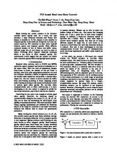
In order to make the communication system more convenient for the user, all the necessary commands to control the robot, such as moving the robot in 6 directions (x+ , x− , y + , y − , z + , z − ) or (de)activating the grabber (palm-to-fist or vice versa) are done by using a self developed GUI based application illustrated in Fig.3. As a first step, we track the user’s hand movement in a predefined volume covered by the MutiCam, followed by mapping its real world position into a virtual space which is represented by a cuboid of defined size and correlates with the MultiCam’s view frustum. Hand movement is visualized by placing a 3D hand-model in the according location within the cuboid. Depending on the hand’s distance from the cuboid’s center, a velocity vector is generated and wrapped into XML, along with some other state information and sent to the robot’s control unit which is in charge of unwrapping and sending the appropriate information to the robot itself. By placing the virtual hand in the cuboid’s center, the system can be put in a mode susceptible for special commands. For that matter, a rudimentary gesture classification algorithm has been implemented which is able to distinguish between a fist and
(Advance online publication: 20 November 2008)
IAENG International Journal of Computer Science, 35:4, IJCS_35_4_08 ______________________________________________________________________________________
3D Image Range Image (64x48 Pixels)
Modulation Image (64x48 Pixels)
Region Extraction (range filtering)
2D Image Color Image (640x480 Pixels)
Figure 3: Graphical User Interface (GUI) for hand based robot control, center: virtual space, top right: 2D color image, bottom right: 3D segmented image, top left: mode indicator, bottom left: detection result
2D Segmented Image
Overview of Hand Recognition and Tracking Algorithm
A general overview of the algorithm is shown in Fig.4. The inputs of the algorithm are the range, modulation and color images taken by the MultiCam. In the first step, the Volume of Interest (VOI) is extracted from the range image. VOI which has already been specified by the user is the volume where the user assumes to stand in and communicate with the robot from there. This volume which is specified in x,y-and z directions in the world coordinate system is projected to the 3D image. The pixels out of the volume in the range and modulation images are then filtered. This makes the detection of moving object in the cluttered background much simpler because the objects outside VOI do not appear in the image. In the next step, the filtered range and modulation data are used as the input features for a supervised clustering technique to segment the objects in the volume of interest. As 3D image has a low resolution, the segmentation is done very fast. The segmented range image is then mapped to the 2D color image. Due to the monocular setup of MultiCam, mapping from 3D range data to the corresponding 2D color data is trivial, and it does not need any extra calibration or registration techniques. This consequently makes the segmentation of 2D color image fast enough for our application. In the next step, the mapped color image is plugged into the supervised learning technique, AdaBoost to find the region of the hand in the image. The centroid of the found region is recorded as the position of the hand in that frame, and the posture of the hand (palm and fist) is classified using
Mapping 3D Segmented Image to 2D Color Image
Finding Hand Region using Ada-Boost Classification
Hand Found?
a palm. We use defined fist to palm transition sequences (e.g. a palm-fist-palm transition) in order to perform a robot reset, put the system in predefined modes and to (de)activate the magnetic grabber which in turn enables the whole system to handle ferric objects.
3
Unsupervised Clustering (3D Image Segmentation)
Yes
Posture Classification Recording Hand Position
No Next Frame
Figure 4: General overview of the algorithm a fast heuristic method.
3.1
Volume Extraction and Segmentation
Having the range information, VOI which is the working volume for the user can be specified as: V = xyz where xmin < x < xmax , ymin < y < ymax and zmin < z < zmax . The objects out of this volume are eliminated in the image. This simplifies the problem without involving in the complicated techniques for background modeling or image segmentation. VOI can be easily set by the user in each environment and therefore the application is quite independent of the background and it is applicable for any scenes. As it can be seen in Fig.5, after the extraction of the volume, the objects out of the volume disappear in the image. However, we still need to partition the pixels in VOI into meaningful objects using segmentation technique. In fact, segmentation is the first step of the image processing in the computer vision applications such as gesture recognition. It is the process of distinguishing the object of interest from the background as well as the surrounding non interesting objects. In other words, image segmentation aims at a better recognition of objects by grouping of the image pixels or finding the boundaries between the objects in the image. Gesture segmentation in this paper is treated as a clustering problem. Clustering is an unsupervised learning technique to identify the group of unlabeled data based on some similarity measures. Each group of unlabeled data so-called cluster corresponds to an image region while each data point is a feature vector which repre-
(Advance online publication: 20 November 2008)
IAENG International Journal of Computer Science, 35:4, IJCS_35_4_08 ______________________________________________________________________________________
Figure 6: Haar-Like features used in our work
Figure 5: Volume extraction and segmentation. top left: 2D color image, top right: 3D range image, bottom left: extracted 3D image, bottom right: segmented 2D image sents a pixel of the image. K-means is one of the simplest unsupervised learning algorithms that solve the well known clustering problem by partitioning the data set {x1 , x2 , ..., xN } into some number K of clusters. For each data point xn , a binary membership function is defined as: ½ 1 if xn assigned to cluster k rnk = 0 otherwise K-means aims at minimizing the objective function, given by [9]: N X K X J= rnk kxn − µk k2 (1) n=1 k=1
where kxn − µk k2 is the distance between the data point xn and the cluster center µk . In fact, the goal is to find the values for the {rnk } and the {µk } so as to minimize J. This is done through an iterative procedure in which each iteration involves two successive steps corresponding to successive optimization with respect to the rnk and the µk [9]. The main advantages of this algorithm are its simplicity and speed. The computational cost of K-means is O(KN ), which allows it to run on the large data sets in the real time. However, k-means is a data dependent algorithm. Although it can be proved that the procedure will always terminate, the algorithm does not achieve a global minimum. An example of segmentation is shown in Fig.5. K-Means provides fast results with high performance for our work. However, segmentation can still be improved by combining K-Means with Expectation Maximization which we discussed in [10].
3.2
Hand Detection and Tracking
After segmentation of the image, in the next step, the hand is detected and tracked in each frame to find it’s trajectory in order to control the robot. This is done by extracting the Haar-Like features and using them as the
input features for an adaptive boosting classifier called AdaBoost. Haar-like features which have been used successfully in face tracking and classification problems [11] encode some information about the object to be detected. These information is calculated by subtracting the sum of a black subregion of the feature from the sum of the white region of the feature. Fig.6 shows the features we have used in this work. The value of Haar-like feature is calculated as: X X f (x) = (pixel value) − (pixel value) (2) black
white
To detect the hand, the image is tracked by a subwindow containing a Haar-like feature. The presence of a Haar-like feature is determined by comparing f (x) with a threshold θ which is found in the training phase. If f (x) is above the threshold that feature is said to be present. ½ 1 if f (x) > θ ht (x) = 0 if f (x) < θ Determination of the presence or absence of all Haarlike features at every location of the image with different scales is computationally too expensive. Viola and Jones proposed an integral image technique which is extremely fast and can be used for real time applications [11]. To select the specific Haar features and set the threshold, the AdaBoost technique is used. AdaBoost combines many ”weak” classifiers to create one ”strong” classifier. H(x) =
T X
αt ht (x)
(3)
t=1
After a classifier is trained, it can be applied to a region of interest (of the same size as used during the training) in an input image. The classifier outputs a ”1” if the region is likely to show the object (i.e., hand), and ”0” otherwise. To search for the object in the whole image one can move the search window across the image and check every location using the classifier. The classifier is designed so that it can be easily ”resized” in order to be able to find the objects of interest at different sizes, which is more efficient than resizing the image itself [12]. However, in our work, as we have the range information
(Advance online publication: 20 November 2008)
IAENG International Journal of Computer Science, 35:4, IJCS_35_4_08 ______________________________________________________________________________________
from 3D image, the size of the hand (desired object) can be estimated and therefore we can set the initial size of search window without starting from a very small kernel size. This reduces the computational time for finding the hand in the image.
3.3
Posture Classification
After the hand has been detected using the AdaBoost classifier, in the next step the pose of the hand should be classified. In fact, we consider a binary classification problem to distinguish between palm and fist. Any change from palm to fist and vice versa are interpreted as a command for the robot. The technique we used is very simple, which originated from [3]. Having the distance of the hand to the camera from 3D range image, a circle is drawn at center of mass (derived from pixels with skin color in the found region) with a radius corresponding to the distance of the hand to the camera. In other word, the closer the hand to the camera, the bigger the circle. Then, the circle is tracked and the intersection of the circle with the hand is extracted as a binary function. The number of 1-to-0 transitions in binary function is counted and used as a feature to classify the hand. The mentioned technique which is described in details in Algorithm 1 can be seen in Fig.7. Algorithm 1 heuristic method for posture classification Assumption: The hand region D(x, y) has been found using AdaBoost. 1. Extract the all n pixels with the skin color in D and save it as E(x, y) data set. 2. Find Pthe center of mass PO of the hand in E : xi yi xO = n yO = n 3. Extract the distance value d of the center point O from 3D range image. 4. Draw a circle at the center point of O with the radius r corresponds to d. C = (x − xo )2 + (y − yo )2 = r2 5. Track the circle and construct a binary intersection function of the circle with the hand as follows: ½ 1 if x ∈ C f (n) = 0 if x ∈ /C 6. Count the number of 1-to-0 transitions and save it as a feature
4
Experimental Results
For the Hannover fair, a simple task had been defined to be performed by the visitors and to put the system’s performance under the test as follows: Commanding the robot to move in 6 directions using moving the hand with any kind of posture in the corresponding directions, picking up a metal object with the
1
1
0
0 0
Pixel
n
0
n
Figure 7: Hand classification using heuristic method. First row: posture class (palm, fist), Second row: binary intersection function of the palm and fist
Figure 8: Example of correctly detected images (True Positive)
magnet grabber using palm to fist gesture, moving the object using the motion of the hand and finally dropping it in the defined areas with palm to fist gesture. It turned out that the system handling has been quite intuitive, since different people have been able to operate the robot instantly. In terms of reliability the whole system worked flawlessly during the complete time exposed at the fair. For training of the classifier we took 1037 positive hand images from 7 people, and 1269 negative images from non-hand objects in our lab environment. Using OpenCv we trained our classifier with 20 stages and window size of 32x32. Although the classifier was trained under the lab conditions, it worked quite well under the extreme lighting conditions at the fair. In order to analyze the performance of the system, we recorded the results of hand detection from our GUI in the video format while different users were commanding the robot. Likewise, we moved the camera and took the videos from the environments where there is no-hand objects. These videos are labeled as ”Positive” and ”Nega-
(Advance online publication: 20 November 2008)
IAENG International Journal of Computer Science, 35:4, IJCS_35_4_08 ______________________________________________________________________________________
Table 1: Confusion table for hand detection system Hand Non-Hand Hand 2633 87 Non-Hand 224 2630 Sum 2857 2717
References [1] C. Wang and K. Wang, “Hand posture recognition using adaboost with sift for human robot interaction,” in International Conference on Advanced Robotics, 2007, 2007. [2] O. Rogalla, M. Ehrenmann, R. Zoellner, R. Becher, and R. Dillmann, “Using gesture and speech control for commanding a robot assistant,” in 11th IEEE International Workshop on Robot and Human Interactive Communication, 2002. [3] A. Malima, E. Ozgur, and M. Cetin, “A fast algorithm for vision-based hand gesture recognition for robot control,” in IEEE Conference on Signal Processing and Communications Applications, 2006. [4] T. Cerlinca, S. Pentiuc, and M. Cerlinca, “Hand posture recognition for human-robot interaction,” in Proceedings of the 2007 workshop on Multimodal interfaces in semantic interaction, 2007.
Figure 9: Example of wrongly detected images. First row: missed hand, Second row: misclassified
tive” data. Positive stands for hand and negative stands for non-hand objects. The data were acquired using a PC with dual core 2.4 GHz CPU. The exposure time for 3D sensor was set at 2ms while for 2D sensor it was about 10ms. Under these conditions, we had about 15 detected images (including all algorithms computational time) per second. The confusion matrix derived from these videos with 2857 hand images and 2717 non-hand images is shown in Table 1. As it can be seen from this table, the system has a Hit Rate of 0.921, False Positive Rate of 0.032 and the recognition accuracy of 94.4%.
5
Conclusion
This paper describes a new solution for hand based robot control using 2D/3D images. The multimodal 2D/3D images are taken by a novel monocular camera, MultiCam. These images are used as the input for a hand detection, classification and tracking system which is used as an interface for sending the commands to an industrial robot. The proposed solution has been implemented and tested under the real time conditions at the Hannover fair with the recognition accuracy of 94.4% at the video frame rate.
[5] Y. Fang, K. Wang, J. Cheng, and H. Lu, “A realtime hand gesture recognition method,” in 2007 IEEE International Conference on Multimedia and Expo, 2007. [6] S. Ghobadi, K. Hartmann, W. Weihs, C. Netramai, O. Loffeld, and H. Roth, “Detection and classification of moving objects-stereo or time-of-flight images,” in Computational Intelligence and Security. IEEE, 2006, pp. 11–16. [7] PMD, “Photoics pmd 3k-s 3d video sensor array with active sbi, www.pmdtec.com,” 2007. [8] O. Lottner, K. Hartmann, W. Weihs, and O. Loffeld, “Image registration and calibration aspects for a new 2d / 3d camera,” in EOS Conference on Frontiers in Electronic Imaging, 2007. [9] C. M. Bishop, Pattern Recognition and Machine Learning. Springer, 2006. [10] S. Ghobadi, O. Loepprich, K. Hartmann, and O. Loffeld, “Hand segmentation using 2d/3d images,” in IVCNZ 2007 Conference, Hamilton, New Zealand,, 2007. [11] P. Viola and M. Jones, “Rapid object detection using a boosted cascade of simple features,” in Conference on Computer vision and Pattern Recognition, 2001. [12] OpenCV, “The open computer vision library, intel.”
6
Acknowledgments
This work has been funded by German Research Foundation (DFG) under contract number LO 455/10-2 which is gratefully appreciated.
(Advance online publication: 20 November 2008)