ThP18.4
Proceeding of the 2004 American Control Conference Boston, Massachusetts June 30 - July 2, 2004
Real-time Multiple Parameter Estimation for Voltage Controlled Brushless DC Motor Actuators Ravindra Patankar IEEE member 1400 Townsend Drive, Houghton, MI 49931
[email protected]
Liangtao Zhu Michigan Technological University 1400 Townsend Drive, Houghton, MI 49931
[email protected]
Abstract − Brushless DC motors have been widely used as actuators in mechatronic systems. A non-dynamic motor inverse model, which neglects the electrical dynamics of the motor, is usually employed to achieve torque control of the motor. Variations of the motor parameters due to environmental factors, temperature, build variations, aging, etc. directly impart inaccuracies in the inverse motor model, and thus the dynamic performance of the system suffers. A multi-parameter estimation scheme is proposed in this paper. Improvements for the dynamic performance of the estimator are discussed. Comparison of closed loop simulations for voltage control BLDC motor in an electric power steering system confirms a lower bound of error of the estimated parameter and faster adaptation with the proposed improved estimation scheme.
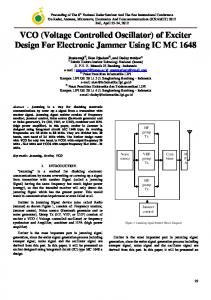
II. ADAPTIVE MULTI-PARAMETER ESTIMATION SCHEME Fig.1 shows a typical plant controlled in the closed loop. As shown in Fig. 1, an approximate inverse of the motor [5] neglecting the motor dynamics is used in the controller so that the fast motor dynamics are approximately cancelled by the controller to provide the expected torque output. Variations of the motor parameters will cause discrepancy between the motor inverse model used in the controller and the actual motor dynamics, therefore, the system in Fig. 1 has a motor-current based parameter estimation scheme.
I. INTRODUCTION Motors are the most commonly used actuators in mechatronic systems. Variations of the motor parameters such as coil resistance, coil inductance, torque constant directly impart inaccuracies in the control scheme based on the nominal values of parameters. The motor parameter variations generate output inaccuracies as a function of build, life, and temperature variations. To ensure adequate torque control and acceptable frequency domain performance, often it is desirable to compensate the control of the motor for variations in motor parameters including, but not limited to, motor resistance R and motor torque constant K e . Mir [1, 2] proposed on-line single parameter estimation for a brushless DC (BLDC) motor and verified the algorithm experimentally. Klienau et al [3] have proposed a current feedback error based single parameter estimation scheme for voltage controlled BLDC motors. However, when there exist errors in more than one parameter, performance of the singleparameter estimation schemes will deteriorate, and the accuracy of the control system will also suffer. Moseler [4] proposed a parameter estimation technique for a BLDC motor driven by a PWM inverter, where several parameters can be estimated by measuring the motor’s input and output signals. In this paper, a multi-parameter estimation algorithm is derived for the motor inverse model. Open loop simulation verified the effective-ness of the algorithm. Improvements for the algorithm are proposed for compensation of errors introduced by two assumptions in derivation of the estimation scheme. Closed-loop simulations presented for an electric power steering system plant demonstrate a lower bound on the error of the estimated parameter and a faster response time with the improved estimation algorithm.
0-7803-8335-4/04/$17.00 ©2004 AACC
Fig. 1. The schematic diagram of a mechatronic system with motor current based parameter estimation
2.1 Non-dynamic motor inverse model As a load control actuator of a mechatronic system, a threephase BLDC motor can be modeled by following equation[6, 7] di q L = − R i q − ω e L i d − K e ω m + V ⋅ cos δ , dt di (1) L d = − R i d + ω e L i q − V sin δ , dt Tout = K e i q . where, i q , i d − q and d axis currents mapped from the three phase currents, R − Motor coil resistance, K e − Torque and back EMF constant of the motor, L − Motor coil inductance, V − Input voltage to the motor, ω e − Angular velocity of electro-magnetic field,
ω m − Angular velocity of armature, ω e = ω m ⋅ N p 2 , N p is the number of magnetic poles, Tout − Motor torque output,
ωe L . R
δ − Phase advance δ = tan −1
1
3851
It is desired that the torque output of the motor tracks the desired torque ( Tcom ) from the controller. Tcom defines the desired q-axis motor current by the following equation T (2) i qcom = com . Ke Neglecting the electrical dynamics of the motor, i.e. di q di ≈ 0 , d ≈ 0 , the voltage V to be applied to the motor dt dt in order to get the desired torque Tcom at the output is obtained [3] from (1) as T T R 2 com + RK eω m + ω e 2 L2 com Ke Ke V = . (3) R cos δ + ω e L sin δ
,
(7e) (7f)
di q
= 0,
because of mechanical inertia, ∆ω