can be found successfully by the edge matching technique. 1 Introduction. The system we describe here provides part of an obstacle avoidance capability.
Stereo Vision-based Obstacle Detection for Partially Sighted People Stephen Se and Michael Brady Department of Engineering Science, University of Oxford, Oxford OX1 3PJ, U.K. {syss,jmb}@robots.ox.ac.uk Abstract. Obstacle avoidance is a major requirement for any technological aid aimed at helping partially sighted (TAPS) people to navigate safely. In this paper, a stereo vision-based algorithm (Ground Plane Obstacle Detection) is extended to detect small obstacles for TAPS using RANSAC dynamic recalibration and Kalman Filtering. Obstacle detection and false alarm are investigated probabilistically. Furthermore, a technique is developed to find objects by matching their edges with some heuristic criteria. Experiments show that obstacle edges are extracted much better with our dynamic recalibration approach and that objects can be found successfully by the edge matching technique.
1
Introduction
The system we describe here provides part of an obstacle avoidance capability for a TAPS. It will form a major part of the mobility function of a larger project, ASMONC (Autonomous System for Mobility, Orientation, Navigation and Communication) which aims to provide a full navigation and mobility capability for partially sighted people. A major requirement for the vision system is to detect small obstacles to help the user navigate safely along a path.
2
Ground Plane Obstacle Detection
Ground Plane Obstacle Detection (GPOD) using stereo disparity was first reported by Sandini et al. [3] and subsequently refined by Mayhew et al. [10] and by Li [7, 8]. GPOD is a feature-based stereo algorithm using a pair of cameras to determine features which do not lie on the ground plane. GPOD parameterises the ground plane using measurements of disparity and includes an initial calibration stage in which the ground plane parameters are extracted. GPOD works in image coordinates, and compares the disparity values in a new image pair with the expected ground plane disparity to detect differences (hence obstacles). Vertical edges are detected using a Sobel detector, and stereo matching uses the PMF algorithm [13, 14]. Images of the ground with line features but no obstacles are used to initialise the ground plane estimate. The ground plane disparity d varies linearly with cyclopean image plane coordinates (u, v) [8], that is d = au + bv + c where (a, b, c) are the ground plane parameters.
(1)
3
Probability and False Alarms
In purely geometric terms, we can easily derive how many pixels are subtended by an obstacle, however, noise makes obstacle detection a stochastic process and geometry alone does not capture the stochastic element. Therefore, reliability is inevitably expressed probabilistically [9].
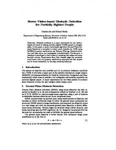
Camera
Y H θ
A ∆Y S
θ
B
Fig. 1. The camera geometry showing the various parameters.
Disparity is given by d = fYI , where f is related to the camera intrinsic parameters, I is the interocular distance, and Y is the distance to the object or ground [5]. Referring to Figure 1, the quantity used in GPOD for checking obstacles is the difference between the measured disparity at A and the predicted disparity at B, which is # " � � ∆Y fI fI S fI fI Y ∆d = = − = (2) Y Y + ∆Y Y 1 + ∆Y Y H Y The probability of detecting an obstacle of size S is the probability of its disparity difference being larger than the threshold. Assuming that the disparity difference is normally distributed, from Equation 2, we have Z ∞ f IS ∆d− 1 − 12 ( σ Y H )2 ∆d √ e P (∆d > threshold|S) = d(∆d) (3) 2πσ∆d threshold We can illustrate this by analysing the case in which we want to detect an object of height 10cm (e.g. a small step, sufficiently high to inconvenience a partially sighted person) at a distance of 5m. With our known camera configuration and 2 parameters, this corresponds to a disparity difference of 1.7. In Equation 3, σ∆d is the variance of the disparity difference given by 2 σ∆d = σd2measured + σd2expected
where σd2measured = 1 is assumed and σd2expected is given by the ground plane parameters uncertainty analysis [16] assuming the image coordinates variances are unity.
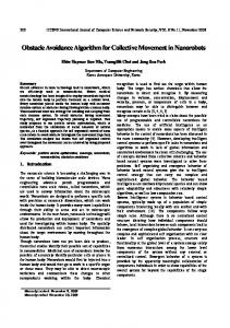
A vertical edge string of length m is regarded as an obstacle if at least one pixel of the edge string is detected as an obstacle. Therefore, if pi is the probability obtained in Equation 3 for the ithQpixel, then assuming independence, m the probability of obstacle detection is 1 − i=1 (1 − pi ). Figure 2 shows the probability of obstacle detection for different obstacle sizes at various distances. We see that with our current configuration, to obtain 90% detection rate, the minimum obstacle size increases from 6cm to 11cm as the distance increases from 2.5m to 5m.
1 0.9
2.5m 3m
0.8
3.5m
4m 4.5m 5m
Probability of Detection
0.7 0.6 0.5 0.4 0.3 0.2 0.1 0 0
2
4
6
8 10 12 Obstacle Size (cm)
14
16
18
20
Fig. 2. Obstacle detection probability at various distances (threshold=1.7).
False alarm probability is the likelihood that an obstacle is detected when nothing is actually there: Z ∞ (∆d−LSF E)2 − 1 2σ 2 ∆d √ d(∆d) P (F alse Alarm) = e 2πσ∆d threshold where LSF E is the least-squares fitting error, i.e. d(u,v) − (au + bv + c), in which d(u,v) is the measured disparity for a ground plane point (u, v). Figure 3(a) shows the false alarm rate for a typical obstacle-free scene when threshold is 1.7. It indicates quite a high false alarm rate. However, we can discard any single-pixel obstacles detected and not regard them as false alarms, since it is highly likely that they are due to noise. Let pixel (i − 1), pixel i and pixel (i + 1) be three consecutive pixels on a vertical edge, and let Pi−1 be the probability of a false alarm for pixel (i − 1), Pi that for pixel i, and Pi+1 that for pixel (i + 1). Then, the false alarm probability (excluding single-pixel obstacles) is given by Pi − (1 − Pi−1 )Pi (1 − Pi+1 ). Figure 3(b) shows the false alarm rate in this case which is reduced substantially compared to Figure 3(a), as the chance of two consecutive points being affected by noise in the same way is much lower. A real obstacle can reasonably be expected to occupy at least a few contiguous pixels, so this simple heuristic does not affect obstacle detection much.
Probability of False Alarms (excluding single pixel) against Distance 0.5
0.45
0.45
0.4
0.4
0.35
0.35
Probability of False Alarms
Probability of False Alarms
Probability of False Alarms against Distance 0.5
0.3 0.25 0.2 0.15
0.3 0.25 0.2 0.15
0.1
0.1
0.05
0.05
0 2
2.5
3
3.5
4 4.5 Distance (m)
5
5.5
(a)
6
6.5
0 2
2.5
3
3.5
4 4.5 Distance (m)
5
5.5
6
6.5
(b)
Fig. 3. False alarm probability for real ground plane data. (a) With threshold being 1.7. (b) With exclusion of single-pixel obstacles and threshold being 1.7.
4
RANSAC Dynamic Ground Plane Recalibration
For wheeled mobile robots moving over flat ground, there is no relative change in position of the ground plane from the cameras, hence the cyclopean groundplane disparity function is fixed. However, cameras attached to the shoulders of a partially sighted person in a TAPS move up and down while he/she is walking around. The cameras move with six degrees of freedom. Therefore, a one-time, fixed ground plane calibration cannot be used to detect small obstacles. 4.1
Dynamic Ground Plane Recalibration (DGPR)
We propose dynamic recalibration of the ground plane to prevent human movement affecting obstacle detection and to obtain a better estimate of the ground plane for slopes, hills or non-flat ground. DGPR [15, 12] recalibrates the ground plane parameters at each step. Iteratively, it uses step k’s ground plane parameters for obstacle detection, partitions the features found into ground plane features and obstacle features. The ground plane features and the estimated camera movement between steps are then used to obtain step k+1’s ground plane parameters. 4.2
Kalman Filter Tracking
In a multiple target tracking system, we confront the data association problem, which addresses how to associate predictions of target positions with actual measurements. The Mahalanobis distance [17] quantifies the likelihood of a measurement originating from a specific geometric feature. The nearest-neighbour approach uses this distance metric to associate the measurements to their closest geometric features. It may perform badly as the closest measurements are not always correct [2]. Nevertheless, it is both computationally and conceptually simple, and is employed in our current work.
We use the Kalman Filter [1] to track ground plane features as well as obstacle features. Their positions can be determined more accurately and, with suitable track initiation and termination techniques, we can deal with situations such as new features coming into the scene, existing features leaving the scene and temporary occlusion. In addition to tracking ground plane features, we use a further Kalman Filter to track the ground plane parameters in order to better estimate them. 4.3
RANSAC Ground Plane Fitting
In DGPR, the six d.o.f. camera motion parameters are required for the prediction of ground plane parameters for obstacle detection in the next frame. However, they are difficult to obtain accurately [11], therefore, we use RANSAC [4] for ground plane fitting in each frame. RANSAC takes all the image features (provided that there are sufficiently many ground plane features, and not all obstacle features lie on the same plane), fits the ground plane features and discards the obstacle features as outliers. A sequence of stereo images of a real outdoor scene was captured at 128x128 resolution. The environment is a tiled pavement with various obstacles. There was some camera motion between the images with translations up to 20cm and rotations up to 5 degrees, which cover the extreme case for human movement [6]. Figure 4(a) shows an image of the sequence where the white rectangle indicates the window of interest. Results from GPOD and RANSAC-DGPR are shown in Figures 4(b) and 4(c) respectively, where detected obstacle edges are marked. It can be seen that obstacles are missed by GPOD but are detected by RANSAC-DGPR, showing that using only the initial ground plane parameters is insufficient to detect obstacles in the presence of camera motion, and that the RANSAC-DGPR approach gives promising results. Detected obstacles in the scene include a 10cm-high brick at 1.5m and a 15cm-high box at 3m.
5
Objects
So far, only obstacle edges have been detected, as edges are sometimes weak, we cannot tell which pairs of vertical edges correspond to the sides of an object. This makes it difficult to advise the partially sighted person how to avoid the obstacles. An edge matching technique is developed using notions similar to disparity constraints, intensity correlations and mutual admiration in stereo. 5.1
The Algorithm
Among the edges in the candidate edge list, for each pair of edges i and j, compute a ‘score’ indicating the likelihood of them being the two sides of an object (see the next section). For edge i, find its partner by choosing an edge which gives a lowest score among all the other edges. If there exist edges i and j (i 6= j) such that edge i chooses edge j and edge j chooses edge i (mutual admiration), then edges i and j are declared as a pair and removed from the candidate edge list.
(a)
(b)
(c)
(d)
Fig. 4. Obstacle detection. (a) The original image. (b) Result from GPOD. (c) Result from RANSAC-DGPR. (d) Edge matching on RANSAC-DGPR result.
Any score needs to be below a threshold, otherwise, the pair is not declared. This is to allow cases where there does not exist a match for a certain edge. Repeat until all possible pairs are picked out. 5.2
Scoring
For each prospective edge pair, we compute a score to determine how likely it is that they are the two sides of a single object. This score consists of three factors: disparity, position and intensity. Normally, the two sides of an object should be at about the same distance from the camera, therefore they should have similar disparities. Let the average disparity of the two edges be d1 and d2 respectively, then we have Df actor = k1 |d1 − d2|. There are three components to the position factor: u-direction, v-direction and length. Let u1 and u2 be the horizontal coordinates of the two edges under consideration. We would like to eliminate the case of them being too close, in particular, to avoid u1 = u2 as they could not be a pair in that case: we have a term inversely proportional to |u1 − u2|. However, by itself this would bias towards picking two edges as far away as possible which is contrary to the usual situation. k2 Therefore, we propose P uf actor = |u1−u2| + k3 |u1 − u2|. The midpoint of the two edges forming a pair should be at a similar distance. Let v1 and v2 be the vertical coordinates of the midpoint of the two edges, we propose P vf actor = k4 |v1 − v2|. The two edges forming a pair should be of similar length. Let l1 and l2 be the lengths of the two edges, then we propose P lf actor = k5 |l1 − l2|.
Similarly, there are two components to the intensity factor. If two edges are the sides of an object, the intensity to the left of one edge (Il1 ) is in many cases similar to that on the right of the other (Ir2 ); the intensity to the right of the one edge (Ir1 ) should also be similar to the intensity to the left of the other edge (Il2 ). The same applies to both left and right images, indicated by superscribing with l and r respectively. We propose l l l l r r r r I1f actor = k6 (|Il1 − Ir2 | + |Ir1 − Il2 | + |Il1 − Ir2 | + |Ir1 − Il2 |)
Moreover, we also need to check the intensity of a patch between the prospective pair against the average background intensity. Let G be the average intensity of the whole image, assuming most of it is ground region with relatively little obstacle clutter, then G is close to ground region intensity. We can use a 3x3 patch between the two edges and find the average intensity Iav to compare against G. k7 For this reason, we propose I2f actor = |G−I . av | Finally, the factors are summed to give a score for the prospective pair under consideration. The constants ki s appearing in the factors are partly experimental and are individually weighed according to their importance and stability under noise. For example, since the Df actor is important and stable to noise, it is given a larger weight. On the other hand, we find that the image coordinates and pixel length are susceptible to noise, hence have smaller weights. We also need to set the threshold t above which a match is not declared. 5.3 Results Sensitivity analysis shows that the following chosen parameters (k1 = 100, k2 = 500, k3 = 10, k4 = 10, k5 = 10, k6 = 1, k7 = 5000, t = 1000) give stable results. Applying this to the result from Figure 4(c), we obtain Figure 4(d). Each object block, whose two sides are paired, is indicated. The result shows that the score function does provide sufficient discriminating power for pairs to be matched in scenes without too much clutter. We can locate the objects now which will enable effective navigation for the partially sighted.
6
Conclusions
We have extended the GPOD algorithm developed originally for mobile robots to include dynamic recalibration of the ground plane, Kalman Filter tracking of features and RANSAC ground plane fitting in successive images. The experimental results from our implementation show that RANSAC-DGPR can detect small obstacles much better than GPOD in the presence of camera motion. Moreover, we have investigated obstacle detection and false alarm in probabilistic terms and demonstrated that objects can be found from matching their edges with criteria based on heuristics. There are, however, some assumptions made which require further investigation and justification, such as the variances of the image coordinates. The current DGPR implementation takes 1.5 seconds on the average to process a pair of 128x128 images on an Ultra-Sparc machine. So before it can be actually used by the partially sighted, we will need to achieve at least near real-time speed by parallelisation and other optimisations.
Acknowledgements We thank Fuxing Li for many useful discussions about GPOD, and David Lee, Nick Molton & Penny Probert for collaborations on ASMONC. JMB thanks the EPSRC for support during his Senior Fellowship. SS thanks EPSRC for his Graduate Studentship support.
References 1. Y. Bar-Shalom and T.E. Fortmann. Tracking and data association. Academic Press, Boston, London, 1988. 2. I.J. Cox. A review of statistical data association techniques for motion correspondence. International Journal of Computer Vision, 10(1):53–66, February 1993. 3. F. Ferrari, E. Grosso, G. Sandini, and M. Magrassi. A stereo vision system for real time obstacle avoidance in unknown environment. In Proceedings of IEEE International Workshop on Intelligent Robots and Systems IROS ’90, pages 703– 708, 1990. 4. M.A. Fischler and R.C. Bolles. Random sample consensus: a paradigm for model fitting with application to image analysis and automated cartography. Commun. Assoc. Comp. Mach., 24:381–395, 1981. 5. B.K.P. Horn. Robot Vision. The MIT Press, 1986. 6. D. Lee. The movement of sensors carried on the trunk of a walking person. Oxford University, January 1996. 7. F. Li. Visual control of AGV obstacle avoidance. DPhil First Year Report, Department of Engineering Science, University of Oxford, 1994. 8. F. Li, J.M. Brady, I. Reid, and H. Hu. Parallel image processing for object tracking using disparity information. In Second Asian Conference on Computer Vision ACCV ’95, pages 762–766, Singapore, December 1995. 9. L. Matthies and P. Grandjean. Stochastic performance modeling and evaluation of obstacle detectability with imaging range sensors. IEEE Trans. on Robotics and Automation, 10(6):783–792, 1994. 10. J.E.W. Mayhew, Y. Zheng, and S. Cornell. The adaptive control of a four-degreesof-freedom stereo camera head. In H.B. Barlow, J.P. Frisby, A. Horridge, and M.A. Jeeves, editors, Natural and Artificial Low-level Seeing Systems, pages 63–74. The Royal Society, London, 1992. 11. N. Molton. Egomotion recovery from stereo. DPhil First Year Report, Department of Engineering Science, University of Oxford, 1996. 12. N. Molton, S. Se, J.M. Brady, D. Lee, and P. Probert. A stereo vision-based aid for the visually impaired. Image and Vision Computing, 1997. to appear. 13. S.B. Pollard, J.E.W. Mayhew, and J.P. Frisby. Implementation details of the pmf stereo algorithm. In J.E.W. Mayhew and J.P. Frisby, editors, 3D Model Recognition From Stereoscopic Cues, pages 33–39. MIT, 1991. 14. S.B. Pollard, J. Porrill, J.E.W. Mayhew, and J.P. Frisby. Disparity gradient, lipschitz continuity, and computing binouclar correspondences. In J.E.W. Mayhew and J.P. Frisby, editors, 3D Model Recognition From Stereoscopic Cues, pages 25– 32. MIT, 1991. 15. S. Se. Visual aids for the blind. DPhil First Year Report, Department of Engineering Science, University of Oxford, 1996. 16. S. Se and M. Brady. Vision-based detection of kerbs and steps. In Eighth British Machine Vision Conference BMVC ’97, pages 410–419, September 1997. 17. Z. Zhang and O. Faugeras. 3D Dynamic Scene Analysis. Springer-Verlag, 1992.