Real Time Performance Modeling of (3G) UMTS System R. Badrinath*a , A. Mitrab , N. Sinhaa , N. Mukherjee**a a
Department of Computer Science and Engineering, b Department of Mathematics and Computing Indian Institute of Technology , Kharagpur – 721302
ABSTRACT Universal Mobile Telecommunications System (UMTS) wireless technology is a proposed standardization as a part of 3GPP solutions to satisfy IMT-2000 requirements. It is based on wideband CDMA technology. It will provide full coverage and mobility for 144 Kb/s, preferably 384 Kb/s and limited coverage and mobility for 2 Mb/s. It proposes high spectrum efficiency compared to existing systems, handling of different QOS profiles and high flexibility to introduce new service. In this paper, we present our work on modeling of the access stratum (AS) on the User Equipment/Mobile Termination (UE/MT) side of the radio (Uu) interface in accordance with 3GPP UMTS standards. The AS has the following sub-layers: Medium Access Control/Radio Link Control (MAC/RLC), Broadcast Multicast Control (BMC), Packet Data Convergence Protocol (PDCP) and Radio Resource Control (RRC). We have assumed the number of transport channels interfacing the AS MAC sub layer and the physical layer to be eight. The data rates have been assumed to be 384 Kb/s per transport channel both in uplink and downlink Processing in each sub-layer with corresponding delays and interaction between adjacent sub-layers having timing restrictions or rate restrictions have been analyzed. Interaction of the upper sub-layers with the non-access stratum (NAS) and interaction between peer AS sub-layers in the UE and the UTRAN have also been incorporated. A real time priority based scheduler process has been specified to honor the time restrictions e.g. the Transmission Time Intervals (TTI) of the channels. The system has been simulated on Virtual Silicon, a C based SDL tool and evaluated on CR16C architecture family using CR16C debugger, both developed by National Semi conductor Corp., U.S.A.
Keywords: Universal Mobile Telecommunications System (UMTS), Access Stratum (AS) , MAC/RLC, RRC, UE, UTRAN, TTI, Virtual Silicon, CR16C
1. INTRODUCTION Emerging requirements for higher rate data services and better spectrum efficiency are the main drivers identified for the necessity of third-generation mobile radio systems. The International telecommunications Union has been developing third-generation network systems under International Mobile Telecommunications (IMT-2000) previously termed Future Public Land Mobile Telephone System (FPLMTS)2. In Europe, third generation networks are being developed as Universal Mobile telecommunications System (UMTS). UMTS1,3,4 standardization started in 1990 under ETSI . the European Telecommunications Standard Institute.
*
[email protected] ;phone +91 3222 83460 ;fax +91 3222 78985 ;http://144.16.202.161:8081/~badri ;Deptt. Of Computer Science and Engineering, IIT Kharagpur – 721302; **
[email protected]; phone (617)-2530384;http://www.media.mit.edu/~niloy; MIT Media Laboratory, 20 Ames Street, Cambridge MA 02139
The main objectives for the UMTS air interface may be summarized as: •
Mobility specification of 144 Kbps to 384 Kbps in a full coverage purpose
•
Limited coverage and mobility for 2 Mbps
•
Spectrum efficiency and bandwidth improvement compared to existing systems
•
Quality of service management to introduce and support multi media applications
The target bit rates have been fixed as per the Integrated Services Digital Network (ISDN). The air interface has been specified to be wideband Code Division Multiple Access (wideband CDMA). The technology push from Japan, Europe and United States of America has made it very well established that a global world wide system of mobile networks which should support both circuit switched and packet switched backbones, a huge range of multimedia applications, huge data rate and quality of service assurance will be possible in the next 5 to 6 years using Wideband CDMA as the multiple access scheme. In this paper, we describe our work in simulating UMTS architecture as proposed by 3GPP standardization. The project has been undertaken in collaboration with National Semiconductor Corp. U.S.A. We have concentrated on Access Stratum (AS) , a subset of UMTS architecture on the User Equipment (UE) domain relevant to the radio (Uu ) interface between a Mobile Terminal (MT) and a terrestrial Radio Network Controller (UTRAN) . The Access Stratum (AS) is interfaces the Non Access Stratum (NAS) responsible for higher layer non-radio applications and the Physical Layer responsible for data transfer using wideband Code Division Multiple Access Scheme. The sub layer processes in MAC , RLC , RRC and other layers constituting AS have been identified . Delay models have been constructed for these processes honoring time and rate restrictions pertaining to them. Using Virtual Silicon, a C based SDL tool from National Semiconductor Corp. U.S.A., finite state machines corresponding to the various protocol layers were built. The delay models were fed into these machines. To honor real time constraints these finite state machines were made to carry out inter process communication through a scheduler. The behavior of the system has been studied under different scheduling schemes to determine the best possible scheduling policy. As far as the architecture layers are concerned, we have dealt with the Quality of Service (QoS) control of MAC , its communication with the RRC regarding traffic measurements and RLC regarding transmission of higher layer Packet Data Units (PDUs)5. RLC mainly looks at flow control, error control and status report to RRC ensuring a correct protocol for transmission/reception of data units6. RRC7 controls various traffic parameters e.g. Quality of Service parameters and Radio Bearer parameters on decision with its peer in the UTRAN. Hence to summarize, our system needed two different approaches to be merged. •
Identification of flow layer by layer and model the flow as composition of Finite State Machines
•
Identification of task blocks in the above layers and replacement by delay models on a suitable architecture
The rest of the paper is organized as follows. . Section 2 gives a brief introduction to the components of the UMTS Access Stratum. We talk about the design issues in MAC, RLC and RRC, which honor their real time behavior in Section 3. In Section 4 we discuss our simulation model. The behavior of the first pass system has been studied in Section 5. Finally we conclude by presenting a summary over the system behavior and some suggestions needed for future work in Section 6.
2. UMTS TECHNOLOGY The UMTS Technology proposes a basic architectural split between the user equipment and the infrastructure. This results in two domains: the User Equipment Domain and the Infrastructure Domain1.User equipment refers to equipment used by the user to access UMTS services. The user equipment has a radio interface to the infrastructure. The infrastructure consists of the physical nodes that perform the various functions required to terminate the radio interface and to support the telecommunication service requirements of the users. The reference point between the user equipment domain and infrastructure domain is termed as the Uu reference point (UMTS radio interface). This architectural model can be further specified in terms of Access Stratum entities, which provide service to the higher layers that do not communicate end-end with the Infrastructure edge node. 2.1 OVERALL PROTOCOL STRUCTURE
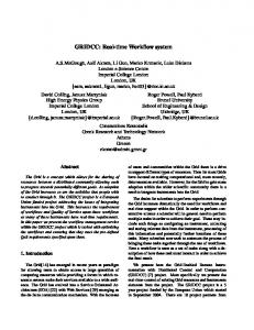
The radio interface4 is layered into three protocol layers: the physical layer (L1) , the data link layer (L2) and the network layer (L3) . Layer 2 is divided into the following layers: Medium Access Control (MAC), Radio Link Control (RLC) , Packet Data Convergence Protocol (PDCP) and Broadcast/Multicast Control (BMC). Layer 3 overlaps with the radio interface as well as the Non Access Stratum (NAS). The Radio Resource Control (RRC) sub layer constitutes the split of Layer 3 in the radio interface. Figure 1 shows the components of UMTS architecture
Figure 1: The Radio Interface Architecture
The SAP between MAC and the physical layer provides the transport channels (ref). The SAP s between RLC and the MAC sub layer provide the logical channels 4. The number of simultaneous transport channels has been assumed to be eight. Also shown in the figure are connections between RRC and MAC as well as RRC and L1 providing local inter-layer control services. An equivalent control interface exists between RRC and the RLC sub layer, between RRC and the PDCP sub layer and between RRC and BMC sub layer. These interfaces allow the RRC to
control the configuration of the lower layers. For this purpose separate Control SAP s are defined between RRC and each lower layer (PDCP, RLC, MAC, and L1). The RLC sub layer provides ARQ functionality closely coupled with the radio transmission technique used.
2.2 MEDIUM ACCESS CONTROL SUBLAYER The Medium Access Sub layer is constructed from the following MAC entities5 •
MAC-b : This entity handles the Broadcast Channel (BCH). There is one MAC-b entity in each UE
•
MAC-c/sh: This entity handles the Paging Channel (PCH), the Forward Access Channel (FACH), the Random Access Channel (RACH). There is one MAC-c/sh entity in each UE and one in the UTRAN for each cell.
•
MAC-d : This entity is responsible for handling of dedicated logical channels and transport channels. There is one MAC-d entity in each UE and one MAC-d entity in the UTRAN for each UE.
2.3 RADIO LINK CONTROL SUBLAYER The Radio Access Sublayer6 is constructed from the following entities: •
Transparent Mode entity: The entity receives segmented data units (SDUs) from higher layers through the TrSAP. It converts the SDUs to RLC packet data units (PDUs) by segmenting or concatenating several SDUs and transmits them to the relevant logical channel as governed by Radio Resource Control Layer (RRC). Similar action is taken in the downlink
•
Unacknowledged Mode entity: The entity receives segmented data units from higher layers through the UMSAP. The entity performs ciphering/deciphering of SDUs as well as addition of RLC overhead.
•
Acknowledged Mode entity: The entity deals with o o o o
Error control Flow control In sequence delivery of packet data units Buffer and retransmission management
2.4 RADIO RESOURCE CONTROL LAYER We have dealt with parts of Radio Resource Control (RRC)7 controlling the MAC and the RLC sub layers. The RRC entity designed mainly covers o o o o o
Configuration of the MAC, RLC Request for traffic volume measurements from RRC Controlling Transmission Time Interval (TTI) of transport channels Controlling Packet data size to be sent on transport channels Governing data specific parameters in RLC and MAC
3. DESIGN ISSUES IN UMTS In this section we discuss some issues that governed the design and performance of our simulation model. Among the various sub layer procedures we discuss some of these, which deal with the real time constraints of the model. We also discuss the protocol layers as Finite State machines and identify properties related to them. 3.1 HANDLING OF TRANSMISSION TIME INTERVAL OF TRANSPORT CHANNELS Transmission Time Interval (TTI)4 is the amount of time required by the Physical Layer to send a block of packets, Transport Block Set for each of the transport channels. The number of packets in a Transport Block as well as the size of a Transport Block is governed by the peer-peer RRC connection. In our system we have eight transport channels each with a TTI of multiples of 10ms. The dedicated transport channels were assigned less TTI to maintain a high data rate on them. We have dealt with Transmission Time Interval as the time interval on each Transport Channel for which we can send down Packet Data Units (PDUs) from MAC to Physical Layer. Therefore, we maintain eight timers , one for each of the transport channels ,synchronized with one another. We maintain a Global Timer queue which we discuss in the next section which honor the TTI restrictions. 3.2 TRAFFIC VOLUME MEASUREMENT IN MAC RRC requests traffic volume measurements from MAC to determine the flow of data into the respective transport channels. Traffic volume monitoring occurs in MAC on the request of RRC. MAC receives RLC Packet Data Units together with RLC transmission buffer information. Every TTI, MAC compares the amount of data on each Transport Channel with the thresholds set by RRC. If the value is out of range , MAC reports the volume status to RRC. RRC , on basis of this report determines bearer reconfiguration. There are two modes on which MAC reports traffic status to RRC. It may do it as an event triggered or periodically as governed by RRC. 3.3 QUALITY OF SERVICE CONTROL IN MAC The Quality of Service parameters are governed in the Transport Format Set4 maintained by RRC. The Transport Format has both semi static and dynamic parameters. Dynamic parameters include the PDU size and the Transport Block Set size and semi static parameters include the Transmission Time Interval values. The RRC sends down a Transport Format set to the MAC when it requests for reconfiguration of the transport channels. The Transport Format selection process depends on the logical channel priority . Logical channel priorities are determined by RRC and signaled down to MAC. We have dealt with absolute logical channel priorities , i.e. , the Transport Format is chosen in a way that a higher priority logical channel is never blocked. For contention based Access Channels such as Random Access Channel (RACH) there are opportunities to partition Transport Blocks or RLC PDUs to several Access classes. Each Access Class is characterized by its own quality management parameters to determine priority for RACH usage. We have used the ASC selection scheme as proposed by 3GPP standards 4 3.4 MAC AS A FINITE STATE MACHINE An important issue in our design was to generalize protocol states to finite state machines. These finite state machines are such that they wait on a state for a signal to initiate the state transition. We will discuss these issues in the next section. We came up with Finite State machine model for MAC. The model is shown in figure 2. The CMAC-CONFIG and the CMAC-MEASURE signals shown in the figure initiate state transitions in the model from null state to either the “DATA READY” or the “MEASURE” state. The “data ready” state does the necessary transmission functions from lower/higher layers and goes to the “measurement” state if RRC configures a periodic measurement request for the MAC. The MAC can be reconfigured as per RRC request. MAC either remains in either of the two states when the system is totally powered on.
Figure 2 MAC as a finite state machine 3.5 TRANSMISSION MANAGEMENT IN RLC We like to discuss some issues related to transmission management in RLC. RLC uses both PIGGYBACKING 6 and non-PIGGYBACKING modes of acknowledged data transfer. RLC uses a Poll Mechanism to request for status reports from its peer. There are sets of timers which govern the necessary time constraints for these mechanisms. The values of these timers are specified by RRC. Some of these timers operate periodically while others are non-periodic. On elapse of these timers, poll is sent from transmitting RLC to its peer . Status reports from the peer are transmitted periodically as well as non-periodically on basis of the related timers on the peer side. Detailed descriptions of these timers are available in 6. 3.6 RLC AS A FINITE STATE MACHINE As in the case of MAC we considered Finite State Machines for RLC. The figures show the model of transparent mode of transfer. The CRLC-CONFIG-Req configures, reconfigures or releases bearer connections. The Transparent Mode works in a single “data ready” mode. The Acknowledged mode works in normal as well as “Local Suspend” mode where it does not send packets with sequence numbers greater than a certain threshold. The Acknowledged mode can also work in “Reset Pending” mode when connection is reset due to protocol errors and reconfigured after receiving a RESET ACK packet from the peer.
Figure 3: RLC as finite state machine
4. SIMULATION MODEL As we mentioned in Section 1 our system followed two basic approaches: Simulation of the flow across each of the layers and replacement of each sub layer process by a delay model. For the first step we used Virtual Silicon tool and for the second step we used CR16C debugger. The development tool as well as the debugger was provided by National Semiconductor Corp. U.S.A. We will discuss our system details iteratively in the following sub sections. 4.1. THE SYSTEM –BLOCKS OF PROCESSSES The C-based specification language used in Virtual Silicon known as MAGIC-C supports the grouping of objects in larger units. This introduction of hierarchy allows powerful abstraction and hiding of low-level details. The Access Stratum Block is a container for Finite State Machines (FSMs) as captured in the concept of processes. These processes include MAC , RLC , RRC , the higher application layer and the lowest physical layer. There is no specific behavior associated with a Block, its behavior is the combination of the behavior of the underlying processes. 4.2 BEHAVIOR OF STATES AND TRANSITIONS-OUR SCHEDULER PROCESS Initialization places all the processes into a start construct. At that point each process executes a transition to a State executing an action specified as a Task on the transition. Inter process communication is possible throudh a range of Signal variables. Processes receive (and keeps) signals in a (implicit) queue. Let us discuss our scheduler process based on Virtual Silicon environment properties. The scheduler goes to an “idle” state after getting initialized. The scheduler waits on this state for the “need_resched” signal to wake up from “idle” state. The “need_resched” signal is sent to the Scheduler by our Layer processes as and when needed, which we discuss in Section 4. The scheduler maintains two queues : o Priority based Global Timer Queue – List of all timers that are active at the current moment. The Scheduler checks whether any of these timers have elapsed. On the basis of priority it throws out the respective Timer Wakeup signal to the processes waiting on these Timers o
Global Signal Queue – List of all signals other than timers. This queue has lower priority than the Global Timer Queue. On basis of the signal priority , the Scheduler throws out respective signals
The Scheduler comes again to the “idle” state waiting on the “need_resched” signal.
4.3 HIGHER AND LOWER LAYERS The Higher and Lower Layers have been designed as packet generators. These processes are woken up by the Internal simulation timer or by Wakeup signals thrown out by the Scheduler process. These processes generate packets and signal the Scheduler to wake up at periods. We assume negative exponential distribution for arrival of packets from Higher Layer and Constant Bit Rate (CBR) for packets arriving from Lower layer. 4.4 TIMERS AND CLOCKS As seen from previous sections , we have a set of timers in MAC honoring the Transmission Time Intervals of the Transport channels. We also have a set of timers in RLC which honor Flow Control , Error Control and transmission Management. There are two kinds of Wakeups that we have supported in our system. One is the internal simulator wakeup which gives control to the Higher and Lower layer processes when the Scheduler has no signal to serve. The other Wakeup type is given when the Scheduler examines the Global Timer Queue to release timer wakeups when elapsed. We have got our own system clock running in microseconds which gets incremented as per the requirements of the delay models 4.5 INTER PROCESS COMMUNICATION As we said in Section 1, we have the Scheduler process as the main arbiter of jobs. In Virtual Silicon , interrupts take control at the States. So a transition from one state to another is atomic in Virtual Silicon. Between states the flow can not be interrupted. Hence to give the essence of pre emption we injected the scope of interruption whenever a process completes a transition and enters a state. Therefore we release “need_resched” signal to wake up the Scheduler whenever the system enters a state completing a transition. If a transition gives out signals for other processes , these signals are saved in the Global Signal queue. The control is given to the scheduler. Thus the scheduler is honored as being the main controller of the system. Processes communicate between themselves through the Scheduler. 4.6 THE LAYER PROCESSES-MAC , RLC AND RRC The MAC RLC and the RRC processes have been visualized as combinations of FSMs analogous to the protocol states diagrams in Section 3. 4.7 THE CR16C DEBUGGER The CR16C debugger has been used to examine the delay models of various sub layer processes. The debugger emulates the family of CR16C architecture brought up by National Semiconductor Corp. U.S.A. For our purpose we chose the clock speed to be 100 – 200 Mega Hertz. We list in figure 4 the number of clock cycles taken for some of the sub layer procedures
RELEVANT PROCEDURES
NO. OF CYCLES
Traffic Volume Measurement in MAC
756
Transport Format Selection in MAC
205
Buffer and Transmission Management in RLC Selection Protocol Data Unit Overheads in RLC
897 572
Figure 4: List of cycles taken by time-constrained procedures
5. SIMULATION RESULTS In this section we discuss some issues related to execution of the system. We have already listed the delay models in the previous section. One of the time consuming models were the Ciphering procedure. The other procedures were time-optimal as per our need. We discuss parts of Ciphering procedure, which we simulated as hardware in order to decrease its delay. We found out the scheduler algorithm to be a main issue to maintain the time requirements of the system. In our first pass system we came up with the First Come First Serve (FCFS) algorithm. While running the system we found that the algorithm becomes both time and space inefficient . This gets worsened when the RLC keeps on sending signals to the Scheduler at its Local Suspend State when it is unable to send packets above a specific sequence number. Since we had to stick to the 3GPP requirements we changed the scheduler policy. The system was studied for a few hours to determine the initial static priorities of various signals. The scheduler made its decision based on the priority of the signal. The initial priorities were determined from the simulation while they were made adaptive once the simulation started. Necessary yet infrequent signals were given higher initial priority than the rest of the set. On checking with the second pass with these changes we found out that introduction of scheduler calls (release of “need_resched”) at some points in the state transitions related to data traffic from Higher Layer helped in optimizing the buffer lengths to a greater extent. We present some results showing the buffer management and traffic estimates.
Figure 5: Length of scheduler buffer (Timer and Signal Queue combined) in first pass (*320 bits)
Figure 6: Length of scheduler buffer (Timer and Signal Queue combined) in second pass(*320 bits) It is noticed that the length of the buffer decreases almost by 2 in the current system. The buffer does not remain stacked for a long range of time in the current system.
The figure below shows the length of the transmission queue in MAC, i.e, the estimate of packet flow in uplink
Figure 7: Length of transmission buffer in 100 packets taken on an average of 512 bits of data
6. CONCLUSION AND FUTURE WORK According to the Access Stratum sub layers in UMTS architecture, the independent Mobile Termination Unit gives an extent of information regarding buffer and traffic management. The 3GPP standards also support facts that real time constraints can be applied to the system without degrading its performance as far as latency is concerned. The system can act as a good prototype to iterate upon for other layers and parameters. The system exhausts the 3GPP specifications and standardization. As a continuation , we would like to work on the user application part of the system under the guidance of National Semiconductor Corp. U.S.A. We would also like to continue development of RRC to cover most of the functionality as proposed. To reiterate the main scoring points of our system:
•
QoS requirements have been met at the Medium Access Control level.
•
Transmission, retransmission and buffer management requirements have been met at the Radio Link Control level
•
Real time constraints have been maintained in the flow models.
•
Dependency on peer-peer RRC decided parameters have been incorporated
7. ACKNOWLEDGEMENTS We highly acknowledge the efforts put in by Dr. Bijoy Chatterji , Director, Systems Research ,Dr. Sharad Sambhawani and Dr. Min Xie of National Semiconductor Corp. Santa Clara U.S.A. in collaborating with the Department of Computer Science and Engineering , Indian Institute of Technology , Kharagpur, for developing an initial UMTS system fulfilling basic UMTS requirements
8. REFERENCES 1. 2. 3. 4. 5. 6. 7.
TS 23.101 V3.3.0 “Universal Mobile Telecommunications System (UMTS); General UMTS Architecture” Ramjee Prasad et al. “An Overview of Wideband CDMA on 3rd Generation of Wireless Networks” IEEE Transaction on Communications 1998 TS 23.110 V3.3.0 “Universal Mobile Telecommunications System (UMTS); Access Stratum Services and Functions” TS 25.301 V3.3.0 “Universal Mobile Telecommunications System (UMTS); Radio Interface Protocol Architecture” TS 25.321 V3.3.0 “Universal Mobile Telecommunications System (UMTS); MAC Protocol Specification” TS 25.322 V3.3.0 “Universal Mobile Telecommunications System (UMTS); RLC Protocol Specification” TS 25.331 V3.3.0 “Universal Mobile Telecommunications System (UMTS); RRC Protocol Specification”