real-time performance for both tasks, efficiently addressing ... predetermined motion pattern. ... targeting to flexible real-time systems where both storage.
REAL-TIME PROCESSING PIPELINE FOR 3D IMAGING APPLICATIONS D. P. Chaikalis, N. P. Sgouros, D. E. Maroulis Dept. of Informatics and Telecommunications, National and Kapodistrian University of Athens, 15784, Ilisia, Athens, GREECE {dhaik,nsg,dmarou}@di.uoa.gr ABSTRACT Most processing tasks in three-dimensional (3D) applications share common ground in terms of algorithm design and implementation. Furthermore, time consuming tasks like 3D reconstruction of objects from generic multiview images and compression of massive amounts of 3D image data, require enormous data processing power, and in many cases computations should be performed in real-time. In this paper we present a hardware architecture that jointly addresses both tasks. The proposed design features processing elements and memory modules that form a common compression and reconstruction datapath. Extensive pipelining minimizes throughput delays and memory access operations. Our implementation achieves real-time performance for both tasks, efficiently addressing demanding 3D imaging and video applications. Index Terms— 3D object reconstruction, Integral Imaging, compression, hardware implementation, real-time system 1. INTRODUCTION The rapid increase in processing power and graphic card acceleration, combined with improvements in high fidelity optical systems, over the past few years, revived the interest for three-dimensional (3D) applications. Many promising technologies evolved, ranging from the classic stereoscopic ones, like polarizing glasses, mostly used at the early stages of 3D cinema and eye shuttering glasses [1], to most sophisticated techniques like autostereoscopic displays [2]. The demand for such 3D imaging applications is continuously rising covering a wide variety of specialized to everyday visual communications. Autostereoscopic display devices provide 3D stereoscopic view without the need of additional glasses, as all optical components are integrated in the display, reducing eye fatigue. Most of the currently existing autostereoscopic displays are characterized from increased spatial resolution, the reproduction of vivid colors and the ability to support multiple simultaneous users.
978-1-4244-3298-1/09/$25.00 ©2009 IEEE
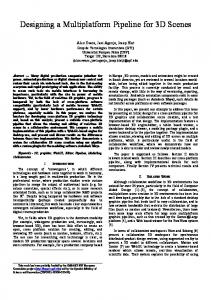
EI
Lens Array
CCD
3D Object
(a)
Lens Array LCD Display
Object Representation Observer
(b)
Fig. 1. A typical InIm (a) capturing and (b) display setup.
A method that is characterized as the near ideal multiview technique [3] functions on the principle of Integral imaging (InIm). InIm is based on Integral Photography which was initially proposed by Lipmann back in 1908 [4]. A simple InIm capturing setup is built using a CCD sensor and a lens array as shown in Fig 1. The object is projected through the lens array on the CCD surface forming a number of different projections equal to the number of the lenses in the lens array. These projections are usually called Elemental Images (EIs). An InIm display setup uses a high resolution LCD display in conjunction with an appropriate lens array to produce high quality full parallax stereoscopic images. InIm has unique characteristics that can be used for several medical, educational, entertainment and cutting edge applications [5,6] as it can provide a virtual environment with an enhanced degree of reality and 3D perception. High quality 3D object reconstruction from dynamically changing InIm scenes can further benefit these applications, provided that 3D information can be efficiently represented, stored and retrieved.
DSP 2009
implements a combined datapath that can be used for either processing task, in the form of a generic InIm processor,. Minimized memory access is achieved using a systolic architecture, and processing throughput is increased by extensive pipelining. Implementation results reveal the realtime capabilities even in the case of applying both processes on each acquired InIm. The rest of the paper is organized as follows: section 2 briefly presents the compression and reconstruction algorithms, section 3 offers an insight to the design of the architecture given a practical 3D system, and section 4 illustrates and discusses the implementation results. Section 5 concludes this paper. Fig. 2. A simplified illustration of an InIm data system combining compression and reconstruction.
However, such applications must cope with high resolution InIms which lead to high bandwidth requirements for the storage and reproduction of 3D objects and scenes. In order to target demanding real-time 3D video applications, computationally intensive tasks of both compression and representation processes must be jointly addressed with a robust acceleration method, notably hardware-oriented optimized solutions. This is necessary as the volume of information that is produced by a practical dynamic InIm system cannot be processed in real-time by the current generation of CPUs. An illustration of such a combined procedure in presented in Fig. 2. In [7], a robust technique for InIm compression is presented, targeting to high-quality imaging applications, which outperforms classic methodologies like JPEG or standard MPEG approaches [8]. The method provides high compression rates for all kinds of InIm applications while exhibiting a high degree of robustness and feasibility. The technique utilizes the fact that the EIs can be treated as a spatial sequence of subsequent frames having a predetermined motion pattern. The most time-consuming part of the aforementioned algorithm is accelerated using a hardware platform as presented in [9], achieving real-time processing rate. Additionally, a method that is focused on the reconstruction of a fully 3D surface model is recently proposed in [10], which demonstrates several advantages compared to previous attempts on the field [11-15] in terms of scene size and reconstruction quality. An attempt to accelerate this technique using a digital architecture is presented in [16]. Both hardware implementations target on efficiently implementing a comparison metric that is used to determine best matches between pixels of neighboring EIs, either for disparity estimation or for grid computations. In this work, we present a unified acceleration architecture for compression and reconstruction of 3D data, targeting to flexible real-time systems where both storage and reproduction of high-quality images and video are critical. The proposed system takes into account the common computations present in both methods and
2. COMPRESSION AND RECONSTRUCTION ALGORITHMS The 3D reconstruction method proposed in [10] utilizes a distance metric to estimate the 3D shape and texture of an object from a single InIm. The method computes vertices using the central pixel of each lens in order to form a regular sampled vertex grid, and then subdivides this grid, computes additional vertices and triangulates them to a refined grid. For the EI computations, the distance metric D ( p1 , p2 ) T
T
between two pixels ( p1 = [u1v1 ] and p2 = [u 2 v2 ] ) from
different EIs has the following formula: D ( p1 , p2 ) =
W
W
∑∑
E1 (u1 + i, v1 + j ) − E2 (u2 + i, v2 + j )
(1)
j =−W i =−W
where E1 and E2 are the two EIs, and W defines the size of the comparison window area. This metric is extended to more than two EIs. In practice, 2 N + 1 neighboring EIs are used per direction, thus forming a symmetrical neighborhood area of radius N around each EI. The best correspondence has the minimum sum of the distances over all neighbors. The compression algorithm forms a sequence of reference (I) and predicted (P) EIs (see also section 3 and Fig. 3) taking into account the additional constraints that are imposed from the properties of the InIm image data. The initial scheme proposed in [7] is extended by using different I-P topologies, which represent variations in the quality of the compressed image and the compressed image size. In order to determine the “best match” of each P block in the I-type EI, the same distrance metric (Eq. 1) is used that adds up the absolute differences between corresponding elements in the predetermined EIs. In this case, i , j are spatial coordinates in the pixel domain and E1 , E2 represent m × n pixel blocks in adjacent EIs, the size of which is defined by W . The actual coordinates of these blocks in the corresponding EIs are determined by the search algorithm
used. A similar to the reconstruction method parameter N is used to indicate the selected group of EIs.
Up neighbor
3. PRACTICAL HARDWARE SYSTEM
As mentioned in the previous section, the pixel distance metric constitutes the computational core of both algorithms. The calculation of the metric in software is timeconsuming due to the complex nature of the absolute value calculation procedure and the subsequent multitude of additions. Moreover, the repetitive nature of the metric computations favors hardware implementation in order to improve performance. Furthermore, an optimized architecture can sufficiently eliminate the redundant memory accesses of the algorithms, imposed by the traversal of the comparison window area. Taking all the above into account, a combined hardware processor that implements the distance metric is designed in a way that either process can be executed according to the momentary need of the 3D system. The distance metric described in Eq. 1 is implemented in the proposed hardware system using the Sum of Absolute Differences (SAD) metric, which is computationally simpler than the Mean Square Error (MSE) and similar to the Mean Absolute Difference (MAD) metric [17]. The hardware design is based on the parameters of a practical InIm system. For a square CCD, a resolution of 2048 × 2048 pixels offers a good compromise between image quality and acquisition rate. For a lens array with low focal length (i.e. 3.3mm) that can be fitted to the CCD, an optimal setup corresponds to 64 × 64 pixels per lens, resulting in 32 × 32 lenses (and corresponding EIs) balancing high resolution with number of different perspectives acquired by the different lenses. 3.1. Hardware specifications
For 64 × 64 pixels per EI, the optimal window for reconstruction is 11 × 11 ( W = 5 ). For this configuration, we consider a range for the neighboring area values from N = 1 to 3 [10]. In the initial grid computation step the 3D position of the central pixel of each EI is computed. In the second step, the 3D position of 3 additional pixels for each EI is subsequently calculated. According to the reconstruction algorithm and the lens size, the maximum size of the search area is 11 × 30 , which also defines the number of SAD calculations for each pixel window in the central EI. For the utilized configuration, there are 32 × 32 EIs, but we use only the inner (32 − 2 N ) × (32 − 2 N ) (so that each central EI has N neighbors per direction) to avoid possible aliasing effects between neighboring lenses. An outline of the search areas for neighboring EIs is depicted in Fig. 3a.
64 Left neighbor
Central EI
Right neighbor
(11x11)
64 Down neighbor
(a) P
64
I
(8x8)
P (8x8)
(8x64)
64
(b) Fig. 3. Outline of the search areas in neighboring EIs (a) for the reconstruction process (N=1) and (b) for the compression process (N=2).
The reconstruction operation takes into consideration that for opposite neighbors the total number of calculations remains constant. This is due to the definition of the search area which depends on the position of the block in the central EI [10]. As this block’s position moves away from the center, the size of the search area in one neighbor increases as in the opposite neighbor is reduced in the same amount. As a result, the number of SAD Units for such an implementation is defined by the maximum sum of comparison blocks in opposite neighboring EIs, which is determined to be 50 for the specific practical system. Compared with a single-neighbor approach [16], this scheme requires extra circuitry that allows the array of 50 SAD Units to operate as two sub-modules of variable size each. The central EI’s block arrives at the input of each submodule, and the neighboring blocks are distributed to the correct SAD Units. Additionally, the output of this scheme is properly wired in order to handle the variability of the additions it must carry. Each unit’s output is directed to the proper selector unit of the two available at the output selection stage, according to the comparison block coordinates of the central EI. Each selector is connected to one input of the 2to-1 adder, which adds up the SAD values of each proper pair of blocks to one intermediate value, which is stored in the temporary results BRAM.
3.2. Datapath layout
Based on the requirements of the two specific processes, the combination of the reconstruction and compression architectures to a unified digital system is presented in Fig. 4. The system is comprised of 57 SAD Units in order to carry out all the needed calculations for both processes. The first 50 Units are also used by the reconstruction process. The input and output selection stages apply only to 3D reconstruction, where the Units must operate on two search areas simultaneously, and the results to be properly forwarded to the adder inputs. The reconstruction process
Reconstruction module
SAD Unit #0
Temp. results BRAM
EI memory Up_Mem
Dn_Mem
CMem-hor
SAD Unit #2
CMem-ver /I_Mem
Ouput Selection stage
R-Pr_Mem
+
SAD Unit #1
L-Pl_Mem Input Selection stage
The systolic arrangement of the SAD Units minimize memory read operations, since the EI pixel values are only transferred once for the calculations. The successive operation of the SAD Units in an array structure removes the need for a parallel comparison unit, which would aggravate area coverage and operation speed of the system. The intermediate SAD values are temporarily stored in order to be added to the values of the next SAD calculations of the remaining two neighbors for each neighborhood level N . After the second calculation process, they are compared in order to determine the minimum value. It is this value that corresponds to the best match of the central EI block to its neighboring ones. Once the smallest value is determined, the positions of the pixels in the neighboring EIs are defined. These pixels are the best matches to the pixel that corresponds to the window of the central EI. The comparisons impose only one clock cycle delay on the process, since they begin when the first unit of the array outputs its SAD value and end one clock cycle after the last unit of the array outputs its SAD value. For the compression process, the P-type and I-type EIs are partitioned to 8 × 64 pixel areas. Moreover, each of these areas in the P-type EIs is divided to eight 8 × 8 blocks, as shown in Fig. 3b, in order to comply with the transformation computations needed for the coding process (i.e. 2D-DCT). These areas are traversed columnwise in a left-to-right direction. The applied compression scheme is PI for N = 1 , P-I-P for N = 2 and P-P-I-P-P for N = 3 . Memory read operations are minimized since the EI pixel values are only transferred once for the calculations [9]. According to the unidirectional exhaustive search method used for the best match, 57 SAD values are computed for the leftmost 8 × 8 P block in the aforementioned 8 × 64 EI area, and eight less values for each consecutive block until the last one, for which no values are computed. Due to the pipelined architecture, the computations for successive P-type blocks are performed using the same SAD Units, so only 57 SAD Units in total are needed to complete the process. The minimum SAD value for each of the 7 processed P blocks derives from the comparison of the SAD values calculated for it and takes place in the Comparison stage.
+
Comparison stage Comparator
min{SAD1} Comparator
min{SAD2 } SAD Unit #56
Comparator
min{SAD7 }
Disparity Vector 1 or best match Disparity Vector 2
Disparity Vector 7
Fig. 4. The main modules of the proposed architecture.
also uses a dedicated reconstruction module, where the intermediate and final additions take place, and the intermediate results are temporarily stored. The comparison stage is common to both processes, and contains 7 separate sequential comparators, in order to accommodate all the required comparisons of the compression process. One of these comparators is also used for the reconstruction results, in order to determine the best match for the central EI pixel window. The implemented SAD Units can process an 11 × 11 pixel window which is needed for the reconstruction calculations. Since the compression process operates on 8 × 8 block size, the block is zero-stuffed with three additional rows and columns, in order to reach the 11 × 11 size needed for the SAD Unit operations. The zero stuffing alleviates the need for different processing elements and doesn’t impose any delay on the processing time. The memory design takes into account the need for immediate access to arbitrary blocks in an EI, which is useful for the reconstruction calculations. The memory modules are designed with the ability to uninterruptedly feed the SAD array with image data at the needed rate, regardless of the block position of the central EI. On this account, 11 memory modules are used for every EI. Each of these memory modules stores pixel lines of the EI, in intervals of 11 lines. For example, in the first memory module, lines 0, 11, 22, 33 etc are stored. This way, 11 pixels of each line can be accessed in every clock cycle regardless of the pixel’s coordinates (and hence block position) in the EI. Moreover, the horizontally adjacent EIs (i.e. left and right neighbors) must be stored row-wise and the vertically adjacent EIs (i.e. up and down neighbors) column-wise. This arrangement favors fast calculations of the sums regardless of the direction of the search area. Due to the implemented search method, the central EI must be stored in two different ways, both row- and column-wise. A schematic representation of the position of pixel rows or columns in each memory module is illustrated in Fig. 5.
1 2 3 4 5 6 7 8 9 10
0
11
22
33
44
55
1
12
23
34
45
56
2
13
24
35
46
57
3
14
25
36
47
58
140
4
15
26
37
48
59
120
5
16
27
38
49
60
6
17
28
39
50
61
7
18
29
40
51
62
60
8
19
30
41
52
63
40
9
20
31
42
53
--
20
10
21
32
43
54
--
0
200
InIms/sec
0
Fig. 5. The EI’s pixel row or column positioning in each EI memory module.
The topologies of the I-type and P-type EIs in the compression process is similar to that of specific EIs in the reconstruction stage. The I-type EI can be considered as the central EI and the P-type EIs as left or right neighbors of the central EI according to the value of N . This way, the EI memory can be shared for both processes as illustrated in Fig. 4. Depending on the demanded calculations, the appropriate data are retrieved and forwarded to the SAD Units. 4. RESULTS
Table I summarizes the features of the digital system collating the reconstruction and compression processes. TABLE I MAIN FEATURES OF THE IMPLEMENTED ARCHITECTURE Process No. of oper. SAD Units Window Size (block) No. of oper. comparators Processing performance in clock cycles (cc)
Reconstruction 50 11 × 11 1 114 for 4 neighbors
Compression 57 8×8 7 80 for one 8 × 64 pixel area
The total clock cycles (cc) for finding the best match using the reconstruction metric for 4 EI neighbors adds up to 114 cc. This number breaks down to 100 cc for propagating the data two times from the first to the last of the 50 operational SAD Units and the rest cc for propagating the data through the remaining datapath (adder trees in the Units, intermediate and final adder, and sequential comparator). The compression process completes in 80 cc for one 8 × 64 pixel area, which is the cycles needed for a single read of the 8 × 64 areas in the P and I EIs, for propagating the data through the 57 operational SAD Units and for the imposed pipeline delay through the adder trees and the comparators. The implemented system can be clocked with a frequency of 86 MHz on a Virtex-5 LX110T FPGA device. Based on this timing, the architecture’s performance is evaluated for a practical 3D system for an image resolution
180
Reconstruction process
160
Compression process
100 80
1
2
3
Neighborhood area radius (N)
Fig. 6. Processing performance of the digital system for the reconstruction and compression processes.
of 2048 × 2048 pixels as explained in section 3. The compression performance is measured for the 3 different groups of EIs indicated by N . As for the reconstruction performance, 3 different neighborhood area radii are tested. The results are depicted in Fig. 6. As depicted in Fig. 6, more than 30 InIms can be processed every second by the proposed architecture for either process. In the reconstruction process, the total InIm processing rate reaches up to over 65 InIms/sec for the smallest value of N , and remains over 30 even for larger N values that signify the increase in reconstruction quality. The compression achieves rates above 80 InIms/sec even for the smallest group of EIs ( N = 1 ). It should be noted that the system achieves real-time performance even when both processes are applied to the InIm data sequentially. This is extremely useful since each InIm can be compressed and stored right after acquisition once, and then be available for 3D reconstruction or transmission as many times as needed. 5. CONCLUSIONS
Integral Imaging is a promising technology for high-quality 3D imaging applications, and it is essential to create robust InIm integrated systems in order to cope with the high data volume these systems have to manipulate. The proposed architecture tackles both compression and reconstruction of InIm data, based on the common modules that both processes share in order to determine candidate blocks for 3D coding or 3D object reconstruction. The same processing elements and memory modules can be used efficiently for either process with minor architectural tweaks, creating a unified datapath. Implementation results reveal the real-time capability in both reconstruction and compression computations, signifying the efficiency of the proposed architecture. The unified system approach shows that common 3D image processing tasks in near-future 3D imaging and video systems can be effectively handled through multipurpose integrated architectures. These simplifications can greatly reduce area requirements for
specialized hardware, reduce costs and increase the robustness of such systems in a real-time operating environment. ACKNOWLEDGMENTS
This work was realized under the framework 8.3 of the Reinforcement Programme of Human Research Manpower (“PENED 2003” – 03ED656), co-funded 25% by the General Secretariat for Research and Technology, Greece, 75% by the European Social Fund, and by the private sector. The authors would like to thank Prof. T. Theoharis and Dr. G. Passalis for their valuable comments on the paper. REFERENCES [1] Developers Handbook, Stereographics, 1997, www.stereographics.com. [2] M. Halle, “Autostereoscopic displays and computer graphics”, Computer Graphics, 31(2), ACM SIGGRAPH, pp. 58-62, 1997. [3] J. -Y. Son B. Javidi, “Three-Dimensional Imaging Methods Based on Multiview Images,” J. Display Technol. 1, pp. 125-140, 2005. [4] G. Lippman, “La Photographie Integrale,” C. R. Acad. Sci., 146, pp. 446-451, 1908. [5] H. Liao, S. Nakajima et. al., “Intra-operative Real-Time 3-D Information Display System Based on Integral Videography”, MICCAI’01, LNCS 2208, pp. 392-400, 2001. [6] P. Harman, “Home based 3D entertainment-an overview”, Proc. ICIP(1), pp. 1-4, 2000. [7] N. Sgouros, A. Andreou, M. Sangriotis, P. Papageorgas, D. Maroulis, N. Theofanous, “Compression of IP Images for Autostereoscopic 3D Imaging Applications”, 3rd International
Symposium on Image and Signal Processing and Analysis (ISPA03), Rome, Italy, September 18-20, pp. 223-227, 2003. [8] S. Yeom, A. Stern, B. Javidi, “Compression of 3D color integral images”, Opt. Express 12, pp. 1632-1642, 2004. [9] D. Chaikalis, N. Sgouros, D. Maroulis , P. Papageorgas, “Hardware Implementation of a Disparity Estimation Scheme for Real-Time Compression in 3D Imaging Applications”, Journal of Visual Communication and Image Representation, vol. 19 Issue 1, pp. 1-11, 2008. [10] G. Passalis, N. Sgouros, S. Athineos, T. Theoharis, “Enhanced Reconstruction of 3D Shape and Texture from Integral Photography Images”, OSA Applied Optics, 46:5311–5320, 2007. [11] J. Park, Y. Kim, J. Kim, S. Min, B. Lee, “Three-Dimensional Display Scheme Based on Integral Imaging with ThreeDimensional Information Processing”, Optics Express, 12:60206032, 2004. [12] J. Park, S. Jung, H. Choi, Y. Kim, B. Lee, “Depth Extraction by Use of a Rectangular Lens Array and One-Dimensional Elemental Image Modification”, OSA Applied Optics, 43:48824895, 2004. [13] S. Kishk, B. Javidi, “Improved Resolution 3D Object Sensing and Recognition using Time Multiplexed Computational Integral Imaging”, Opt. Express 11, 3528-3541, 2003. [14] Y. Frauel, B. Javidi, “Digital Three-Dimensional Image Correlation by Use of Computer-Reconstructed Integral Imaging”, Appl. Opt. 41, 5488-5496, 2002. [15] D. Shin, E. Kim, B. Lee “Computational Reconstruction of Three-Dimensional Objects in Integral Imaging Using Lenslet Array”, Japanese Journal of Applied Physics, 44/11:8016-8018, 2005. [16] D. Chaikalis, G. Passalis, N. Sgouros, D. Maroulis, T. Theoharis, “Near Real-Time 3D Reconstruction from InIm Video Stream” ICIAR 2008, LNCS 5112, pp. 336–347, 2008. [17] Wong S., Vassiliadis S., Cotofana S., “A Sum of Absolute Differences Implementation in FPGA Hardware” 28th Euromicro Conference, Dortmund, Germany, pp. 183-186, 2002.