The images show vector data of buildings, streets and runway (from left to right). Abstract. ... mapping techniques to project it onto the mesh during rendering.
Real-time Rendering of Complex Vector Data on 3d Terrain Models M. Schneider, M. Guthe, and R. Klein1 Universität Bonn, Römerstraße 164, 53117 Bonn, Germany
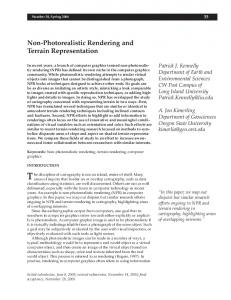
Figure 1: Rendering of vector data with our technique on a terrain data set of Turtmann valley (Switzerland). The images show vector data of buildings, streets and runway (from left to right). Abstract. In this paper we present a hybrid technique that is capable of precisely and efficiently overlaying 2d geo-spatial vector data on a 3d multiresolution terrain model. The first part of this hybrid technique is a texture-based approach that is especially suited for applications that demand high flexibility since it allows the modification of the vector data through user input in real-time. This is faciliated by an efficient method to generate textures on-the-fly in an offscreen buffer. Quality superior to standard texture mapping is achieved by using a perspective reparameterization similar to that applied in perspective shadow mapping. The second part is a geometry-based approach that is addressed to applications focused on high quality visualizations. In a preprocessing step 3d geometry is created from the 2d vector data for each level-of-detail of the terrain and completely incorporated into the terrain quadtree hierarchy. The combination of the two approaches in one terrain rendering framework enables the user to choose the method according to his demands and to benefit from the advantages of both techniques.
1. Introduction In geoscience analytical vector data represents one of the main categories managed by geoinformation systems. The vector data is typically represented by lists of coordinates defining points, lines, polygons, etc. These primitives are traditionally used for describing geographic entities, for example buildings, rivers, and vegetation or soil types (see Figure 1). In general there are two basically different approaches to visualize 2d vector data on a 3d mesh. One option is to rasterize the vector data into a texture and use standard texture mapping techniques to project it onto the mesh during rendering. The other option is to map the vector data to 3d geometric primitives and to render them as separate geometry with an additional offset. Both techniques comprise a number of challenges. 1
{ms,guthe,rk}@cs.uni-bonn.de
Figure 2: Geometry-based approach: simply mapping the vertices contained in the vector data is not sufficient (left), correctly mapped vector data with newly introduced vertices and edges (right).
Rasterization of the 2d vector data into a texture in a preprocessing step and then rendering the terrain using standard texture mapping implies several drawbacks. The frequently needed combination of several layers of geo-spatial data demands a separate texture for each data layer resulting in high memory requirements. Multitexturing techniques have to be applied to project the textures for different geospatial information onto the textured terrain. What is worse, the accuracy of the vector data is bound by the texture resolution leading to unpleasant results when zooming in and single texels become visible. This contrasts to the geometry-based approach where the accuracy is independent from the resolution of an applied texture. Most 3d representations are based on a level-of-detail terrain model which is needed to handle large terrain data sets and whose geometry is refined according to the viewpoint. If vector data is mapped to such a multiresolution structure, it has to be adapted to the current level-of-detail in order to avoid rendering artifacts (see Figure 2). Unfortunately, this procedure leads to an increase in the number of geometric primitives compared to the original 2d vector representation. Furthermore, a suitable z-offset has to be added to the created primitives during rendering in order to avoid z-buffer stitching artifacts. In this paper we present a hybrid system allowing a combination of both techniques accounting for their advantages and drawbacks. Our work is build upon the terrain rendering system presented by Wahl et al. [10] and permits the overlay of vector data as geometry and texture. Since, depending on the actual application area, one method is more suitable than the other, a coexistence and the possibility to combine both approaches in one terrain rendering framework is essential to fulfill the needs of users with various backgrounds resulting in different demands and priorities. In the texture-based part of our method we create a texture on-the-fly using an offscreen buffer and project it onto the terrain using a perspective reparameterization similar to the light space perspective shadow map approach [13]. The on-the-fly texture creation process guarantees high flexibility to react to modifications of the vector data. Its efficient creation is assured by utilizing a method recently suggested by Guthe et al. [3], which is able to efficiently rasterize non-convex polygons and polygons with holes that are a common part of 2d GIS vector data. For the geometry-based part of our system the vector data is mapped to each level-of-detail of the quadtree hierarchy, thereby creating a 3d multiresolution geometry representation of the vector data. This enables a seamless integration into the existing visualization system and therefore, permits efficient rendering. Using the same level-of-detail during rendering for geometry and vector data prevents the above mentioned artifacts. The remainder of this paper is organized as follows: after a disussion of previous work in Section 2, we describe our texture-based approach in Section 3 and the geometry-based technique in Section 4. We evaluate and discuss the methods in Section 5 and draw conclusions in Section 6.
2. Previous Work Our approach of combining the visualization of traditional GIS vector data with a level-ofdetail terrain model builds upon work in the field of terrain rendering. Multiresolution algorithms for fast rendering of terrain data with viewport adaptive resolution are still an active area of research [1]. Since giving a complete overview is beyond the scope of this paper, we refer to recent surveys [6, 7]. Our work is based on the terrain rendering system developed by Wahl et al. [10]. It subdivides geometry and textures into equally sized blocks and organizes them in a quadtree. Each block is represented by a triangulated irregular network (TIN). The decision whether to render a node or to refine it is made on a per quadtree node basis. This means that each quadtree node holds a precomputed and simplified triangulation. The method facilitates high quality rendering in real-time even with very large input data. Work that deals with the visualization of vector data on 3d terrain is relatively rare. A texture-based approach to visualize vector data was proposed by Kersting et al. in [4]. Textures containing the vector data are generated on-the-fly using p-buffers. They use an ondemand texture pyramid that associates equally sized textures with each quadtree node to improve visual quality when zooming in. Unfortunately, many expensive p-buffer switches are needed decreasing rendering performance. Even with more recent and efficient extensions (e.g. f-buffers) each switch still requires a complete pipeline flush. Wartell et al. [11] presented an algorithm and an associated data structure that allows rendering of 2d polyline vector data on a multiresolution terrain mesh. Since their system is based upon the classic algorithm by Lindstrom et al. [5] that uses a continuous level-of-detail approach, they have to adapt the polyline in each frame to the current state of geometry resulting in decreased rendering performance and increased memory requirements for the additonal data structures that are needed. 3. Texture-based approach A simple approach to visualize 2d vector data on arbitrary surfaces is to use texture mapping. In our approach, the generation of the textures is performed on-the-fly by using an offscreen buffer (e.g. a p-buffer or f-buffer when available). First, we describe a method for texture generation that efficiently handles non-simple polygons that are common primitives in geodata. Then we propose a perspective reparameterization of this texture similar to
Figure 3: Concave polygon with hole (left), counting texel coverages (right).
perspective shadow mapping. This reparameterization of the on-the-fly texture improves visual quality compared to standard texture mapping with nearly no overhead. 3.1. Efficient on-the-fly texture creation We use an algorithm presented by Guthe et al. in [3] to render the vector data into an offscreen buffer. It is especially suited for rendering non-convex polygons and polygons with holes, which do not need to be triangulated. The algorithm is inspired by the standard approach for area calculation of polygons. The main idea is, that when spanning a triangle fan from the first vertex of each polygon ring, a point inside this ring will be covered by an odd number of times as shown in Figure 3. Instead of counting the coverages, it is possible to simply consider the lowest bit and toggle between black and white. A big advantage of this approach is that we do not need to take care of the orientation and nesting of the polygon rings and thus error prone special case handling is avoided. The toggling of pixels is performed using alpha blending. Note that with this procedure the entire alpha texture for a GIS layer can be generated in a single rendering pass. If only a single layer is rendered, the alpha texture can be directly used in a fragment shader. The color of the layer can be defined by setting an appropriate vertex attribute which is then multiplied in the shader before blending. When multiple layers are activated for rendering, we first need to combine them into a single texture. This is performed by accumulating the layers in a second offscreen buffer of the same size using standard alpha-blending. No specialized shader is required for accumulation, since the primary color can be used to specify the color of the current layer. This way, an arbitrary number of possibly semitransparent layers can be rendered on the terrain with only two additional textures. Since the required texture size would become huge, if uniform texture coordinates were used, a reparameterization is needed. 3.2. Texture reparameterization First, we briefly formalize the arising aliasing problem of the texturing process (see Figure 4). Each texel of size d t × d t of the vector data texture is orthogonally projected into the scene. If a surface is hit under an angle β , the size of the projection is d t / cos( β ) . In the final
Figure 4: Aliasing in texture mapping.
image the projection area of the texel has size:
d=
dt rv cos(α ) , ri cos(β )
where α is the angle between viewing direction and surface normal, ri is the distance from the camera to the surface and rv is the distance from the camera to the image plane. Undersampling occurs when d is larger than the image pixel size d i . This can happen when (d t rv ) / ri becomes large. This problem is called perspective aliasing and typically happens when the user zooms into a boundary of the vector data. Due to limited memory, the resolution of the vector data texture can only be increased up to a certain limit in practice. In shadow mapping, perspective aliasing is significantly reduced by reparameterizing the shadow map. In order to improve the visual quality of the mapping of the vector data, we propose a perspective reparameterization of the on-the-fly created texture depending on the current view by adapting the technique used in perspective shadow mapping. In shadow mapping [12], the scene is first rendered from the view of the light, storing the depth values in separate buffer. When the scene is then rendered from the normal viewing position, each pixel is transformed again into the light view and its depth value is compared to those stored in the shadow map. Perspective shadow maps [9] attempt to reduce perspective aliasing and thus improve shadow quality by performing a perspective reparameterization. Further improvements of perspective shadow mapping were presented by Wimmer et al. [13], which we use in our work. The idea of our approach is to perform the texture generation in post-perspective space. This significantly reduces perspective aliasing that is caused by the perspective projection of the viewer. The rendering process is then performed as follows. The current view frustum V is enclosed with an appropriate frustum P that has a view vector perpendicular to the projection direction of the vector data (Figure 5). By varying the length of this frustum the strength of the warping effect can be controlled. The perspective transformation induced by this frustum P is applied in two places, namely during the generation of the vector data texture and in the texture coordinate generation during rendering. In contrast to perspective shadow mapping we have no lighting but a projection direction in which we want to map the vector data onto the terrain. Instead of rendering the whole scene
Figure 5: An example configuration with scene S, view frustum V, frustum P defining the perspective transform and projection direction d. Before the perspective transform (left) and after the perspective transform (right).
Figure 6: Renderings generated with the texture-based approach only: combination of two semi-transparent layers (left) and aliasing due to texture filtering with a reduced offscreen buffer size of 512×512 (right).
from this direction and storing depth values as in shadow mapping, we simply render the vector data into the offsreen buffer using the method already described. During rendering of the terrain, the offsreen buffer is bound or copied to a texture and appropriate texture coordinates are generated according to the perspective projection of P. These texture coordinates are then used to access the previously created texture. In Figure 6 renderings generated with the texture-based approach only are shown. The left image shows the combination of two semi-transparent layers. Since, despite the reparameterization, no one-to-one mapping between texels and pixels on screen is possible, slight aliasing artifacts can still occur as shown in the right image. However, if a texture resolution of 2048×2048 is used for a 1280×1024 screen resolution, virtually no aliasing can be observed. For higher screen resolutions the offscreen buffer size would need to be increased proportionally, so that it is always at least as large as the current viewport. 4. Geometry-based mapping The geometry-based part of our method consists of two stages. The first stage is a preprocessing step, in which the multiresolution geometry is created from the 2d vector data and the according TINs used for terrain rendering. This preprocessing has to be executed only once and the resulting geometry is encoded and stored. During the rendering stage the vector geometry associated with the quadtree nodes that have been selected for display are loaded, decoded, and rendered. 4.1. Preprocessing
In the preprocessing step, the multiresolution geometry for the vector data is created by projecting the vector data on the 3d terrain geometry, which is performed in a hierarchical manner. Each primitive of the vector data is clipped against the bounding box associated with the quadtree root node. If the result is not empty, the triangles associated with this quadtree node are projected into the plane containing the vector data. After that, the intersections of the clipping result and the projected triangles are computed. In the case of polylines this simply means several line intersection tests in 2d. The zcoordinates of the resulting intersection points can afterwards be evaluated as the linear combination of the z-coordinates of the two points constituting the edge of the involved triangle segment, whereas the weights correspond to the intersection ratio of the segment. Proceeding this way allows to perform all computations in 2d. This is much more stable than to evaluate ray-ray intersection tests with the triangle segments in 3d.
Figure 7: Original terrain geometry (left) and terrain with mapped vector data (right).
In the case of polygonal vector data, we proceed as described above with the polygon borders. Additionaly, all triangles of the original terrain geometry lying inside the polygonal area are added to the vector geometry. Remaining polygonal areas in the interior of the vector polygon are triangulated and then inserted. We recursively apply this method to the child nodes until the clipping result is empty or we have reached a leaf node. Thus, this procedure is carried out for each level-of-detail. The resulting multiresolution geometry is encoded using a method similar to those described in [2, 8] and allows efficient encoding of connectivity. The decoding of the vector geometry is performed along with the decoding of the according terrain geometry at runtime. 4.2. Rendering
Rendering of the GIS data geometry is now straightforward. Because of the multiresolution representation of the vector geometry constructed in the preprocessing step, rendering vector data geometry is performed in the same way as rendering the terrain geometry. The only difference is, that now each quadtree node holds additional vector data, that can be rendered whenever the user wants to visualize it. Rendering then proceeds as follows: the quadtree is traversed in a top-down approach. For each visited node, the algorithm checks, whether the node is visible and satisfies the user imposed error bound. If a node fulfills these conditions, the geometry associated with this node is rendered, otherwise the traversal is continued. In the case, that the currently rendered node contains vector data geometry, it is rendered with an added z-offset in order to avoid zbuffer artifacts. For a more detailed discussion of the rendering procedure see [10]. 5. Results and Discussion Rendering vector data as geometry has the advantage that it produces high quality visual results. The original 2d geographic entity is converted to 3d geometric primitives whose accuracy is independent of the textures used and is therefore not limited to texture resolution. Therefore, it does not suffer from the problems of texture-based approaches when zooming in, namely that individual texels become visible. Even the use of multiresolution textures can only alleviate this problem. The geometry representation of vector data allows to further enhance the visual quality by applying texturing, lighting, etc. to it, independent of the original terrain geometry. In addition, vector geometry also permits quantitative measurements, for example length calculations.
geometry texture no vector data
runway 41 43
buildings 40 43 43
streets 37 42
Table 1: Framerates for the Turtmann valley dataset (24k×8k heightmap resolution) for different vector data layers with the geometry- and texture-based approach and without vector data.
The advantage of our approach is that we do not need to perform costly operations at runtime to adapt the vector data to the geometry. This together with the multiresolution representation of the vector data allows the real-time visualization of large input data. Furthermore, our system is not restricted to the here addressed 2d GIS vector data. Other data can simply be incorporated in our system in the same way. A drawback of the geometry-based method is that the in the preprocessing step created geometry is static. This means that the vector data cannot be manipulated by the user at runtime since the creation of geometry that has to be performed for each level-of-detail cannot be carried out in real-time. Another disadvantage of this approach emerges when a dataset contains several overlapping large areas. In this case the storage requirements, both for disk space and main memory, become huge. Therefore, the texture based approach is more suitable for large polygonal or modifyable vector data. The on-the-fly generation of the texture has the advantage that no texture or even a complete texture pyramid has to be precomputed and loaded into memory. Instead of that, only the much more compact polygonal representation of the vector data is required. With the utilization of the perspective reparameterization, aliasing artifacts are significantly reduced and a quality superior to standard texture mapping is achieved. Note that the good performance of the texture-based approach (see Table 1) depends on the availability of appropriate hardware support, i.e. a way to efficiently create a texture on the graphics hardware. If the CPU has to be involved in the texture generation and the texture has to be sent over the bus, performance significantly decreases due to bus bandwidth limitations. In cases of missing hardware support, for example on PDA’s, the geometry-based method is likely to perform superior. Another situation in which the geometry-based approach might be preferable is at very high resolutions, that is 2048x1536 and above, where there might not be enough memory available to adapt the offscreen buffer size to the screen resolution since the memory requirements for terrain rendering are already very high. Real-time renderings of our hybrid system are shown in Figure 8. 6. Conclusions We have presented a hybrid visualization system for rendering 2d geo-spatial data on complex 3d terrain allowing the user to choose the method according to his needs. Both of the presented techniques contain improvements over existing ones. The geometry-based part represents the vector data as a multiresolution geometry hierarchy by incorporating it into the terrain model quadtree, while the texture-based part employs an efficient way to generate textures on-the-fly and a perspective reparameterization depending on the viewpoint to reduce perspective aliasing.
References [1] Asirvatham A., and Hoppe H., Terrain Rendering Using Geometry Clipmaps, GPU Gems 2, AddisonWesley, 2005 [2] Gumhold S., and Straßer W., Real time compression of triangle mesh connectivity, SIGGRAPH ‘98 Conference Proceedings, pp. 133-140, 1998 [3] Guthe M., Balázs Á., and R. Klein, GPU-based Trimming and Tesselation of NURBS and T-Spline Surfaces, To appear in the ACM SIGGRAPH conference proceedings, 2005 [4] Kersting O., and Döllner J., Interactive Visualization of Vector Data in GIS, In Proceedings of the 10th ACM International Symposium on Advances in GIS, 2002 [5] Lindstrom P., Koller D., Hodges L., Ribarsky B., Hodges L., Ribarsky B., Faust N and Turner G., RealTime Continuous Level of Detail Rendering of Height Fields, In Proceedings of SIGGRAPH, 1996 [6] Lindstrom P., and Pascucci V., Terrain simplification simplified: A general framework for viewdependent out-of-core visualization, IEEE Transaction on Visualization and Computer Graphics [7] Pajarola R., Overview of quadtree based terrain triangulation and visualization, Technical Report UCI-ICS TR-02-01, University of California, Irvine, 2002 [8] Rossignac J., Edgebreaker: Connectivity compression for triangle meshes, IEEE Transaction on Visualization and Computer Graphics, vol. 5(1), pp. 47-61, 1999 [9] Stamminger M., and Drettakis G., Perspective Shadow Maps. In SIGGRAPH 2002 Conference Proceedings [10] Wahl R., Massing M., Degener P., Guthe M., and R. Klein, Scalable Compression of Textured Terrain Data, In Journal of WSCG, 2004 [11] Wartell Z., Kang E., Wasilewski T., Ribarsky W., and Faust N., Rendering Vector Data over Global, Multiresolution 3D Terrain, Joint EUROGRAPHICS – IEEE TCVG Symposioum on Visualization, 2003 [12] Williams L., Casting Curved Shadows on Curved Surfaces, In Computer Graphics (SIGGRAPH ’78 Proceedings) [13] Wimmer M., Scherzer D., and Purgathofer W., Light Space Perspective Shadow Maps, Eurographics Symposium on Rendering, 2004
Figure 8: Real-time renderings generated with our hybrid system.