Reclipse â A Reverse Engineering Tool Suite. Technical Report tr-ri-10-312. Markus von Detten, Matthias Meyer, Dietrich Travkin. Software Engineering Group ...
Reclipse – A Reverse Engineering Tool Suite Technical Report tr-ri-10-312 Markus von Detten, Matthias Meyer, Dietrich Travkin Software Engineering Group, Heinz Nixdorf Institute Department of Computer Science, University of Paderborn, Germany
[mvdetten|mm|travkin]@upb.de ABSTRACT Design pattern detection is a reverse engineering methodology that helps software engineers to analyze and understand legacy software by recovering design decisions and thereby providing deeper insight into software. In this report we present Reclipse, a reverse engineering tool suite based on Fujaba. Reclipse provides static and dynamic design pattern detection in combination with a pattern rating that is used to evaluate the quality of our detection results.
Categories and Subject Descriptors D.2.7 [Software Engineering]: Distribution, Maintenance, and Enhancement—Restructuring, Reverse Engineering, and Reengineering; D.2.11 [Software Engineering]: Software Architectures—Patterns
General Terms Languages, Algorithms
Keywords Design pattern detection, static analysis, dynamic analysis, detection results rating
1.
INTRODUCTION
Due to requests for new features and the discovery of defects, software has to be continuously extended and adapted during its life cycle. Incomplete documentation often complicates this task and is among the reasons that software engineers often spend 50 % to 75 % of a system’s total development time on maintenance [20]. The tedious and error-prone task of understanding a large system can be supported by reverse engineering tools that recover the design of the software by locating implementations of design patterns as they were published, e.g. in the seminal book by Gamma et al. [7]. Identifying instances of these patterns can help the re-engineer to understand a software system quickly, since the pattern instances hint at the original developers’ design intentions. The knowledge of design deficiencies (e.g. bad smells [5] and anti patterns [3]) and the corresponding recommended refactorings [12] can guide the reengineering task and thereby speed up the maintenance process. Since the publication of numerous design patterns, several approaches for their detection in existing software have been developed, most of which carry out a static analysis of a software’s source code [1, 4, 8, 9, 18, 19, 22]. uch an
analysis is able to recognize mainly the structural aspects of a pattern. Some patterns, however, possess characteristic behavior (only) or are structurally similar to others (as e.g. Strategy and State [7]). A purely static analysis fails to recognize or distinguish those patterns or it produces too many false positives. Consequently, we developed a pattern detection approach that integrates a static analysis to recognize structural pattern instances [16] with a subsequent dynamic analysis to also verify the runtime behavior of the detected instances [23, 25, 26]. The re-engineer must be able to recognize new patterns or to adapt the detection to specific characteristics of the analyzed system. Therefore, we offer a flexible, graphical specification of structural and behavioral patterns based on an arbitrary, exchangeable meta-model which keeps our approach largely language-independent. This also allows us to apply our approach for the detection of e.g. bad smells [13, 14] and to detect design guideline violations in Matlab Simulink models [21]. Static and dynamic analyses are also combined in the approaches of Hayashi et al. [10] and Heuzeroth and al. [11]. Hayashi et al. however use hard coded patterns, whereas we employ graphical yet formal pattern specifications. Heuzeroth et al. use Prolog for the specification of the behavioral patterns. According to the authors these specification can become very complex and are hardly maintainable. There are usually many variants for implementing a single design pattern [17]. In order to detect all those variants, a lot of pattern specifications would be needed. To avoid this, we allow the re-engineer to specify the invariant structural core of a pattern and to extend this core by additional structural elements. Those additional elements are used to automatically compute a rating of concrete instances: they need not be present for a pattern instance to be recognized, but if they are, the instance more closely resembles the specification and receives a higher rating. This way, less specifications are needed and the rating can be used to sort the static analysis results according to their completeness. In this report we present the approach and especially its implementation as a plug-in for the Eclipse IDE, the Reclipse Tool Suite1 . We also report on some evaluation results obtained by using the tool.
2.
THE APPROACH
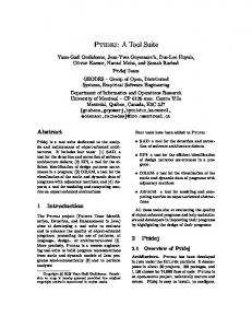
Figure 1 shows our pattern detection process. In a first step, a static analysis searches the source code of a software 1
http://www.fujaba.de/reclipse
Structural Patterns
Traces Traces
Source Code Program Execution
Static Analysis
Behavioral Patterns Dynamic Analysis
Document Process Step Data Flow
Pattern Candidates
Accepted / Rejected Pattern Candidates
Figure 1: The pattern detection process system for instances of structural patterns.Before analysis, the source code is parsed into an abstract syntax graph representation. Based on this representation, implementations of structural patterns, that are previously specified by the re-engineer, are searched. The structural patterns are specified graphically and formally by means of graph transformation rules. The result of the static analysis is a set of code fragments that comply with the structural pattern specifications. We call these fragments pattern candidates. A dynamic analysis is used to confirm or reject the candidates depending on their runtime behavior. The candidates’ expected behavior is described with formal behavioral patterns based on UML 2.0 sequence diagrams. Each behavioral pattern corresponds to a structural pattern and references its elements, e.g. object types and methods. After detecting the pattern candidates in the static analysis step, the software system under analysis is executed, and the candidates’ behavior is traced. Note that not the complete program behavior is traced but only that of the candidates. This drastically reduces the search space for the dynamic analysis. A number of traces is generated for each candidate. The traces are then compared to the behavioral patterns and it is evaluated how many of a candidate’s traces conform to the pattern. Based on the number of conform traces, the re-engineer can decide if a candidate is an actual pattern instance (i.e. a true positive) or a false positive.
2.1
Static Analysis
Throughout this report we use the Observer pattern to explain our pattern detection approach. Gamma et al. describe the Observer pattern’s intent as follows: ”Define a one-to-many dependency between objects so that when one object changes state, all its dependents are notified and updated automatically.” [7] The state changing object is usually called Subject while the dependent objects are referred to as Observers.
Structural Pattern Specification and Detection Formally, a structural pattern specification defines a graph transformation rule. An inference algorithm [16, 15] applies the different rules to the abstract syntax graph representation of a software and thus tags pattern candidates with annotations. Figure 2 shows our structural specification of the Observer pattern in an extended version of the notation introduced by Niere et al. [16, 15]. We use special UML object diagrams to specify an object structure (displayed in black), which has
to be found in the abstract syntax graph representation of a software system. Thus, the object types refer to a metamodel for the abstract syntax of object-oriented code, in this case Java. The structure to be found contains two classes: subjectClass and observerClass. Note that the object names in the pattern specification are variables that are matched to real objects during the detection process. The subjectClass has the methods register, which takes an observerClass object as parameter, and notify. The observerClass has an update method. The ellipses are so-called annotations and refer to subpatterns which are specified in other diagrams. Annotations represent instances of subpatterns. In this case the annotations indicate that the subject class’ notify method must implement a delegation to the observer class’ update method. The OverridingMethod annotation concreteUpdate states that the method update should be overidden2 . The MultiReference annotation reference expresses that a subject references arbitrarily many observers. Finally, the Observer annotation that is displayed in green and marked with �create� is created when the depicted structure is found. The annotation tags the structure as candidate for the Observer pattern.
Pattern Variants and Rating of Pattern Candidates In order to enable the recognition of different variants of a pattern with a single specification, we introduce the concept of additional constraints. They allow us to specify conditions whose satisfaction is desired but not mandatory to constitute an actual pattern instance. In case of the Observer pattern, the subjectClass and observerClass should be abstract and subclassed to reduce the coupling between the concrete classes [7]. Since this is often neglected in practice, we mark those constraints in the pattern specification as {additional}. This way, we recognize both, Observer candidates with abstract and nonabstract classes. If the classes are abstract in a candidate, however, that candidate more closely resembles the pattern’s intended structure. Consequently, such a candidate receives a higher rating than others. In addition, when subclassing is used, the observer’s update method should be overridden multiple times. This is specified by the set annotation concreteUpdate, displayed as a stacked ellipse. The set annotation is additional, indicated by its dashed border. With the additional expression SIZE ≥ 1 we want to rate candidates higher, for which the set contains at least one element, i.e. the update method is overridden at least once. We use the information given by the satisfaction of additional constraints to separate reliable from less reliable results. This is done automatically by rating each pattern candidate with a value on a percental basis that relates the number of constraints satisfied by a candidate to the total number of constraints in the corresponding pattern specification. The more constraints are satisfied the higher is the rating value. Additionally, weights can be used to increase or decrease the impact of a constraint’s (dis)satisfaction. The rating quantifies the degree of a pattern candidate’s compliance to 2
According to Gamma et al. the observer and subject classes are intended to be subclassed by concrete observers and subjects that implement their own specific behavior.
sp Observer «create» :Observer
«create» subject
«create» observer
bp Observer
stereotype:UMLStereotype name: String = "interface"
s:subjectClass
oSet:observerClass
stereotypes subjectClass:UMLClass
observerClass:UMLClass
abstract: Boolean = true {additional}
abstract: Boolean = true {additional} referencingClass
methods
loop (1,*)
reference:MultiReference
paramType
register(o:observerClass)
methods
methods param register:UMLMethod
notify:UMLMethod
loop (1,*)
referencedClass
caller
loop (1,*)
p:UMLParam callee
delegation:Delegation
notify() each
update:UMLMethod overridden
update()
concreteUpdate:OverridingMethod SIZE ≥ 1 {additional}
Figure 2: Observer structural pattern its specification and helps the reverse engineer to distinguish true from false positives. Moreover, a threshold can be set in order to display only pattern candidates with a rating higher than the threshold.
2.2
Dynamic Analysis
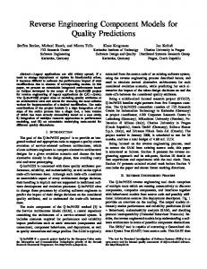
Figure 3 illustrates the expected behavior of the Observer pattern in the syntax defined by Wendehals et al. [24, 23, 25]. It shows one object s of the type described by the subjectClass node in Figure 2 and a set of observer objects oSet. The object types and message names refer to identifiers from the structural pattern specification (cf. Figure 2). Objects of the type observerClass call the register method of the subjectClass to register themselves for the subject’s updates and are therefore considered as members of the set oSet. This can happen 1 to arbitrarily many times as specified by the loop fragment. The following loop fragment indicates that whenever s calls its notify method the update method of each object in the set has to be called. The whole pattern is enclosed in another loop fragment because the specified behavior may be repeated several times. If an Observer candidate fails to show this behavior, it is probably a false positive (or a variation of the design proposed by Gamma et al. [7] that does not match our specification). The dynamic analysis is based on traces of the pattern candidates identified by the static analysis. To obtain these traces, the system under analysis is executed and method calls between instances of classes that are part of a candidate are recorded. In the Observer example only methods that have been identified as candidates for the methods register, update and notify are traced. During the analysis step, the traces are compared to the corresponding behavioral patterns. For this purpose, a special automaton is automatically generated for each behavioral pattern. If a trace matches the pattern, it is accepted by the automaton and rejected otherwise [26]. If the majority of a candidate’s traces match the behavioral pattern, it is likely that the candidate is an actual design pattern implementation. If most of the traces for a candidate do not match the behavioral pattern, it is assumed to be a false positive.
Figure 3: Observer behavioral pattern
3.
EVALUATION RESULTS
We used our prototype implementation in the Reclipse Tool Suite to evaluate the approach by analyzing e.g. Java’s Abstract Window Toolkit (AWT) [15], the Java Generic Library (JGL) [15], Eclipse’s Standard Widget Toolkit (SWT) [14, 25] and JHotDraw 6.0 beta 1 [14]. In order to be able to compare our results with those of other approaches [8, 9, 22] we also performed an analysis of JUnit 3.8.23 the results of which we chose to present here. The analyzed version consists of 93 Java classes (including test and example files). Our pattern catalog contains 8 GoF patterns and 12 (auxiliary) subpatterns. Table 1 shows our analysis results. For each pattern, column ”# Cand.” contains the number of pattern candidates found by the static analysis, the column ”# TP” lists the number of true positives (TP) for each pattern, while column ”Rating” shows the lowest and the highest rating that the pattern candidates received. We detected 1 candidate each for Composite and Decorator, 5 Template Method candidates, 17 Command candidates, and 10 Observer candidates. The Composite candidate is a true positive that was documented by JUnit’s designers Gamma and Beck [2]. It was also detected by other approaches [8, 4, 22, 9]. The Decorator candidate was also detected by those other approaches. It is not explicitly documented but the names of the participating classes (Test and TestDecorator) and their implementation reveal that the candidate is a true positive. Since the structure of the Template Method pattern is rather simple, we could confirm the candidates to be true positives by manual inspection. The template method described by Gamma and Beck [6] was not detected because the final implementation deviates heavily from the actual Template Method pattern. Due to their complex structure the Command and Observer candidates were harder to verify by manual inspection. We used the dynamic analysis to further analyze these patterns. The ”Dynamic Analysis” column shows the number of accepted and rejected candidates respectively. We found 17 candidates for Command pattern implementations with varying ratings. The highest rated candidate with 74 % had indeed a structure that was very similar to 3
www.junit.org
Pattern Composite Decorator Template Method Command Observer
# Cand.
# TP
1 1 5 17 10
1 1 5 0 1
Rating lowest highest 83 % 83 % 91 % 91 % 100 % 100 % 47 % 74 % 38 % 81 %
Dynamic Analysis accepted rejected – – – – – – 0 17 1 9
Precision excl. dyn. incl. dyn. 100 % – 100 % – 100 % – 0% 100 % 10 % 100 %
Table 1: Analysis results
the Command pattern. Its behavior however did not match the expected pattern, so our dynamic analysis rejected it as a false positive. The other candidates were equally rejected. Our manual inspection confirmed the Command pattern candidates to be false positives. The ten Observer candidates, that were detected, received ratings between 38 % and 81 %. All candidates share certain similarities with the Observer pattern, but our manual inspection revealed that most of them are false positives. The lower rated candidates implement a to-one-reference between the alleged subject and the observer instead of the required to-many-reference. The dynamic analysis accepted only the candidate with the highest rating as an actual Observer instance. This complies with our manual inspection. Contrary to the findings reported by Tsantalis et al. [22], we could not find instances of the State / Strategy pattern in JUnit. Other analyses support this result [8, 9]. For each listed pattern in Table 1 we also determined the achieved precision. Here, we distinguish the precision of the purely static analysis, excluding the results of the dynamic analysis (column ”excl. dyn.”), and the precision achieved by combining the static and dynamic analysis results (column ”incl. dyn.”). Since the dynamic analysis rejects pattern candidates that do violate the behavioral patterns, the number of false positives is significantly reduced. In this case, we reach an overall precision of 100 % for the JUnit example. However, we still have to apply our dynamic analysis approach to bigger software systems to yield statistically more relevant results. The runtime of the static analysis heavily depends on the number of specified patterns and, of course, on the size of the analyzed system. The analysis of JUnit took 4 seconds for the parsing of the code and 14 seconds for the static pattern detection. The dynamic analysis for a trace with 700 method calls took less than one second. These results were obtained on a Core 2 Duo P8600 CPU with 2.4 GHz and 4 GBytes of RAM.
4.
CONCLUSIONS AND FUTURE WORK
In this report we presented our reverse engineering approach and the corresponding tool Reclipse which has been under development in our research group since 1999. The major advantages compared to other approaches are the combination of static and dynamic analysis for the detection of (design) patterns in the source code of a software system as well as its flexible, yet formal way of structural and behavioral pattern specification, that enables the re-engineer to extend and adapt the specifications. Furthermore, the approach allows to specify several structural variants of a pattern at once by means of additional elements which are likewise used to automatically rate de-
tected pattern candidates. We presented some evaluation results showing that our approach and its implementation are mature and efficient enough to be applied to real systems. The large number of candidates that were rejected by the dynamic analysis may indicate that our structural specifications of the Command and Observer patterns are too imprecise and hence yield so many false positives. On the other hand, it illustrates the usefulness of the dynamic analysis as a means of distinguishing true from false positives. In the future, we plan to apply the dynamic analysis on larger software systems than JUnit to yield statistically more relevant results. Furthermore, we want to facilitate the usage of fuzzy values in metric constraints. We also want to integrate the concept of additional constraints into the behavioral patterns and intend to provide better support for the interpretation of dynamic analysis results.
5.
ACKNOWLEDGMENTS
We would like to thank J¨ org Niere, Lothar Wendehals and Marie Christin Platenius for their conceptual work on the approach and their help in implementing Reclipse.
APPENDIX A.
EXAMPLE SESSION
In this example session we present the Reclipse Tool Suite by stepping through the reverse engineering process illustrated in Figure 1. We chose the JUnit 3.8.2 framework for the analysis since its design is documented by its developers [2] and several reverse engineering approaches were already evaluated on the same framework [4, 8, 9, 22]. For the example session we assume that we are re-engineers trying to get familiar with the JUnit framework by recovering its design. For that purpose structural and behavioral patterns are specified, a static analysis is performed, and, in cases of unassured pattern candidates, complemented by a dynamic analysis in order to reveal the pattern candidates as actual pattern instances, i.e. true positives, or as false positives.
A.1
Software Pattern Specification
In order to automatically detect software pattern instances in source code we have to formally specify the pattern’s structure and, where reasonable, its behavior. For that purpose Reclipse provides the required editors. The structural pattern in Figure 2, for example, is specified using the structural pattern specification editor illustrated in Figure 4. The behavioral pattern in Figure 3 is created with another editor. We described the structural and behavioral Observer patterns in Sections 2.1 and 2.2.
Figure 4: Observer structural pattern specification in Reclipse
Figure 5: Delegation structural subpattern As shown in Figures 2 and 4 the structural Observer pattern specification is based on other patterns like Delegation (Figure 5) and MultiReference (Figure 6). Such common, auxiliary subpatterns can be re-used to specify other, more complex patterns that also require the presence of a delegation or multi-reference implementation. In this example we use a set of 20 design patterns and subpatterns to perform a static analysis on the JUnit code. After finishing the structural and behavioral pattern specifications, these can be saved as a so-called pattern catalog. In Figure 4 an excerpt of the structural patterns contained in our catalog is listed in the Project Explorer view on the left. Once specified, such a catalog can be re-used by other re-engineers without having to be familiar with the structural and behavioral pattern specification languages. In order to prepare a catalog with structural patterns for
Figure 6: MultiReference structural subpattern re-use, Reclipse generates pattern detection algorithms for the specified patterns. The resulting code can then be used for the static analysis. In the code generation step, Reclipse translates the pattern specifications into a formal model describing the structure and behavior of the code to be generated. Based on this model pattern detection algorithms for the specified patterns, so-called annotation engines, are generated, compiled, and saved in a jar file. Given an element of the abstract syntax graph, an annotation engine tries to match the specified pattern starting with the given element and, in case of success, creates an annotation object in the abstract syntax graph in order to tag the matched graph (i.e. a code fragment that complies to the pattern specification) as a pattern candidate. The inference algorithm decides where in the abstract syn-
Figure 7: Parsing an Eclipse Java project’s source code tax graph, that represents the software under analysis, to apply which of the generated pattern detection algorithms. In case of behavioral patterns no code has to be generated, they are just written to an independently usable xml file.
A.2
Static Analysis
Before analyzing source code, the code is parsed to create the abstract syntax graph representation that is needed to use our pattern detection technique. For this example, we created a Java project in Eclipse and placed the JUnit 3.8.2 code there. This code is parsed by importing the files into the project’s source folders as illustrated in Figure 7. The result is a file containing a model of the code structure. The parser creates an abstract syntax graph which represents all Java syntax elements, including the statements in method bodies, in an object structure based on our metamodel. Classes, methods, method calls, and statements, for example, are represented by UMLClass, UMLMethod, MethodCallNode, and StatementNode objects, respectively. After parsing, the code’s structure (class and method declarations, etc.) can be displayed in a UML class diagram as illustrated in Figure 84 . Using the generated pattern detection code and the abstract syntax graph, we ran a structural analysis. The results, i.e. all created annotations, are displayed in a hierarchical list (cf. Figure 9). Here the roles that are played by 4
In this case the figure also contains annotations that depict detected pattern candidates. These are only available after static analysis.
the annotated elements can be seen. For example, the selected Observer annotation rated with 80.83 % is created by annotating the class TestListener in the role observer and the class TestResult in the role subject (cf. Figures 8 and 9). In addition the matched subpatterns used to create the Observer annotation are displayed in the view (cf. Figure 9). These are represented by other annotations, namely Delegation, MultiReference and several OverridingMethod annotations. The Observer annotation’s rating of 80.83 % means that most of the weighted constraints specified in the structural Observer pattern specification and its subpatterns are satisfied by the detected pattern implementation. Thus, assuming our pattern specification is correct, we can be confident that the detected pattern implementation is actually an instance of the Observer pattern. When going through the pattern detection results, it can be helpful to see the context of a detected pattern (e.g. neighboring classes) so that the overall design of the system under analysis can be reproduced stepwise. For this purpose we also display user-selected annotations in class diagrams representing the source code. In Figure 8, for example, two Observer annotations depict code fragments that comply to the structural Observer pattern specification. The annotation in the middle of the figure represents the already mentioned Observer instance where the class TestListener plays the observer role while TestResult takes the subject role. This is the same annotation that is selected in the annotations view in Figure 9. While the annotations view displays all annotations, the reverse engineer can filter certain anno-
Figure 8: Structural analysis results – detected Observer illustrated in a class diagram
Figure 9: Structural analysis results – annotations view
Figure 10: Structural analysis results – a detected Observer with its matching tation types in the class diagrams so that it is not cluttered with irrelevant subpattern annotations. The Observer pattern instance in Figures 8 and 9 is rated with 80.83 % which means that some of the specified constraints are not satisfied. If the rating of any matched pattern is less than 100 % the reverse engineer might want to know which of the specified constraints are not satisfied by the pattern candidate. For this reason the candidate can be inspected in three additional views which can be seen on the right in Figure 10. Here all satisfied and unsatisfied constraints as well as the concrete attribute and rating values are displayed. The lower right view shows the pattern specification enriched with information about constraint satisfaction. Each node and expression counts as constraint. All unsatisfied constraints are marked gray. For example, none of the classes playing the subject or observer role are abstract. Thus, the additional attribute constraints of the nodes subjectClass and observerClass in the pattern specification view are grayed out. The view on the right in the middle in Figure 10 displays the abstract syntax graph using an extended UML object diagram notation. Here all elements representing the pattern candidate are shown. Note that the object names, which represent pattern roles, and their position correspond to those in the pattern specification so that a reverse engineer can easily relate the pattern roles to the matched elements. The concrete names and values of the matched elements are displayed using object attributes. In order to
keep the view simple, we only display the nodes and attributes that are referred to in the corresponding structural pattern specification. In addition we also illustrate the name attributes, if available, so that one can relate the nodes in the abstract syntax graph view to concrete code fragments, like classes, methods and parameters. In Figure 10 you can see that the abstract attributes of both matched classes have the value false, i.e. the classes are not abstract. Furthermore, you can see the subpatterns’ rating values. Both, the MultiReference and the Delegation annotations are completely matched (all constraints are satisfied) and thus are rated with 100 %. In case of the set node you can see that there are 4 instances of the OverridingMethod annotation. The third view in the upper right corner of Figure 10 illustrates the matched pattern instance as a class diagram. Again, this diagram only contains classes, methods, attributes, and annotations that correspond to the pattern candidate currently displayed. Unmatched elements are omitted in this view. Thus, this view is usually an excerpt of the class diagram representing the parsed code of the system under analysis which is displayed in the middle of Figure 10. The class diagram view closes the semantic gap between the pattern specification and the matched pattern which are based on abstract syntax and the analyzed system displayed in concrete syntax as a class diagram. Using these three additional views, a reverse engineer can view the matched patterns and corresponding subpatterns. By inspecting the unsatisfied constraints, he can find out why a pattern was not completely matched and decide if
Figure 12: Tracer execution
Figure 13: Dynamic analysis
Figure 11: Tracer configuration
he is facing a new pattern implementation variant not sufficiently covered by the pattern catalog, whether a deviant pattern implementation was found, or whether there is a false positive. If necessary the reverse engineer can adapt his pattern specifications according to his insight and repeat the static analysis. This way, our pattern candidate rating and the inspection possibilities increase the traceability and flexibility of our approach so that, by adaption or extension of pattern specifications, new pattern variants can be detected.
A.3
Dynamic Analysis
Another way to check the reliability of a pattern candidate detected in the static analysis is to perform a behavioral analysis by executing the source code, tracing the annotated methods corresponding to the candidate, and comparing their runtime behavior with the previously specified behavioral patterns. Obviously, this additional analysis step is only applicable for patterns that exhibit a distinct observable behavior, e.g. the patterns Observer, State, Strategy, or Chain of Responsibility [7]. In this example, we specified and analyzed the runtime behavior of the Observer candidate introduced in Section A.2. The expected runtime behavior of an Observer candidate is specified with a behavioral pattern based on UML 2.0 sequence diagrams. It is explained in Section 2.2 and depicted in Figure 3. We implemented a tracer that can be executed using a special run configuration in Eclipse where the pattern candidates, that are to be traced, and the main class of the analyzed system can be chosen along with some other parameters (see Figure 11). The methods to be traced are automatically determined based on the static analysis results and the behavioral pattern specifications. The software is started and the reverse engineer can either interact with it for a while, or a test suite for the system can be executed to automatically trigger the desired behavior. In the example session we executed a sample test suite that is included with JUnit. During system execution the tracer monitors
and displays the executed methods (see Figure 12). After execution has terminated the collected traces are analyzed. Each trace belongs to a given pattern candidate and starts with a so-called trigger method call, i.e. a method call that was specified at the beginning of the corresponding behavioral pattern. There are three possible conclusions for each trace: A Trace can completely comply to the specification and will be accepted, it can violate the behavioral pattern and will be rejected, or it can be incomplete (i.e. the behavioral pattern is not violated, but some method executions are still missing, possibly due to early program termination) and thus the trace would be neither accepted nor rejected (displayed as not accepted ). The results of a trace for the exemplary Observer candidate are displayed in Figure 13. The traced method call sequence is displayed at the bottom of the window as a sequence diagram. The behavioral analysis results are displayed on the right where the number of accepted and rejected traces as well as those not accepted can be seen. Based on this additional information a reverse engineer can confirm or reject a pattern candidate. In our example, the Observer pattern candidate has 1 accepted trace, no rejected traces and 6 traces that were not accepted. Hence the candidate is likely to be an actual pattern implementation.
B.
REFERENCES
[1] H. Albin-Amiot, P. Cointe, Y.-G. Gu´eh´eneuc, and N. Jussien. Instantiating and Detecting Design Patterns: Putting Bits and Pieces Together. In Proceedings of the 16th IEEE Conference on Automated Software Engineering (ASE’01), pages 166–173, San Diego, USA, 2001. IEEE Computer Society Press. [2] K. Beck and E. Gamma. JUnit A Cook’s Tour. Java Report, 4(7), 1999. [3] W. Brown, R. Malveau, H. McCormick, and T. Mombray. Anti Patterns: Refactoring Software, Architectures, and Projects in Crisis. John Wiley and Sons, Inc., New York, NY, USA, 1998. [4] J. Dong, Y. Sun, and Y. Zhao. Design Pattern Detection by Template Matching. In Proceedings of the 23rd Annual ACM Symposium on Applied Computing (SAC’08), pages 765–769, Fortaleza, Brazil, 2008. ACM Press. [5] M. Fowler. Refactoring: Improving the Design of Existing Code. Addison-Wesley, 1999. [6] E. Gamma and K. Beck. Contributing to Eclipse Principles, Patterns, and Plug-Ins. The Eclipse Series. Addison-Wesley, Boston, MA, USA, 2004. [7] E. Gamma, R. Helm, R. Johnson, and J. Vlissides. Design Patterns – Elements of Reusable Object-Oriented Software. Addison-Wesley, 1995. [8] Y.-G. Gu´eh´eneuc and G. Antoniol. DeMIMA: A Multilayered Approach for Design Pattern Identification. IEEE Transactions on Software Engineering, 34(5):667–684, 2008. [9] Y.-G. Gu´eh´eneuc, H. Sahraoui, and F. Zaidi. Fingerprinting Design Patterns. In Proceedings of the 11th Working Conference on Reverse Engineering (WCRE’04), pages 172–181, Delft, The Netherlands, 2004. IEEE Computer Society.
[10] S. Hayashi, J. Katada, R. Sakamoto, T. Kobayashi, and M. Saeki. Design Pattern Detection by Using Meta Patterns. IEICE - Tranactions on Information Systems, E91-D(4):933–944, 2008. [11] D. Heuzeroth, T. Holl, G. H¨ ogstr¨ om, and W. L¨ owe. Automatic Design Pattern Detection. In Proceedings of the 11th International Workshop on Program Comprehension (IWPC’03), pages 94–103, Portland, USA, 2003. IEEE Computer Society Press. [12] J. Kerievsky. Refactoring to Patterns. Addison-Wesley, 2004. [13] M. Meyer. Pattern-based Reengineering of Software Systems. In Proceedings of the 13th Working Conference on Reverse Engineering (WCRE’06), pages 305–306, Benevento, Italy, 2006. IEEE Computer Society. [14] M. Meyer. Musterbasiertes Re-Engineering von Softwaresystemen (Pattern-based Reengineering of Software Systems). PhD thesis, University of Paderborn, 2009. In German. [15] J. Niere. Inkrementelle Entwurfsmustererkennung (Incremental Design Pattern Detection). PhD thesis, University of Paderborn, Germany, 2004. In German. [16] J. Niere, W. Sch¨ afer, J. P. Wadsack, L. Wendehals, and J. Welsh. Towards Pattern-Based Design Recovery. In Proceedings of the 24th International Conference on Software Engineering (ICSE’02), pages 338–348, Orlando, USA, 2002. ACM Press. [17] J. Niere, J. P. Wadsack, and L. Wendehals. Handling Large Search Space in Pattern-Based Reverse Engineering. In Proceedings of the 11th International Workshop on Program Comprehension (IWPC’03), pages 274–279, Portland, USA, 2003. IEEE Computer Society Press. [18] N. Pettersson and W. L¨ owe. A Non-conservative Approach to Software Pattern Detection. In 15th IEEE International Conference on Program Comprehension (ICPC’07), pages 189–198,Banff,
Canada, 2007. IEEE Computer Society. [19] N. Shi and R. A. Olsson. Reverse Engineering of Design Patterns from Java Source Code. In Proceedings of the 21st International Conference on Automated Software Engineering (ASE’06), pages 123–134, Tokyo, Japan, 2006. IEEE Computer Society. [20] I. Sommerville. Software Engineering. Addison Wesley, 7th edition, 2004. [21] D. Travkin and I. St¨ urmer. Tool Supported Quality Assessment and Improvement in MATLAB Simulink and Stateflow Models. In Postproceedings of the 4th Workshop on Object-Oriented Modeling of Embedded Real-Time Systems (OMER 4), Paderborn, Germany, 2008. [22] N. Tsantalis, A. Chatzigeorgiou, G. Stephanides, and S. T. Halkidis. Design Pattern Detection Using Similarity Scoring. IEEE Transactions on Software Engineering, 32(11):896–909, 2006. [23] M. von Detten and M. C. Platenius. Improving Dynamic Design Pattern Detection in Reclipse with Set Objects. In Proceedings of the 7th International Fujaba Days, pages 15–19, Eindhoven, The Netherlands, 2009. [24] L. Wendehals. Specifying Patterns for Dynamic Pattern Instance Recognition with UML 2.0 Sequence Diagrams. In Proc. of the 6th Workshop on Software-Reengineering (WSR’04), volume 24 of Softwaretechnik-Trends, pages 63–64, Bad Honnef, Germany, 2004. [25] L. Wendehals. Struktur- und verhaltensbasierte Entwurfsmustererkennung (Structural and Behavioral Design Pattern Detection). PhD thesis, University of Paderborn, 2007. In German. [26] L. Wendehals and A. Orso. Recognizing Behavioral Patterns at Runtime using Finite Automata. In Proceedings of the 4th ICSE Workshop on Dynamic Analysis (WODA’06), pages 33–40, Shanghai, China, 2006. ACM Press.