Reconciling Feature Modeling: A Feature Modeling Metamodel Valentino Vrani´c Institute of Informatics and Software Engineering Faculty of Informatics and Information Technology Slovak University of Technology, Ilkoviˇcova 3, 84216 Bratislava 4, Slovakia
[email protected], http://www.fiit.stuba.sk/~vranic
Abstract. Feature modeling, a conceptual domain modeling technique used mainly in domain engineering, proved as useful for representing configurability of concepts by dealing explicitly with commonality and variability. This paper introduces feature modeling for multi-paradigm design as an integrative approach and evaluates other approaches to feature modeling. These approaches differ mainly in the notation of feature diagrams, but there are also differences regarding the basic notions. The commonalities and variabilities of the domain of feature modeling are concisely expressed using feature modeling itself in the form of a feature modeling metamodel which may serve both for further reasoning on feature modeling and as a basis for developing feature modeling tools.
1
Introduction
Feature modeling is a conceptual domain modeling technique in which concepts are expressed by their features taking into account feature interdependencies and variability in order to capture the concept configurability [1]. A domain is understood here as an area of interest [2]. Two kinds of domains can be distinguished based on their role in software development: application and solution domains [2]. An application domain, sometimes denoted as a problem domain [2], is a domain to which software development process is being applied. A solution domain is a domain in which a solution is to be expressed (usually a programming language). The origins of feature modeling are in FODA method [3], but several other approaches to feature modeling have been developed. Feature modeling has been used to represent models of application domains in many domain engineering approaches to software development beside FODA such as FORM [4], ODM [5], or generative programming [1]. Feature modeling is used also in multi-paradigm design with feature modeling (MPDfm), a method introduced in [6] that follows the same process framework as Coplien’s multi-paradigm design [2], where it was adapted to express both application and solution domain concepts in order to simplify finding a correspondence and establishing the mapping between the application and solution domain concepts in transformational analysis. Feature modeling used in MPDfm
is based on Czarnecki-Eisenecker feature modeling [1]. However, it introduces the following new concepts: concept instantiation with respect to feature binding time, representing concept instances visually using feature diagrams, concept references, parameterization of feature models, expressing constraints and default dependency rules as logical expressions, and a dot convention for referring to concepts and features. The rest of the paper is structured as follows. First, Sect. 2 introduces feature modeling for multi-paradigm design as an integrative approach to feature modeling. Next, Sect. 3 evaluates other approaches to feature modeling. Finally, based on this analysis, Sect. 4 presents a feature modeling metamodel as a feature model. Sect. 5 concludes the paper and proposes the issues for further research.
2
Feature Modeling for Multi-Paradigm Design
Feature modeling is a conceptual domain modeling technique in which concepts are being expressed by their features taking into account feature interdependencies and variability in order to capture the concept configurability [1]. Feature modeling presented in this section is based on the Czarnecki-Eisenecker feature modeling [1], which has been adapted and extended to fit the needs of MPDfm. A concept is an understanding of a class or category of elements in a domain. Individual elements that correspond to this understanding are called concept instances. A feature is an important property of a concept [1]. A feature may be common, in which case it is present in all concept instances, or variable, in which case it is present only in some concept instances. The features connected directly to a concept or feature are being denoted as its direct features; all other features are its indirect features [1]. Any feature may be isolated and modeled further as a concept, therefore being a feature is actually a relationship between two concepts. However, the concepts identified only in the context of other concepts, i.e. as their features, will be referred to as features exclusively in order to emphasize the main concepts in a domain. A feature model consists of a set of feature diagrams, information associated with concepts and features, and constraints and default dependency rules associated with feature diagrams. A feature diagram is a directed tree whose root represents a concept and the rest of the nodes represent its features. 2.1
Feature Diagrams
Each concept is presented in a separate feature diagram. A feature diagram is drawn as a directed tree with edge decorations. The root represents a concept, and the rest of the nodes represent features. Edges connect a concept with its features, and a feature with its subfeatures. Concept instances are represented by configurations of concept features, which are achieved by a selection of the features according to their variability. A feature can be included in a concept instance only if its parent has been
included. A concept instance must have all the mandatory features and can have the optional features. There are two types of edges used to distinguish between mandatory features, ended by a filled circle, and optional features, ended by an empty circle. A concept instance must have all the mandatory features and can have the optional features. The edge decorations are drawn as arcs connecting disjunct subsets of the edges originating in the same node. There are two types of arcs, an empty and filled one, used to denote alternative features and or-features, respectively. Exactly one feature can be selected from the set of alternative features, and any subset or all of the features can be selected from the set of or-features. If optional, each selected alternative or or-feature may still be left out. A concept or feature may be open, which means it is expected to have new direct variable subfeatures. This is indicated directly in feature diagrams by introducing the open concept or feature name in square brackets and optionally by ellipsis at its subfeatures.
C2
g1
C1
f1
f2
[f3]
f1
f4 C2
... f5
f6
(a)
f7
g1
g2
C1
g2
f2
f4
[f3]
... C1 (R)
(b)
f5
f6
f7
(c)
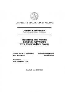
Fig. 1. Feature diagram examples.
An example of a feature diagram with different types of features is presented in Fig. 1a. Features f1 , f2 , f3 , and f4 are direct features of the concept C1 , while other features are its indirect features. Features f1 and f2 are mandatory alternative features. Feature f3 is an optional feature. Features f5 , f6 , and f7 are mandatory or-features. Feature f3 is open; ellipsis indicates that new features are expected in the existing group of or-features. A concept can be referenced as a feature in another or even in its own feature diagram, which is equivalent with the repetition of the whole feature diagram of the concept. Figure 1b presents the feature diagram of the concept C2 that refers to the concept C1 . Figure 1c presents the same diagram, but with the reference r expanded. To distinguish concept references from the rest of the features C1 ° r mark1 is being put after the name of a concept in a feature diagram, the ° reference. 1
For technical reasons, it will be presented as (R) in diagrams.
Additional information may be associated with concepts and features, which depends on the application, so it should be as configurable as possible.2 A concept reference may be associated with its own information as any other feature, but the information associated with the concept it references applies to it, too. 2.2
Constraints and Default Dependency Rules
Feature diagrams define the main constraints on feature combinations in concept instances. Since feature diagrams are represented as trees, in all but simplest cases it is impossible to express all the constraints solely by a feature diagram. Additional constraints are expressed in a list of constraints associated with the feature diagram. Also, a list of default dependency rules is associated with each feature diagram in order to specify which features should or should not appear together by default. Constraints and default dependency rules are specified by predicate logic expressions formed out of specific and parameterized names of concepts and features (see Sect. 2.3), and commonly used logical connectives (e.g., not ¬, and ∧ , or ∨ , xor ∨ , implication ⇒, and equivalence ⇔), commonly used quantifiers (e.g., universal quantifier ∀ and existential quantifier ∃), and parentheses. A feature name f in constraint or default dependency rule expressions stands for is in instance(f), a predicate which is true if f is embraced in the concept instance, and false otherwise. The intention of using predicate logic to express constraints and default dependency rules is to avoid ambiguities natural language is prone to. At this stage, the automated evaluation of the constraints and default dependency rules has not been considered, although that would certainly be useful. Feature names in expressions should be qualified to avoid name clashes, but since each expression is associated with a specific feature diagram, the domain and concept name are unnecessary. To avoid repeating long qualifications, as in A.B.C.x ∨ A.B.C.y, the common qualification may be introduced in front of the expression, e.g. A.B.C.(x ∨ y). Constraints A list of constraints associated with a feature diagram is a conjunction of the expressions it consists of. Thus, for a concept instance to be valid, all the constraints associated with the feature diagram must evaluate to true. Obviously, in case of a contradiction among the constraints, it is impossible to instantiate the concept. Constraints express mutual exclusions and requirements among features, i.e. they determine which features cannot appear together and which must appear together, respectively. A single constraint may express both mutual exclusions and requirements. Constraints have numerous equivalent forms, but they should be kept in the form which is as comprehensible as possible. Bearing this in mind, mutual 2
Such a configurability has been implemented in AmiEddi, a feature modeling editor (available at [19]), through so-called metamodel editor [21, 22].
exclusions may be expressed by connecting features with xor, while requirements may be expressed as implications or equivalences, depending on whether the requirement is bidirectional or not. As has been said, the main constraints are expressed directly in feature diagrams and thus need not be repeated in the information associated with them. However, sometimes it may be needed to change a feature diagram constraint to associated one, or vice versa. In a feature diagram, a mutual exclusion is expressed by alternative features. A requirement is expressed by a variable subfeature whose parent is also a variable feature: the subfeature requires its parent to be included. Also, a requirement may be expressed by or-features: at least one feature is required from a set of or-features. Default Dependency Rules A list of default dependency rules associated with a feature diagram is a disjunction of an implicit (not displayed) true and the expressions it consists of. The implicit true disjunct in a list of default dependency rules assures that it always evaluates to true. Default dependency rules determine which features should appear together by default. Default dependency rules are applied at the end of the process of concept instantiation if there are variable features left such that no explicit selection has been made among them. Which of these features will be included in the concept instance is decided according to the default dependency rules. 2.3
Parameterization in Feature Models
A parameterized name of a concept or feature has the form: p1 p2 . . . pn , where for each i ∈ [1, n] pi is either a parameter or specific string and where exists j ∈ [1, n] such that pj is a parameter. For each parameter, a set of possible strings that may be substituted for it has to be defined in its description. Parameters are introduced in brackets to distinguish them from specific strings. Name parameterization enables to reason more generally about concepts and features. An example of a parameterized name is Singular Form, where is a natural number. The specific names corresponding to this parameterized name are: Singular Form1, Singular Form2, etc.
[]
... 1
2
Fig. 2. Dealing with plural forms using a parameterized concept. Name parameterization is the only way to express constraints and default dependency rules about subfeatures of an open feature because their number
is unknown. Consider the feature diagram in Fig. 2 (ignoring the parameterizations of and for the moment). The feature is open; further direct variable subfeatures of the form , where is a natural number, are expected at it. The parameterized name is exactly how all these features may be referred to. A parameterized concept or feature is a concept or feature whose name is parameterized. Parameterized features may appear only in feature diagrams of parameterized concepts; otherwise, the feature model would be inconsistent since it would define a set of different feature diagrams for a single concept. For the same reason, parameterized concepts may not be referenced in feature diagrams of specific (i.e., non-parameterized) concepts. Figure 2 shows an example of a parameterized concept. The name is a plural form of .. Using a parameterized concept, we avoided drawing a separate feature diagram for each concept. 2.4
Representing Cardinality in Feature Models
Parameterized concepts are capable of representing UML style cardinalities represented by a comma separated list of the minimum..maximum cardinality pairs [7]. This may be achieved by a feature diagram in Fig. 3a with the following constraint which will assure the appropriate number of features according to the specified cardinality: _
((max6= ∗ ⇒
−+1 _
=1
∧ (max= ∗ ⇒
= ^
i ^
) ∧
k=1
))
k=1
[:..,...,..]
... Book 1
2
(R)
(R)
(a)
Authors:1..*
References:1..*
(b)
Fig. 3. Parameterized concept for representing cardinality (a) and an example of its application (b). The parameter is the plural form of the parameter . Note that parameters and are in fact doubly parameterized. This
is to enable the parameterization of the number of minimum..maximum cardinality pairs. The values allowed for both minimum and maximum cardinalities are natural numbers. Also, an additional value denoted by an asterisk is allowed for the maximum cardinality value meaning “many,” as in [7]. Zero cardinality is achieved by referencing the concept :..,. . . ,.. as an optional feature. This parameterized concept may be applied to any domain by including it in the feature model of the domain. Next, the set of the singular and plural forms of concept names corresponding to each other (representing possible values for and , respectively) has to be defined. Obviously, a feature model must include the concepts singular form concept names refer to. Finally, specific concept name and a set of minimum..maximum cardinality pairs should be substituted. An example is shown in Fig. 3b; a book has at least one author, and it may have zero (modeled by the optionality of References:1..*) or more references. 2.5
Concept Instantiation
An instance I of the concept C at time t is a configuration of C’s features which includes the C’s concept node and in which each feature whose parent is included in I obeys the following conditions: 1. All the mandatory features are included in I. 2. Each variable feature whose binding time is earlier than or equal to t is included or excluded in I according to the constraints of the feature diagram and those associated with it. If included, it becomes mandatory for I. 3. The rest of the features, i.e. the variable features whose binding time is later than t, may be included in I as variable features or excluded according to the constraints of the feature diagram and those associated with it. The constraints (both feature diagram and associated ones) on the included features may be changed as long as the set of concept instances available at later instantiation times is preserved or reduced. 4. The constraints associated with C’s feature diagram become associated with the I’s feature diagram. A concept instance is represented by a feature diagram derived from the feature diagram of the concept by showing only the features included in the concept instance. A concept instance is regarded further as a concept and as such may be considered for further instantiation at later instantiation times. During instantiation, a concept reference may appear in a concept instance as any other feature if it is not replaced by the diagram of the concept it references prior to instantiation.
3
Other Approaches to Feature Modeling
Feature modeling originates from Software Engineering Institute (SEI), where it was used in FODA method [3] developed there, which became a part of their
MBSE method. Recently, MBSE has been replaced by PLP approach [8, 9], which also employ feature modeling. An adapted version of FODA feature modeling is also a part of FORM method [4]. Since the publishing of FODA in 1990, several approaches have adopted FODA feature modeling, often in an adapted version [10, 1, 11]. Some work has been devoted primarily to extending feature modeling as such (with respect to UML) [12, 13], or even to formalize it [14]. Czarnecki-Eisenecker feature modeling [1] generalized FODA feature modeling notation and accepted a more general notion of a feature from ODM approach in which features are associated with particular domain practitioners and domain contexts [5], i.e. a feature is any concept instance property important to some of the stakeholders [1]. Such an understanding of a feature has been adopted also by FORM [4], a direct ancestor of FODA. Czarnecki-Eisenecker feature modeling is also more abstract than FODA or FORM feature modeling. In Czarnecki-Eisenecker feature modeling, relationships between a feature and its subfeatures don’t have any predefined semantics; the relationship is fully determined by the semantics of subfeatures. FORM feature modeling defines three types of relationships of a feature to its subfeature: composed-of, generalization/specialization, and implemented-by. Moreover, each feature is classified as a capability, operating environment, domain-technology, or implementation technique feature.3 According to their type, features are placed into one of the four layers feature diagrams are divided into. On the other hand, Matthias Riebisch argues against the classification of features according to FORM and proposes to classify features into functional, interface, and parameter features [15]. Therefore, it seems that it is better not to enforce such predefined feature categories in feature modeling. Concept instantiation with respect to feature binding time (see Sect. 2.5) is a generalization of concept instantiation as proposed in [1]. Compared to the set representation proposed in [1], even if the features are qualified as proposed in Sect. 2, feature diagrams are a more appropriate way to represent concept instances. Moreover, they enable to represent concept instantiation in time. The following sections discuss other solutions to referencing concepts, representing constraints and default dependency rules, and representing cardinalities. 3.1
Concept References
The problem of coping with complex feature diagrams has been recognized already in [1], where complex diagram are divided into a number of smaller diagrams, which then may be referred to in the main diagram by introducing their roots. Concept references, introduced by MPDfm feature modeling, are a logical extension of this idea. MPDfm feature modeling specifies how the information 3
This classification has been proposed already in [3], but since FODA was concerned with user visible features, it dealt only with (application) capabilities.
associated with the concept applies to its references and how it may be adapted to the needs of a particular reference. Concept references enable a concept to reference itself (directly or indirectly). This enables feature diagrams to be viewed as trees while being in conformance with the fact that feature diagrams in general are directed graphs. To refer to a concept or features unambiguously, a common dot convention is used in MPDfm feature modeling. A similar convention is used in FeatuRSEB [10], though without taking into account domain names, which may lead to ambiguities when talking about concepts and features from several domains. 3.2
Representing Constraints and Default Dependency Rules
In MPDfm, constraints and default dependency rules are expressed concisely as logical expressions. Logical expressions are capable of expressing both mutual exclusions and requirements among features. In fact, a single logical expression may encompass both types of the constraints. In FODA feature modeling, as well as in Czarnecki-Eisenecker feature modeling, constraints are expressed by explicitly stating which feature is mutually exclusive or requires which other feature. In [16], constraints are written in an adapted version of Object Constraint Language (OCL) used in Unified Modeling Language [7]. It is merely a matter of preference whether to use OCL syntax or traditional mathematical symbols for logical connectives (e.g., implies vs. ⇒). However, in [16], constraints are also accompanied by the information to be passed to the developer who instantiates the concepts that, for example, another feature has to be selected. This significantly reduces the readability of constraints. Better, such messages could be generated or a whole constraint could be passed instead. Incorporating messages to developers significantly reduces the readability of such constraints. Moreover, such messages to the developer may be generated or, even better, a whole constraint may be passed instead. The proposed form of expressing constraints and default dependency rules may be applied also to the constraints expressed directly by feature diagrams. This way, a whole feature diagram may be represented as a set of logical expressions. For the purpose of a graphical representation, a set of views of the feature diagram could be then defined. For each view, the relationships that should be shown would have to be specified with respect that the feature diagram should be a tree. The new constraints for the feature diagram could be then calculated to avoid duplicity (some of the constraints would be expressed in the feature diagram). In order to distinguish the primary relationships between the features expressed in a feature diagram from the constraints associated with it, one of the views could be denoted as primary. The need to represent feature diagrams in a graphically independent form has been identified also in [17]. The formalized feature modeling proposed in [14] actually relinquishes the feature diagrams completely, and with them the primary relationships between the features, too.
3.3
Representing Cardinalities
In the original Czarnecki-Eisenecker feature modeling, introducing feature cardinalities was strongly avoided arguing that since the only semantics of an edge is whether to assert a feature or not, cardinality would only mean to assert it several times, which is useless [1, p. 117]. Instead, to model the cardinality as a feature was recommended. In spite of this, a later work proposes to use the UML-style cardinalities with features [18]. Also, a generalized form of alternative and or-features is introduced in which the number of features which may be included is specified also as a cardinality (which does not contradict to the original Czarnecki-Eisenecker feature modeling).4 As has been demonstrated in Sect. 2.4, plural forms of the concepts and cardinality in general can be specified by parameterized concepts without compromising the principles of feature modeling. If preferred, UML cardinalities can be used instead, provided they are defined as a notational extension with respect to the parameterized concept.
4
A Feature Modeling Metamodel
The domain of feature modeling is understood here as a domain of the tools that support feature modeling as a central activity in software development. The feature modeling based methods, such as generative programming, FODA, FORM, FeatuRSEB, and feature modeling for multi-paradigm design, all have in common the central role of a feature model from which traceability links to other models are provided. The variability lies in the notations of feature modeling employed by different methods. The systems built in the domain would represent feature modeling CASE tools suitable for individual methods (possibly groups of methods). Based on the information presented in the previous sections, a metamodel of the feature modeling will be proposed in this section. The metamodel will be expressed using feature modeling itself in order to capture the variability of feature modeling notations and to describe the core concepts of feature modeling in a concise way. The purpose of this metamodel is to provide a basis both for further reasoning on feature modeling and for developing feature modeling tools. Therefore, the metamodel embraces features that express functionality, too. The concepts identified in the domain of feature modeling are: feature model, feature diagram, node, feature, partition, associated information, AI item, AI value, constraint, default dependency rule, and link. The model also includes the parameterized concept Plural Form introduced in Sect. 2.3, where . is a reference to one of the following concepts: Feature Diagram, Node, Feature, Link, Constraint, Default Dependency Rule, or AI Value. Dynamic binding of Plural Form features is assumed. In the rest 4
These extensions are implemented in Captain Feature (available at [20]), in which the whole feature modeling notation should be configurable through a metamodel represented by a feature model [23, 18], but its editing is not possible.
of the concepts, dynamic binding is indicated where applies; otherwise, static binding is assumed. 4.1
Feature Model and Feature Diagram
A feature model (Fig. 4) represents the model of a domain obtained by the application of feature modeling. It consists of a set of feature diagrams (Feature Diagram Set). and it may have a set of links to other modeling artifacts (Link Set). Feature diagrams in a feature model may be normalized [1] (Normalize), but this applies only to those feature modeling notations that embrace or-features.
Feature Model
New feature diagram Name
Description
Feature Diagrams Set
Link Set
Feature Diagrams(R) dynamic
Links(R) dynamic
Normalize
Delete feature diagram
Fig. 4. Feature Model concept. A feature diagram (Fig. 5) presents a featural description of a concept graphically. An additional constraint that applies to Feature Diagram is that a root may not be a concept reference: ¬Root.Node.Reference A feature diagram contains a set of nodes (Node Set) and a set of features (Feature Set). It may be represented by a directed tree (Tree). In this case, a feature diagram describes the features of a domain concept represented by its r An operation of adding a feature to a feature diagram root node (Root.Node°). represented as a tree (Tree.Add feature) should preserve the tree structure. A feature diagram may also be considered to be a connected directed graph. A set of constraints (Constraint Set) and default dependency rules (Default Dependency Rule Set) may be associated with a feature diagram, which is needed by some approaches to feature modeling. Also, a feature diagram may have a set of links to other modeling artifacts (Link Set). A feature diagram may be normalized (Normalize). 4.2
Node and Feature
Feature diagram nodes (Fig. 6) represent concepts in general sense (as explained in Sect. 2), which have they own names (Name), and concept reference nodes (Reference). It may have a set of links to other modeling artifacts (Link Set). Some approaches to feature modeling allow feature diagram nodes to be marked as open, which means that new direct features of a node are expected (Openness).
Feature Diagram Name Description Normalize
Node Set Nodes(R) dynamic Feature Set
Tree
Add feature
Add node
Graph
Remove node
Link Set
Constraint Set
Add feature Links(R) dynamic
Constraints(R)
Features(R) dynamic
dynamic
Root Remove feature
Default Dependency Rule Set Node(R) Default Dependency Rules(R) dynamic
Fig. 5. Feature Diagram concept. Node
Openness dynamic
Name Reference
Link Set Description
Node(R)
open
closed
Links(R) dynamic
Fig. 6. Node concept. A feature is a relationship between two nodes (Fig. 7). It describes the variability of a subfeature (Subfeature) with respect to its superfeature (Superfeature): the subfeature may be mandatory (mandatory), i.e. it must be included in a concept instance, or it may be optional (optional), i.e. it may be included in a concept instance. In some approaches to feature modeling, relationships between nodes are named (Name) or may have a type specified (Type). Also, a feature may have a set of links to other modeling artifacts (Link Set). 4.3
Partition
Features originating in one node may be divided into a set of disjunct partitions (Fig. 8) marked by arcs in feature diagrams. The features in a partition are presumed to be alternative, i.e. to have xor semantics (as in FODA). Some approaches (e.g., Czarnecki-Eisenecker notation and MPDfm) employ also orfeatures, so the features in a partition may be either alternative or or-features (Type). Other approaches (e.g. [18]) employ cardinality, which enables to specify the number of features (maximum and minimum) in a partition that may be
Feature Name
Link Set [Type]
Superfeature
Subfeature
Node(R)
Node(R)
mandatory
Links(R) dynamic
optional
Associated Information(R)
Partition(R)
Fig. 7. Feature concept. selected (Cardinality). Some approaches to feature modeling allow partitions to be marked as open (similarly to openness of a node in a feature diagram), which means that new direct features in a partition are expected (Openness).
Partition
Type
Cardinality
Openness
dynamic
dynamic
alternative
or
min
max
open
closed
Fig. 8. Partition concept.
4.4
Associated Information and Related Concepts
Different approaches to feature modeling, and different applications of it, too, require different information to be associated with features. The concept of associated information (Fig. 9) captures this demand by a fully configurable set of r items associated information consists of (AI Items°).
Associated Information
AI Items(R)
Add item
Remove item
Fig. 9. Associated Information concept. An associated information item (Fig. 10a) applicability may depend on the optionality of a feature with which it is associated (Applicability). There are two kinds of an associated information item: textually expressed ones (Textual) and those represented by a value selected from the extensible set of available values (Selectable). The concept of an associated information value (Fig. 10b) represents such a value.
AI Item Applicability Selectable
Textual Text
Value
AI Values(R)
AI Value dynamic
Remove value Add value
common features
variable features
(a)
Name
Description
(b)
Fig. 10. AI Item (a) and AI Value (b) concepts. 4.5
Constraint and Default Dependency Rule
Constraints (Fig. 11a) express mutual exclusions and requirements among features beside those specified by the feature diagram. They may be specified either as logical expressions (Logical expression), textually (Textual), or in a FODAlike form (see Sect. 3.2).
Constraint
Logical expression
Textual
Deafult dependency rule FODA-like
Logical expression
(a)
Textual
(b)
Fig. 11. Constraint (a) and Default Dependency Rule (b) concepts. Default dependency rules (Fig. 11b) determine which features should appear together by default in concept instances. They may be specified either as logical expressions (Logical expression) or textually (Textual). 4.6
Link
A link (Fig. 12) enables to connect a feature model or its parts to its own nodes and features, or to other models. These models include feature models, in which case a link may be more specific and point to a feature diagram in that model, or a node or feature in that diagram. An additional constraint that applies to Link concept is that a link may not lead to a node and feature simultaneously: Node ∨ Feature
5
Conclusions and Further Research
This paper brings several improvements into feature modeling. Concept instantiation is defined with respect to instantiation time with concept instances represented by feature diagrams. Parameterization in feature models enables to reason
Link dynamic File
Feature Diagram(R)
Node(R)
Feature(R)
Fig. 12. Link concept. more generally about concepts and features and to express constraints and default dependency rules about subfeatures of an open feature. Constraints and default dependency rules are represented by logical expressions. Concept references enable to deal with complex feature models. A dot convention enables referring to concepts and features unambiguously. A parameterized concept which enables to represent cardinality in feature modeling is introduced. Other approaches to feature modeling have been evaluated and compared with feature modeling for multi-paradigm design. Based on this analysis, a feature modeling metamodel has been proposed. The metamodel shows how the commonalities and variabilities of the domain of feature modeling may be modeled by feature modeling itself. This metamodel may serve both for further reasoning on feature modeling and as a basis for developing feature modeling tools. Further research topics include enhancing parameterization in feature modeling with respect to binding time/mode and expressing feature models fully in the form of constraints (as logical expressions) with defined primary constraints that are to be presented visually (in feature diagrams). Acknowledgements The work was partially supported by Slovak Science Grant Agency VEGA, project No. 1/0162/03.
References [1] Czarnecki, K., Eisenecker, U.W.: Generative Programing: Principles, Techniques, and Tools. Addison-Wesley (2000) [2] Coplien, J. O.: Multi-Paradigm Design for C++. Addison-Wesley (1999) [3] Kang, K.C., et al.: Feature-oriented domain analysis (FODA): A feasibility study. Technical Report CMU/SEI-90-TR-21, Software Engineering Institute, Carnegie Mellon University, Pittsburgh, USA (1990). [4] Kang, K.C., Kim, S., Lee, J., Kim, K., Shin, E., Huh, M.: FORM: A featureoriented reuse method with domain-specific reference architectures. Annals of Software Engineering 5 (1998) 143–168 [5] Simos, M.A.: Organization domain modeling (ODM): Formalizing the core domain modeling life cycle. In: Proc. of the 1995 Symposium on Software reusability, Seattle, Washington, United States, ACM Press (1995) 196–205 [6] Vrani´c, V.: Feature modeling based transformational analysis in multi-paradigm design. Submitted to Computers and Informatics (CAI), December 2003. [7] Object Management Group: OMG unified modeling language specification, version 1.5 (2003). [8] Chastek, G., et al.: Product line analysis: A practical introduction. Technical Report CMU/SEI-2001-TR-001, Software Engineering Institute, Carnegie Mellon University, Pittsburgh, USA (2001).
[9] Software Engineering Institute, Carnegie Mellon University: A framework for software product line practice — version 3.0. http://www.sei.cmu.edu/plp/ framework.html. Last accessed in June 2004. [10] Griss, M.L., et al.: Integrating feature modeling with the RSEB. In Devanbu, P., Poulin, J., eds.: Proc. of 5th International Conference on Software Reuse, Vicoria, B.C., Canada, IEEE Computer Society Press (1998) 76–85 [11] Geyer, L.: Feature modelling using design spaces. In: Proc. of the 1st German Product Line Workshop (1. Deutscher Software-Produktlinien Workshop, DSPL-1), Kaiserslautern, Germany, IESE (2000) [12] Riebisch, M., et al.: Extending feature diagrams with UML multiplicities. In: Proc. of the 6th Conference on Integrated Design and Process Technology (IDPT 2002), Pasadena, California, USA, Society for Design and Process Science (2002). [13] Clauβ, M.: Modeling variability with UML. In: Proc. of Net.ObjectDays 2001, Young Researchers Workshop on Generative and Component-Based Software Engineering, Erfurt, Germany, tranSIT (2001) 226–230 [14] Jia, Y., Gu, Y.: The representation of component semantics: A feature-oriented approach. In Crnkovi´c, I., Larsson, S., Stafford, J., eds.: Proc. of the Workshop on Component-based Software Engineering: Composing Systems From Components (a part of 9th IEEE Conference and Workshops on Engineering of ComputerBased Systems), Lund, Sweden (2002). [15] Riebisch, M.: Towards a more precise definition of feature models. In M. Riebisch, J. O. Coplien, D.S., ed.: Modelling Variability for Object-Oriented Product Lines, Norderstedt, BookOnDemand Publ. Co. (2003) 64–76 [16] Streitferdt, D., et al.: Details of formalized relations in feature models using OCL. In: Proc. of the 10th IEEE Symposium and Workshops on Engineering of Computer-Based Systems (ECBS’03), Pasadena, California, USA, IEEE Computer Society (2003) 297–304 [17] Lee, K., et al.: Concepts and guidelines of feature modeling for product line software engineering. In Gacek, C., ed.: Proc. of 7th International Conference (ICSR-7). LNCS 2319, Austin, Texas, USA, Springer (2002) [18] Czarnecki, K., et al.: Generative programming for embedded software: An industrial experience report. In Batory, D., et al., eds.: Generative Programming and Component Engineering: ACM SIGPLAN/SIGSOFT Conference, GPCE 2002. LNCS 2487, Pittsburgh, PA, USA (2002) 156—172 [19] Czarnecki, K., Eisenecker, U.W.: Generative programming — methods, tools, and applications. http://www.generative-programming.org. Last accessed in March 2004. [20] Captain Feature: Project page. https://sourceforge.net/projects/ captainfeature. Last accessed in March 2004. [21] Blinn, F.: Entwurf und implementierung eines generators f¨ ur merkmalmetamodelle. Master’s thesis, Fachhochschule Zweibr¨ ucken, Fachbereich Informatik (2001) In German. Available at http://www.informatik.fh-kl.de/~eisenecker (last accessed in March 2004). [22] Czarnecki, K., et al.: Generative programing: Methods, techniques, and applications. Slides and notes of the tutorial given at Net.ObjectDays 2003 (2003) [23] Bednasch, T.: Konzept und implementierung eines konfigurierbaren metamodells f¨ ur die merkmalmodellierung. Master’s thesis, Fachhochschule Kaiserslautern, Standort Zweibr¨ ucken, Fachbereich Informatik (2002) In German. Available at http://www.informatik.fh-kl.de/~eisenecker (last accessed in March 2004).