INTRODUCTION. With emerging new research efforts in biotechnology and computer networks, we ... often sacrificing the degree of expressive power of the matchers. In this paper, ...... Lecture Notes in Computer Science (LNCS), Madison, WI.
Reconfigurable Content-based Router using Hardware-Accelerated Language Parser JAMES MOSCOLA and JOHN W. LOCKWOOD Washington University in St. Louis and YOUNG H. CHO Open Acceleration Systems Research
This paper presents a dense logic design for matching multiple regular expressions with a field programmable gate array (FPGA) at 10+ Gbps. It leverages on the design techniques that enforce the shortest critical path on most FPGA architectures while optimizing the circuit size. The architecture is capable of supporting a maximum throughput of 12.90 Gbps on a Xilinx Virtex 4 LX200 and its performance is linearly scalable with size. Additionally, this paper presents techniques for parsing data streams to provide semantic information for patterns found within a data stream. We illustrate how a content-based router can be implemented with our parsing techniques using an XML parser as an example. The content-based router presented was designed, implemented, and tested in a Xilinx Virtex XCV2000E FPGA on the FPX platform. It is capable of processing 32-bits of data per clock cycle and runs at 100 MHz. This allows the system to process and route XML messages at 3.2 Gbps. Categories and Subject Descriptors: C.3 [Special-Purpose and Application-Based Systems]: General Terms: Pattern Matching, Parser, Content-based Routing, XML Additional Key Words and Phrases: Parsing, Regular Expressions, Pattern Matching, Parser Hardware, Content-based Routing, XML
1.
INTRODUCTION
With emerging new research efforts in biotechnology and computer networks, we foresee the increased need for fast and flexible pattern matchers. Recently, there has been a lot of research into leveraging reconfigurable hardware technologies for obtaining compact and fast pattern matching engines. However, much of the previous work focused mainly on the performance and size of the pattern matcher; often sacrificing the degree of expressive power of the matchers. In this paper, we attempt to address this issue by introducing a fully scalable regular expression pattern matcher. This research was sponsored by the Air Force Research Laboratory, Air Force Materiel Command, USAF, under Contract number MDA972-03-9-0001. The views and conclusions contained herein are those of the authors and should not be interpreted as necessarily representing the official policies or endorsements, either expressed or implied, of AFRL or the U.S. Government. Permission to make digital/hard copy of all or part of this material without fee for personal or classroom use provided that the copies are not made or distributed for profit or commercial advantage, the ACM copyright/server notice, the title of the publication, and its date appear, and notice is given that copying is by permission of the ACM, Inc. To copy otherwise, to republish, to post on servers, or to redistribute to lists requires prior specific permission and/or a fee. c 2007 ACM 1084-4309/2007/0400-0001 $5.00
ACM Transactions on Design Automation of Electronic Systems, Vol. V, No. N, September 2007, Pages 1–25.
2
·
Moscola, Cho, Lockwood
Additionally, all of these pattern matchers simply determine if a given pattern is present in a packet without considering the context of the pattern in the data stream. Without contextual information, the identified information has limited use. Therefore, we present parsing techniques to enable a higher level of understanding of data streams. These techniques are then utilized in the design and implementation of a content-based router. 1.1
Contributions
This paper makes several contributions in the areas of high-speed pattern matching and parsing. In the area of pattern matching, we present a new high-speed architecture that is both scalable and capable of searching for regular expressions. In the area of parsing, we present a technique for mapping regular grammars directly onto FPGA hardware. Finally, we utilize these techniques to develop a content-based router that is capable of multi-gigabit speeds. 1.2
Overview
The paper is organized as follows. Section 2 discussed related work in the areas of high-speed pattern matching and hardware-accelerated parsing. Section 3 presents two prominent logic-based pattern matching architectures developed by the FPGA research community. This section also describes how these architectures can be combined to create a new scalable architecture for matching regular expression patterns. In section 4, we describe an architecture for parsing regular languages. Finally, section 5 describes how our pattern matching and parsing techniques were used to develop a content-based router. The paper concludes in section 6. 2.
RELATED WORK
This section discussed related work in the areas of hardware-accelerated pattern matching and parsing. 2.1
Hardware-Accelerated Pattern Matchers
In recent years, a great deal of work has been done in the field of high-speed hardware-accelerated pattern matchers. In 2001, Sidhu and Prasanna presented a method for mapping regular expressions into nondeterministic finite automata (NFA) that could then be mapped onto FPGA hardware [R. Sidhu and V. K. Prasanna 2001]. In [Franklin et al. 2002] Franklin et al. illustrated how this technique can be used to map the patterns found in the Snort [Roesch 1999] database onto an FPGA. An additional pattern matching architecture for Network Intrusion Detection Systems (NIDS) was presented by Cho in [Cho et al. 2002]. In [Moscola et al. 2003] regular expression patterns were converted into deterministic finite automata (DFA) and mapped onto an FPGA. In [Clark and Schimmel 2003], Clark and Schimmel introduced the idea of pre-decoding input characters into single bit lines to reduce the number of comparators required for matching patterns. Sourdis presented the idea of using a pipelined comparator for matching patterns in [Sourdis and Pnevmatikatos 2003]. In [Baker and Prasanna 2004], Baker presented an architecture where all string comparators are connected to a single pipeline of decoded characters. In other work, Baker combines a small microcontroller with a bit-split architecture to create a high-speed regular expression matcher with the ACM Transactions on Design Automation of Electronic Systems, Vol. V, No. N, September 2007.
Hardware-Accelerated Language Parser
·
3
flexibility to modify the pattern set on-the-fly [Baker and Hong-Jip Jung 2006]. Work by Bispo expanded on Sidhu’s work in [R. Sidhu and V. K. Prasanna 2001] by adding support for Perl-compatible regular expressions [Bispo et al. 2006]. 2.2
Hardware-Accelerated Parsers
Hardware-accelerated parsing has not been an extensively studied problem. However, there does exist a small amount of previous work. In [Ciressan et al. 2000; Cristian-Raul et al. 2001], hardware-based parsers were implemented using the Cocke-Younger-Kasami (CYK) algorithm . While these implementations do manage to decrease the O(n3 ) time complexity of the CYK algorithm down to O(n2 ), the space required by the algorithm remains unchanged at O(n2 ), where n is the length of the input string. Such a large space requirement makes the CYK algorithm unsuitable for network applications that need to maintain parsing information for millions of network flows simultaneously. Other previous work includes a hardware-based implementation of an Early parser [Koulouris et al. 1998]. Again, the space requirements for this table driven parsing algorithm make it unsuitable for network applications. More recently, work by Cho in [Cho and Mangione-Smith 2005] presents two architectures, one for an LL(1) parser and another for an LR(1) parser. Both architecture take an approach similar to their software counterparts using table lookups in conjunction with a stack to parse the input. 3.
HARDWARE-ACCELERATED PATTERN MATCHING
The regular expression pattern matching architecture presented in section 3.4 of this paper is the result of studying several fast FPGA based pattern matchers. These pattern matchers and their key concepts are described sections 3.1, 3.2 and 3.3. 3.1
Pre-decoded Character Bits
Common among many of the FPGA based pattern matchers is the idea of predecoding characters. Since the regular expression patterns contain a fixed set of characters, we can use a pre-decoder to efficiently reduce the amount of space required by the design [Clark and Schimmel 2003]. The decoder logic is an 8-bit input AND gate with inversion of the bits needed to identify each character. Each letter used in the pattern is decoded uniquely to assert a single bit. The conversion from 8-bits per character to a single bit per character significantly reduces the amount of logic and routing required by the design. Since there is a relatively small penalty for a large fanout in FPGA, the pre-decoders are used in most of the recent pattern matching architectures. 3.2
Pipelined Regular Expression Chain
The pipelined regular expression chain is a technique for mapping regular expressions into a hardware representation of an NFA as described in [R. Sidhu and V. K. Prasanna 2001]. It can be thought of as a pipeline of AND gates as shown in figure 1a. At each stage of the pipeline, the output is asserted when the decoded character bit and the output of the previous stage are both asserted. Such a chain is capable of detecting specified strings in data streams. For this method, each character of ACM Transactions on Design Automation of Electronic Systems, Vol. V, No. N, September 2007.
4
·
Moscola, Cho, Lockwood
the pattern requires a single AND gate followed by a D-flip flop (DFF). The elementary functional unit in most FPGAs consists of one 4-bit input look-up-table (LUT) followed by a DFF. Therefore, the number of functional units for the above method corresponds to the total number of characters in the pattern set. This fixed string matching architecture can easily be extended to recognize a richer set of patterns with functions such as not, or, one-or-none, one-or-more, and zero-or-more. These functions are represented as logic primitives in figure 1. One can instantiate combinations of these elementary logic templates to build a full set of regular expression detectors.
a b
b
a a
Regex = a.b
Regex = !a
Regex = a|b Regex = a?
(a) Sequential
(b) Not
(c) Or / One-or-None
Fig. 1.
3.3
a
Regex = a+ Regex = a* (d) One-or-More / Zero-or-More
Constructing regular expressions
Pipelined Character Grid
An architecture by Baker attempts to optimize the use of logic by buffering the pre-decoded characters into a pipelined grid structure [Baker and Prasanna 2004]. Given such a grid of decoded characters, one can detect string patterns by ANDing all the corresponding decoded bits from different stages of the pipeline as shown in figure 2. Therefore, the pattern length must be less than or equal to the length of the pipeline. Since similar patterns tend to reuse the decoded outputs, the size of the grid is relatively constant. Therefore, the DFF resource requirement for this method is proportional to the number of patterns instead of characters. Given four input LUTs, the number of LUTs for long patterns can be reduced to a quarter of the pipelined chain method. The pipelined character grid can also be scaled by widening the input width. Since patterns can begin at any given alignment, a duplicate copy of the character decoder must be instantiated for each input byte alignment. For each pattern, its corresponding AND gate that detects a pattern must be replicated for each alignment. Then the outputs of the gates need to be ORed together to detect a match. Due to logic reuse, this architecture tends to yield denser designs for a larger pattern set. However, this logic compression is enabled by sacrificing the ability to match regular expressions. ACM Transactions on Design Automation of Electronic Systems, Vol. V, No. N, September 2007.
Hardware-Accelerated Language Parser
·
5
Pattern 1: "abc" = a2 . b1 . c0
"abc"
data
Dec
a0
a1
a2
a3
a4
b0
b1
b2
b3
b4
c0
c1
c2
c3
c4
a b c
"cbc" Pattern 2: "cbc" = c2 . b1 . c0
Fig. 2.
3.4
Simple example of pattern matcher using pipelined character grid
Timed Segment Matching
In studying the above techniques, we discovered that we can merge ideas from both architectures to create an even more space efficient regular expression pattern matcher [Moscola et al. 2006b]. The new architecture consists of a pipeline of decoded characters in conjunction with primitives similar to those used by the regular expression chain. This technique allows efficient use of FPGA resources while still being scalable and capable of matching regular expressions. A pattern matcher in Baker’s pipelined character grid detects an entire pattern at one instance by simply connecting all the corresponding decoded bits to a single AND gate [Baker and Prasanna 2004]. While examining such a design, we saw the opportunity to compress the size of the pipeline by matching small segments of the pattern at a time. By matching small segments of a pattern on subsequent clock cycles, some of the pipeline stages are reused allowing the grid structure to be compressed. While formulating the general effect of this, we found that the change was equivalent to combining the pipelined chain with the character grid architecture. Another way to express the approach is to combine four consecutive characters from a pipelined regular expression chain into a single LUT/DFF pair. In order to accomplish this, incoming characters are buffered using a pipelined character grid whose registers are reused for each of the patterns in the pattern set. We refer to this matching method as Timed Segment Matching (TSM). In most FPGAs, a basic block consists of a 4-input look up table (LUT) followed by a D-flip flop (DFF) and other supporting discrete gates. The design with shortest critical path would be the one where each pipeline stage would consist of only one level of basic blocks. With such a design criterion, the string comparator to match an N character pattern with AND gates, as shown in figure 3a, takes a minimum dlog N e of Σi=1 4 d 4Ni e gates. Note that this number does not include the logic required by the decoded character pipeline. By connecting the AND gates in a tree-like structure, the minimum latency is dlog4 N e stages. In addition to pipelined stages of AND gates, one must consider detection latency to indicate where the pattern starts or ends. Since pattern lengths can vary in practice, detection signals of shorter patterns must be delayed by (S − 1) − u clock cycles, where S is the number ACM Transactions on Design Automation of Electronic Systems, Vol. V, No. N, September 2007.
6
·
Moscola, Cho, Lockwood
data
decoder
a0
a1
a2
a3
a4
a5
a6
a7
a8
a9
b0
b1
b2
b3
b4
b5
b6
b7
b8
b9
c0
c1
c2
c3
c4
c5
c6
c7
c8
c9
Pipelined Character Grid
a9 a8 a7 a6 b5 b4 b3 c2 c1 c0
(a)
unused unused
(b)
a7 a6 a5 a4
Z AND unused
b4 b3 b2
c2 c1 c0
Z TS
Fig. 3. Fast FPGA pattern matchers for “aaaabbbccc” using pipelined character grid; (a) ZAN D uses AND gate matching and (b) ZT S uses timed segment matching method.
of stages in the longest pattern in the patten set and u is the number of stages in the short pattern of interest. This delay ensures that patterns are detected in the order in which they appear in the data stream and that short patterns cannot indicate a match prior to longer patterns that preceded them in the data stream. On the other hand, the logic architecture for the TSM method is simpler. The TSM architecture starts with a character pipeline similar to the one used in the pipelined character grid architecture. String comparators, similar to the regular expression chains in Sidhu’s architecture, are used to detect each pattern in the pattern set (figure 3b). However, unlike Sidhu’s architecture, the TSM architecture utilizes the character pipeline to buffer characters so that multiple characters can be matched by each AND gate. This allows more efficient use of logic resources. String comparators, like the one shown in figure 3b are generated by chaining together enough 4-input AND gates for the pattern of interest. The first AND gate in the chain is used to match the first four characters of the pattern. Subsequent AND gates in the chain only match 3 characters each since they must also include the result of the previous AND gate. Pseudocode for generating a string comparator for the TSM architecture is shown in figure 4. Matching an N character pattern using the TSM method yields a minimum of d N 3−1 e logic blocks with a latency that is directly proportional to the length of the dlog N e string. Through simple analytical observations, we find that Σi=1 4 d 4Ni e ≥ d N 3−1 e for N > 0. This indicates that the logic requirements for string comparators in our TSM architecture are less than or equal to logic requirements of string comparators in the pipelined character grid. More interesting, is that this is achieved while simultaneously creating an architecture that is capable of matching both strings and regular expression patterns. Another positive consequence of this method is that ACM Transactions on Design Automation of Electronic Systems, Vol. V, No. N, September 2007.
Hardware-Accelerated Language Parser
Fig. 4.
·
7
Pseudocode to generate a string comparator for the TSM architecture
information about a match is carried through the pipeline allowing the architecture to keep track of partial matches as they occur. This allows the TSM architecture to indicate that a match has occurred immediately after the last character of a pattern enters the pipeline, regardless of the length of the pattern. 3.4.1 Regular Expression Pattern Detection. Simple AND gate based detection requires a pipelined character grid where the number of pipeline stages is greater than or equal to the longest pattern. Since regular expressions can represent patterns that are infinitely long, it is impossible for the simple AND gate matcher and character grid to match all regular expressions. However, TSM modifies the detection method by adding a structure similar to pipelined regular expression chain. Given such a pattern matching structure, we are able to adapt the primitives for the pipelined regular expression chain for use in the TSM architecture. We illustrate the basic regular expression operations through examples shown in figure 5. The regular expression operations (e.g. zero-or-more) are shown in the shaded regions. The operations are shown as part of larger patterns to better illustrate how they are used. Both the zero-or-more operation (figure 5a) and the one-or-more operation (figure 5b) require a feedback path that allows the chain to iteratively match repeating substrings. Additionally, these two operations require that additional registers be placed in that feedback path. The additional registers ensure that the pipelined character grid has enough time to receive the characters required for the next iteration of the regular expression operation. Note that the total number of registers required in the feedback path is equal to the number of characters involved in the given regular expression operation. For example, in figure 5a the regular expression “aaaa(abc)*ccc” contains the zero-or-more operation. The number of characters included in the zero-or-more operation is three. This means that the total number ACM Transactions on Design Automation of Electronic Systems, Vol. V, No. N, September 2007.
8
·
Moscola, Cho, Lockwood
a5 a4 a3 a2
c2 c1 c0
z0
a4 b3 c2
a6 a5 a4 a3
a3 b2
a) z 0 = aaaa(abc)*ccc
a5 a4 a3 a2
c2 c1 c0
z1
b) z 1 = aaaa(ab)+ccc
a4 b3 c2
c2 c1 c0
a5 a4 a3 a2 z2
c2 c1 c0
a5 b4 c3 d2
z3
d) z 3 = (aaaa | abcd)ccc
c) z 2 = aaaa(abc)?ccc
Fig. 5. Regular expression operations in the timed segment matching architecture of registers required in the feedback path is also three. The regular expression operation in figure 5c is the one-or-none operation. This operation does not include a feedback loop, but it does require additional registers similar to the zero-or-more and one-or-more operations. Again, the number of additional registers required is equal to the number of characters included in the regular expression operation. The final operation show in figure 5d, the alternation operation, is the simplest of the regular expression operations. It requires the addition of only a single OR gate to the chain. No additional delay registers are required. Accordingly, it is easy to see how more complex regular expression can be constructed using the basic components for each of the regular expression operations. An example using both the zero-or-more operation and the alternation operation is shown in figure 6. Notice that the different size substrings in the alternation operation require a different number of delay registers. Thus an extra DFF is inserted at the input of the larger substring. a5 a4 a3 a2
a3 b2 c1
c2 c1 c0
b2 a1
z0
z 0 = aaaa(abc | ba)*ccc
Fig. 6.
TSM example for “aaaa(abc|ba)*ccc”
3.4.2 Scalable Architecture. Our TSM architecture can also be scaled while still maintaining its small size and the ability to scan for regular expression patterns. First, the character grid pipeline must be duplicated for each byte of the input width to provide decoded bits for every alignment, as shown in figure 7. Then the pipelined regular expression chains are constructed for each alignment. Although there are specific techniques to handle different regular expressions, we focus on ACM Transactions on Design Automation of Electronic Systems, Vol. V, No. N, September 2007.
Hardware-Accelerated Language Parser
·
9
the architecture for zero-or-more. Once its concept is understood, one can easily elaborate to build circuits for other operations (e.g. “a+” is equivalent to “aa*”).
data33
data2
data1
data0
decoder
decoder
decoder
decoder
a003
a113
a223
a333
a443
a553
a663
a773
a883
a993
b003
b113
b223
b333
b443
b553
b663
b773
b883
b993
c003
c113
c223
c333
c443
c553
c663
c773
c883
c993
a002
a112
a222
a332
a442
a552
a662
a772
a882
a992
b002
b112
b222
b332
b442
b552
b662
b772
b882
b992
c002
c112
c222
c332
c442
c552
c662
c772
c882
c992
a001
a111
a221
a331
a441
a551
a661
a771
a881
a991
b001
b111
b221
b331
b441
b551
b661
b771
b881
b991
c001
c111
c221
c331
c441
c551
c661
c771
c881
c991
a000
a110
a220
a330
a440
a550
a660
a770
a880
a990
b000
b110
b220
b330
b440
b550
b660
b770
b880
b990
c000
c110
c220
c330
c440
c550
c660
c770
c880
c990
Scaled Pipelined Character Grid
Fig. 7.
Wide pipeline grid for 4× scaled architecture
For a fixed string, the matching circuitry at each byte offset can be treated as an independent engine until they are ORed together at the end. However, the logic design complexity can grow rapidly when one attempts to scale regular expressions. This is because expressions that immediately follow alternation, one-or-none, oneor-more, or zero-or-more operations may start at multiple alignments. When the matchers are instantiated for all possible alignments, the entire circuitry can become exponentially large. Fortunately, we find that most of the instantiations turn out to be duplicated logic which can be combined and reused. To clearly understand the design process, we present a couple examples of the zero-or-more regular expression operation on a 4-byte input datapath. Four copies of the character grid are instantiated as shown in figure 7. The pre-decoded characters bits from these grids are then used by the pattern matching pipelines. Construction of a scaled chain works in a similar fashion to that of the single character wide version, by concatenating AND gates together (or regular expression primitives as shown in previous sections). The location of the character grid from which to retrieve the character works similarly to the single character wide version. However, in the scaled version, four characters advance through the character grid on each clock cycle. This means that if the scaled chain is currently examining the data2 position of stage 0 in the scaled pipeline grid, on the next clock cycle it must examine the data1 position of stage 1. This ensure that all characters get examined while processing a data stream. The simplest example of a scaled regular expression pattern matcher in our TSM architecture occurs when the regular expression operation includes same number of characters as the width of the input. In the example in figure 8a, notice that the zero-or-more regular expression operation (“*”) is operating on the four character string “bbbb”. In this case, the substring in the “*” operation is the same length as the width of the data input. Since any number of iterations of the “*” operation ACM Transactions on Design Automation of Electronic Systems, Vol. V, No. N, September 2007.
10 a 10 a 03 a 02
·
Moscola, Cho, Lockwood a 11 a 10 a 03
a 12 a 11 a 10
a 13 a 12 a 11
b11 b10 b03 b02
b12 b11 b10 b03
b13 b12 b11 b10
b20 b13 b12 b11
c 11 c 10 c 03
c 12 c 11 c 10
c 13 c 12 c 11
c 20 c 13 c 12
X X = aaa(bbbb)*ccc
a 13 a 12 a 11
a 12 a 11 a 10
a 11 a 10 a 03
a 10 a 03 a 02
b20
b13
b12
b11
c 20 c 13 c 12
c 13 c 12 c 11
c 12 c 11 c 10
c 11 c 10 c 03
Y Y = aaa(b)*ccc
Fig. 8. Examples of the zero-or-more regular expression operation in the scaled TSM architecture do not change the alignment of the immediately following substring “ccc”, the pattern matchers do not cross over to the other parallel matchers. In the example in figure 8b, the “*” is operating on the single character string “b”. In this case, the substring in the “*” operation is a single character. Therefore, every iteration of “b” would change the expected alignment for the “ccc” substring. As a result, every matcher is connected to its adjacent matcher. The above examples are regular expressions that are less than or equal to the width of the pipeline. However, our architecture is not restrictive. For substrings that are greater than the width of the pipeline, the substring can simply be broken down into smaller substrings while still applying the rules described in the previous sections. The example in figure 9 shows the iterative loop required for a regular expression operation that is larger than the pipeline width.
a 11 b10 b03 a 02
Fig. 9.
c 11 d10 d03 c 02
TSM architecture for ...“(abbacddc)*”...
ACM Transactions on Design Automation of Electronic Systems, Vol. V, No. N, September 2007.
·
Hardware-Accelerated Language Parser
3.5
11
Implementation
Using an automatic VHDL generator, we generated hardware for five of the pattern matching architectures described in this paper. The architectures implemented in this section include the 8-bit regular expression chain1 , the 8-bit and 32-bit pipelined character grid2 , and the 8-bit and 32-bit version of timed segment matcher architectures. To evaluate the five architectures, each was generated with five different pattern sets. The pattern sets range in size from 300 bytes to 3000 bytes. Additionally, we generated architectures that scan for full regular expressions using the 8-bit regular expression chain, and the 8-bit and 32-bit timed segment matcher architectures. The regular expressions were randomly generated in the form of “abcd(efgh)*ij”. Because the 8-bit and 32-bit pipelined character grid architectures don’t support regular expressions, no regular expression hardware was generated for those architectures. 3.5.1 Area and Performance. The hardware for each pattern set was synthesized and placed and routed on the Xilinx Virtex 4 LX200 -11 chips. For synthesis, we used Synplicity’s Synplify Pro v8.1. Placing and routing was completed using version 7.1 of the Xilinx back-end tools. Tables I and II, show the complete results for all the different architectures for each of the pattern sets we implemented. 8-bit Input (1 Character Wide) Regex Chain
Pipelined Grid
TSM
# of Chars
Freq MHz
TP Gbps
LUTs
LUTs /Byte
DFFs
Freq MHz
TP Gbps
LUTs
LUTs /Byte
DFFs
Freq MHz
TP Gbps
LUTs
LUTs /Byte
DFFs
300
436
3.49
319
1.06
471
438
3.50
172
0.57
730
432
3.46
168
0.56
600
600
433
3.46
572
0.95
747
399
3.19
266
0.44
1032
429
3.43
290
0.48
864
1200
441
3.53
1016
0.85
1212
436
3.49
422
0.35
1508
430
3.44
504
0.42
1289
2100
426
3.41
1672
0.80
1886
403
3.22
684
0.33
2197
435
3.48
856
0.41
1921
3000
411
3.29
2287
0.76
2503
420
3.36
931
0.31
2818
432
3.46
1202
0.40
2497
Table I. Device utilization for pipelined regular expression chain and pipelined character grid architectures
32-bit Input (4 Characters Wide) Pipelined Grid # of Chars
Freq MHz
TP Gbps
300
398
600
DFFs
Freq MHz
TP Gbps
LUTs
LUTs
LUTs /Byte
12.74
586
DFFs
1.95
1609
403
12.90
542
1.81
382
12.21
1153
913
1.52
2292
391
12.52
942
1.57
1200
368
1731
11.76
1511
1.26
3426
395
12.64
1676
1.40
2100
2766
377
12.05
2433
1.16
5049
374
11.98
2773
1.32
3000
4315
359
11.48
3372
1.12
6576
384
12.29
3832
1.28
5831
Table II. 1 Implemented 2 Implemented
TSM
LUTs /Byte
Device utilization for the architectures
as described by Sidhu [R. Sidhu and V. K. Prasanna 2001] as described by Baker [Baker and Prasanna 2004]
ACM Transactions on Design Automation of Electronic Systems, Vol. V, No. N, September 2007.
12
·
Moscola, Cho, Lockwood
As with the regular expression chain and pipelined character grid, our TSM architecture allows for very high clock frequencies. Both the 8-bit and 32-bit TSM architectures are capable of running at similar clock frequencies to those of the equivalent size chain or pipelined grid architectures. These high clock frequencies translate to bandwidths of up to 3.46 Gbps for the 8-bit architecture and 12.90 Gbps for the 32-bit architecture. It is worth noting that as the size of pattern sets increase, the clock frequency for all of the different architectures decreases slightly. This decrease in frequency is attributed to the increasing fanout of the decoded character bits as the size of the pattern set increases.
4500 4000
Number of LUTs
3500 3000 2500 2000 1500 1000 500 0 300
800
8-bit chain
Fig. 10.
1300 1800 Number of Pattern Bytes 8-bit pipeline
8-bit TSM
2300
32-bit pipeline
2800
32-bit TSM
LUTs vs. Number of Pattern Bytes
Including all of the decoder logic, the 8-bit TSM architecture utilizes only 0.40 LUTs/byte of the pattern for the 3000 byte pattern set. This is almost half the size of the regular expression chain architecture which requires 0.76 LUTs/byte for the same pattern set. The 8-bit pipelined character grid is slightly smaller than the TSM architecture, requiring only 0.31 LUTs/byte. The 32-bit TSM architecture and the 32-bit pipelined character grid are also similar in size requiring 1.28 LUTs/byte and 1.12 LUTs/byte respectively. The graph in figure 10 shows the number of LUTs required by each of the different architectures. The graph shows that the LUT resource requirement for the 8-bit regular expression chain is significantly larger than either of the other two 8-bit architectures. The 8-bit TSM architecture, while slightly larger than the 8-bit pipelined character grid, manages to stay close in size even with the added ability to do regular expression pattern matching. The number of LUTs/byte achieved by all of the architectures decreases as the size of the pattern set increases. This is because as the size of the pattern set increases, all of the decoder logic required by the architectures becomes a smaller and smaller percentage of the overall logic required. This means that the number ACM Transactions on Design Automation of Electronic Systems, Vol. V, No. N, September 2007.
Hardware-Accelerated Language Parser
·
13
2.50
LUTs per Byte
2.00
1.50
1.00
0.50
0.00 300
800
8-bit chain
Fig. 11.
1300 1800 Number of Pattern Bytes 8-bit pipeline
8-bit TSM
2300
32-bit pipeline
2800
32-bit TSM
LUTs/Byte vs. Number of Pattern Bytes
7000 6000
Number of DFFs
5000 4000 3000 2000 1000 0 300
800
8-bit chain
Fig. 12.
1300 1800 Number of Pattern Bytes 8-bit pipeline
8-bit TSM
2300
32-bit pipeline
2800
32-bit TSM
DFFs vs. Number of Pattern Bytes
of LUTs/byte for all of the architectures will asymptotically approach some value representing the minimum space requirements achievable by the architecture as shown in figure 11. The graph also shows that the lowest LUT resource utilization for the 8-bit and 32-bit TSM architectures are comparable to that of the 8-bit and 32-bit pipelined character grid architectures. The timed segment matching designs are the smallest architecture in terms if Dflip flop (DFF) utilization. For the largest pattern set, the 8-bit TSM architecture requires fewer DFFs than either of the other two 8-bit architectures. The 32-bit ACM Transactions on Design Automation of Electronic Systems, Vol. V, No. N, September 2007.
14
·
Moscola, Cho, Lockwood
TSM architecture also requires fewer DFFs than the 32-bit pipelined character grid as shown in figure 12. By calculating trend lines for both the number of LUTs and DFFs required for each architecture, it becomes clear that the DFFs are the limiting factor in the number of pattern bytes that can be programmed into the FPGA. Therefore, by having a smaller DFF resource requirement, the TSM architecture will be able to scan for larger pattern sets than both the regular expression chain and the pipelined character grid architecture. Using the trend line, the maximum number of strings that the Xilinx Virtex 4 LX200 FPGA can accommodate can be calculated to be approximately 31K patterns given that the patterns have an average length of 8 bytes. In addition to fixed strings, we generated regular expression pattern matchers using the 8-bit regular expression chain, and the 8-bit and 32-bit timed segment matcher architectures. Each architecture was generated to scan for 300 regular expression patterns in the form “abcd(efgh)*ij”. The results for the architectures are shown in table III. 8-bit Input (1 Character Wide)
32-bit Input (4 Characters Wide)
Regex Chain
Pipelined Grid
TSM
Pipelined Grid
TSM
LUTs
2913
N/A
1409
N/A
6676
DFFs
3087
N/A
1748
N/A
5395
Table III.
Device utilization when scanning for regular expressions
The results clearly show that 8-bit TSM architecture is much smaller than the 8-bit chain architecture in both LUT and DFF resource utilization when scanning for regular expressions. 4.
HARDWARE-ACCELERATED LANGUAGE PARSING
While pattern matching may be sufficient for applications such as network intrusion detection systems and spam filters, it may not powerful or expressive enough for many other applications. One such application is content-based routing. When a spam filter detects a false positive the end result may be that a valid email is incorrectly labeled as spam. However, false positives in a content-based router may have many undesirable affects, including improperly routed packets, excessively high latencies, packets that never reach their destinations, and networks that are bogged down by incorrectly multicasted packets. By incorporating a parser into the network we can achieve a higher level of understanding of streaming data. This higher level of understanding can reduce the number of false positives and help to alleviate the previously mentioned problems. The remainder of this section describes an architecture that can add semantic meaning to patterns that are found within streaming data. 4.1
Fast Regular Language Parser
Unlike other parsers which use a table to look up the next state of the parser, our regular language parser converts the rules of a regular grammar into a nondeterministic finite automaton (NFA) [Moscola et al. 2006c]. Representing the grammar ACM Transactions on Design Automation of Electronic Systems, Vol. V, No. N, September 2007.
Hardware-Accelerated Language Parser
·
15
as an NFA has two main benefits. First, it allows the grammar to be converted into a highly pipelined logic structure that can be mapped directly onto an FPGA. Using FPGA logic, as opposed to memory, allows for higher throughput. An NFA representation also allows the parser to exploit the parallelism of the FPGA by exploring all possible parsing paths in parallel. Additionally, an NFA generally has fewer states than its deterministic counterpart, thus allowing for a more compact representation.
For each terminal symbol Z FIRST [ Z ] ← {Z } repeat For each production X → Y1 ... Yk if Y1 ... Yk are all nullable (or if k=0) then nullable[ X ] ← true For each i from 1 to k , each j from i+1 to k if Y1 ... Yi −1 are all nullable (or if i=1) then FIRST [ X ] ← FIRST [ X ] ∪ FIRST [Yi ] if Yi +1 ... Yk are all nullable (or if i=k ) then FOLLOW [Yi ] ← FOLLOW [Yi ] ∪ FOLLOW [ X ] if Yi +1 ... Y j −1 are all nullable (or if i+1=j ) then FOLLOW [Yi ] ← FOLLOW [Yi ] ∪ FIRST [Y j ] until FIRST , FOLLOW and nullable no longer change
Fig. 13.
Algorithm for finding FIRST () and FOLLOW () sets from a production list
To model the grammar as an NFA, we use the well-known FIRST and FOLLOW set algorithms for predicative parsers [Aho et al. 1986]. These algorithms accept a grammar as input and output all the information necessary to construct an NFA. As defined in [Appel 1998], FIRST (α) is the set of all terminal symbols that can begin any string derived from α. FOLLOW (α) is defined as the set of terminal symbols that can immediately follow α. The FIRST and FOLLOW set algorithms are shown in figure 13. To illustrate these algorithms, we use the sample grammar shown in figure 14. The FIRST and FOLLOW sets for this grammar are displayed in a table in figure 15. Using the FIRST and FOLLOW sets, an NFA for the grammar can be constructed as follows. First, a state is created for each of the terminal symbols in the grammar, including the end-of-input symbol ($) which represents the accepting state. In the sample grammar, the terminal symbols are received, from, by and done. Then, for each terminal symbol, a transition is created to each of the terminal symbols in its FOLLOW set. Finally, the start states (multiple start states are possible) are identified. The FIRST set of the starting symbol identifies all of the terminal symbols that can start the grammar. The corresponding state for each ACM Transactions on Design Automation of Electronic Systems, Vol. V, No. N, September 2007.
16
·
Moscola, Cho, Lockwood
Fig. 14.
Sample regular grammar Fig. 15. FIRST and FOLLOW sets for symbols in the grammar
start
qr
primitve
received
received
received from
qf
qb
from
by
by q
done
d
done accept
q$ Fig. 16.
NFA for grammar in figure 14
Fig. 17. Hardware parser for grammar shown in figure 14
starting symbols is identified as a starting state. Figure 16 shows the NFA for the sample grammar in figure 14. A similar approach can be used to map the grammar directly into hardware. To build the hardware logic for the regular language parser, each terminal symbol in the grammar is represented using a simple primitive. The primitive, which can be seen in figure 17, consists of a single register and an AND gate. The inputs to each of the AND gates include the current state of the primitive (i.e. the output of the register) and a detection signal from a pattern matcher. When the pattern matcher detects a string which is representative of a terminal symbol in the grammar, it asserts a signal which is connected to the AND gate of the primitive for that symbol. The output of each AND gate represents a transition in the state of the grammar. Transitions are again determined from the FOLLOW sets of each of the terminal symbols in the grammar. The output of an AND gate for a terminal symbol is routed to the input of each of the primitives in its FOLLOW set. If the register of a primitive requires multiple inputs, an OR gate is used to combine the inputs into a single input for the primitive. As with the NFA model, the FIRST set of the ACM Transactions on Design Automation of Electronic Systems, Vol. V, No. N, September 2007.
Hardware-Accelerated Language Parser
·
17
starting symbol of the grammar provides the initial input to the parsing structure. This input can be asserted at the beginning of a data stream to initialize the parsing structure. While this technique does work for the grammar shown in figure 14, it may not work for all regular grammars. For example, adding the rule S → not received done to the grammar results in the addition of done into the FOLLOW set of received. This, in turn, results in the addition of a connection between the output of the received primitive and the input of the done primitive in figure 17. The addition of this connection results in a parsing structure that accepts invalid inputs. For example, the new parsing structure accepts the input received done, which is not defined by the grammar. To alleviate this problem, the original grammar can be modified by making each occurrence of a terminal symbol a unique symbol that is assigned its own primitive in the parsing structure. To illustrate, figure 18 shows the original grammar after adding the rule S → not received done and making each terminal symbol unique.
Fig. 18.
Sample grammar for a regular language
start
start
received2
received3
not1
from1
by1
received1
done1
done2
received z
from1
not 1
by1
received1
done z
accept Fig. 19. Hardware parser for grammar in figure 18
accept Fig. 20. Simplified parsing structure for grammar in figure 18
ACM Transactions on Design Automation of Electronic Systems, Vol. V, No. N, September 2007.
18
·
Moscola, Cho, Lockwood
The parsing structure that is generated for this new grammar using the FIRST and FOLLOW set technique described earlier is shown in figure 19. Note that there is now a primitive for each occurrence of each terminal symbol in the grammar and the structure only accepts the intended language. This structure can subsequently be minimized to decrease the number of primitives required for the parsing structure. For each terminal symbol X, if the input sets to Xi and Xj are equivalent, the primitives for Xi and Xj can be merged into a single primitive. This can be seen in figures 19 and 20 where received2 and received3 are merged into receivedz . Primitives for terminal symbols Xi and Xj can also be merged if the FOLLOW sets of Xi and Xj are equivalent. This is shown in figures 19 and 20 where done1 and done2 are merged into donez . Figure 20 shows the parsing structure for the grammar in figure 18 after being minimized. When combined with a pattern matcher, the hardware parser described in this section is capable of maintaining the state of a data stream. While doing so, the parser can also forward pattern information along with the state of the parsing structure for each pattern to a back-end for further processing. The back-end can utilize this information to take appropriate actions for the desired application. The following section describes how this technique can be used to develop intelligent network applications. 5.
CONTENT-BASED ROUTING MODULE
To help illustrate our hardware-based parsing technique and how it can be used in intelligent network applications, this section describes the implementation of a content-based router using the fast regular language parser presented in section 4.1 [Moscola et al. 2006a]. Our architecture for content-based routing can route packets with many different formats. Instead of routing packets based simply on strings that appear within the packet, our architecture parses the entire packet payload. Packet formats to be routed are specified using grammars. In this paper we illustrate how our architecture is configured and used to route XML packets. Since its introduction, XML has become the format of choice for exchanging information over networks. Additionally, we choose XML because there are many grammars already available for XML messages in the form of document type definitions (DTD).
card routekey name first last title phone
Fig. 21.
(routekey, name, title?, phone?)> (#PCDATA)> ((first, last) | (last, first))> (#PCDATA)> (#PCDATA)> (#PCDATA)> (#PCDATA)>
DTD for example implementation
Figure 21 shows an example DTD which represents a simple business card. It contains fields for a first name, a last name, a title, and a phone number. Additionally, the DTD contains a routekey field which indicates which field the router ACM Transactions on Design Automation of Electronic Systems, Vol. V, No. N, September 2007.
Hardware-Accelerated Language Parser
·
19
STRING [a-zA-Z0-9-]+ %% card: "" routekey name title phone "" routekey: "" route "" route: routefirst | routelast routefirst: "first" routelast: "last" name: "" nameN "" nameN: nameFL | nameLF nameFL: firstFL lastFL nameLF: lastLF firstLF firstFL: "" STRING "" lastFL: "" STRING "" lastLF: "" STRING "" firstLF: "" STRING "" title: "" STRING "" | ε phone: "" STRING "" | ε %%
Fig. 22.
Lex/Yacc style grammar
should use for routing. We will use this DTD throughout the remainder of this section to illustrate our content-based router architecture. Prior to generating the hardware to parse the DTD in figure 21, we first convert the DTD into a Lex/Yacc style grammar. The Lex/Yacc style grammar is shown in figure 22. This grammar is then passed into a custom compiler which automatically generates the VHDL required for the pattern matcher and the parsing structure. The layout of the main components of the architecture, including a pattern matcher, a parsing structure, and a routing module, is shown in figure 23.
data packets 32
Patterns
Grammar
...
...
Pattern Matcher
Fig. 23.
5.1
Pattern FIFO
Parsing Structure
Routing Module
data packets
Content-based router architecture
Parsing Structure
The parsing structure defines the semantics of patterns as they are detected by the pattern matcher. The hardware logic for the parsing structure is determined from the input grammar using the FOLLOW set algorithm as described in section ACM Transactions on Design Automation of Electronic Systems, Vol. V, No. N, September 2007.
20
·
Moscola, Cho, Lockwood
4.1. The FOLLOW set for our content-based router grammar is shown in figure 24. The resulting parsing structure for our content-based router implementation is illustrated in figure 25. Patterns
FOLLOW Set
first, last
first, last
1, 1
1, 1, 2, 2, ,
STRING
STRING
1, 1, 2, 2, ,
1
1
2
2
1, 2
, ,
,
Fig. 24.
FOLLOW sets for content-based router grammar
start of packet P6
P0
1
P7
P1
STRING1
P2
first
1
P13
P5
P21
P24
P16
STRING 2
P11
1
P23
STRING
P15
P10
P20
STRING
2
STRING1
P22
P14
P9
P4
P19
2
1
STRING 2
P8
P3
last
P18
P12
2
P17
2
P25
XML valid
Parsing Structure Fig. 25.
Diagram of parsing structure
ACM Transactions on Design Automation of Electronic Systems, Vol. V, No. N, September 2007.
Hardware-Accelerated Language Parser
·
21
The generated parsing structure processes packets one pattern at a time. At the start of a packet, the starting register (register P0 in figure 25) is set. As packets are processed, the parsing structure receives a signal from the pattern matcher for each pattern that is found. These signals allow the parsing structure to traverse through the grammar and maintain the semantics of the data stream. During processing, all signals from the pattern matcher are sent downstream to the routing module accompanied by the state of the parsing structure. The state of the parsing structure indicates where in the grammar each pattern is found. Knowing where in the grammar a pattern is found allows the routing module to make more intelligent decisions. To better understand this, consider that the parsing structure in figure 25 is searching for several instances of STRING. However, if the router is configured to route on a first name, only STRING values that occur at register P7 or P16 should affect the action that the router takes. Other occurrences of STRING, those at P10, P13, P20, and P23, should not affect the action taken by the content based router. Without parsing the entire data stream and maintaining the context of where each STRING value occurs, this behavior is not possible. 5.1.1 Validating XML Input. To avoid routing invalid or malformed XML messages, our content-based router validates all XML messages prior to routing them. As shown in figure 25, an XML valid signal is asserted when the parsing structure successfully traverses through the entire grammar. The XML valid signal is forwarded to the routing module which can subsequently take the appropriate routing action on the XML message. 5.2
Routing Module
The routing module, shown in figure 26, is responsible for modifying the IP header of each packet to route the packet to the appropriate destination. As packets enter the content-based router they are buffered in the routing module until the packet has been completely processed. Prior to routing any packet, the routing module verifies that the packet is the correct format. Most importantly, this entails validating the XML message. XML messages that do not strictly adhere to the grammar provided will not be rerouted by the module. Optionally, the module can also check for specific IP address and port ranges prior to routing. For our example implementation, we want to route packets based on the first character of either the first name or the last name specified in the XML message. The routekey value specifies which name to use for routing. A series of control signals received from the pattern matcher and the parsing module allow the routing module to route packets accordingly. These control signals are described below and can be seen in figure 26. The value routefirst is enabled by the parsing structure when register P2 is set and the pattern first is detected by the pattern matcher. This value indicates that the packet should be routed according to the first name in the XML message. Similarly, the value routelast is enabled when register P3 is set and the pattern last is detected. It indicates that the packet should be routed according to the last name in the XML message. These values stay enabled for the duration of the packet. The firstSTRING value is enabled by the parsing structure when either register ACM Transactions on Design Automation of Electronic Systems, Vol. V, No. N, September 2007.
22
·
Moscola, Cho, Lockwood data packets
output controller
32
data packets
Packet Buffer IP valid Port valid XML valid
reroute packet
routefirst firstSTRING routelast lastSTRING route character
D E Q
8
Routing Module Fig. 26.
dest. IP
route data Route Table
Diagram of routing module
P7 or register P16 are set and a STRING pattern is detected by the pattern matcher. Similarly, the lastSTRING value is enabled when either register P10 or P13 are set and a STRING pattern is detected. The firstSTRING and lastSTRING values are only valid for a single clock cycle. During this clock cycle, the first character of the STRING pattern (the route character) is forwarded to the routing module and stored. This value is then used to address a routing table which determines the next destination of the packet being processed. Once a packet has been fully processed, the output controller reads the packet from the packet buffer for output. If the packet contains a valid XML message (and optionally, IP address and port ranges), then the IP header is rewritten with the new destination address as it is output. 5.3
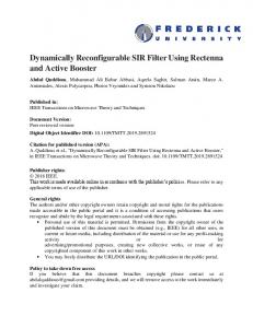
Implementation and Experimental Setup
The content-based router described in this paper was fully implemented and tested on the Xilinx Virtex XCV2000E FPGA on the FPX platform. The FPX was integrated into a Global Velocity GVS-1000 chassis. A photograph of an FPX and the GVS-1000 chassis is shown in figure 27. The GVS-1000 has two bidirectional gigabit interfaces for passing traffic into the FPX. To test our content-based router architecture, each of the gigabit interfaces on the GVS-1000 were connected to a different host machines. One machine was used to generate and send XML messages into the content-based router. The second machine was used as a receiver for routed messages. Since only two machines were used for our experiments, we routed XML messages to different ports on the receiving machine based on the message content. Both Ethereal and a small counter application were used to verify XML messages arrived at the correct destination port on the receiving machine. ACM Transactions on Design Automation of Electronic Systems, Vol. V, No. N, September 2007.
Hardware-Accelerated Language Parser
Fig. 27.
5.4
·
23
FPX and GVS-1000 chassis
Area and Performance
For this application our maximum clock frequency is limited to 100 MHz by the protocol processing infrastructure. At this speed our content-based router can achieve a maximum throughput of 3.2 Gbps. Without the protocol wrappers, the core of the content-based router architecture can achieve frequencies over 200 MHz. At this speed the content-based router can route XML data messages at over 6.4 Gbps. The content-based router requires 3751 slice flip flops, approximately 9% of the available flip flop resources. The architecture requires 3058 4-input LUTs, approximately 7% of the available LUT resources. The infrastructure for protocol processing alone requires 2623 slice flip flops and 2196 4-input LUTs. This is approximately 6% and 5% of the available flip flop and LUT resources respectively. The core of the content-based router (without the protocol processing infrastructure) requires approximately 1128 slice flip flops and 862 4-input LUTs. This is approximately 2.9% and 2.2% of the available flip flop and LUT resources respectively. Such a small space requirement for the core of the routing architecture means we can fit much larger and/or many more grammars on the FPGA. 6.
CONCLUSION
In this paper we described a new architecture for a scalable regular expression pattern matcher. By studying the advantages of the pipelined regular expression chain and the character grid architectures, we have created a novel pattern matching architecture. Several pattern matching architectures were implemented on a Xilinx Virtex 4 LX200 FPGA and compared. Our TSM architecture is capable of running at over 400 MHz and processing regular expression patterns at up to 12.90 Gbps. Additionally, we presented a parsing architecture that can be automatically generated from regular grammars. We illustrated how the regular language parser can be used to implement a content-based router. The content-based router was implemented and tested in the Xilinx Virtex XCV2000E FPGA on the FPX platform. The architecture was placed and routed at 100 MHz and can process XML messages at 3.2 Gbps. Without the infrastructure required for protocol processing, ACM Transactions on Design Automation of Electronic Systems, Vol. V, No. N, September 2007.
24
·
Moscola, Cho, Lockwood
the content-based router architecture is capable of running at over 200 MHz and processing XML messages at over 6.4 Gbps. REFERENCES Aho, A., Sethi, R., and Ullman, J. 1986. Compilers: Principles and Techniques and Tools. Addison-Wesley. Appel, A. W. 1998. Modern Compiler Implementation in Java. Cambridge University Press. Baker, Z. and Hong-Jip Jung, V. K. P. 2006. Regular Expression Software Deceleration for Intrusion Detection Systems. In Proceedings of International Conference on Field-Programmable Logic and Applications (FPL). Madrid, Spain. Baker, Z. K. and Prasanna, V. K. 2004. A Methodology for Synthesis of Efficient Intrusion Detection Systems on FPGAs. In IEEE Symposium on Field-Programmable Custom Computing Machines. IEEE, Napa Valley, CA. Bispo, J., Sourdis, I., Cardoso, J. M., and Vassiliadis, S. 2006. Regular Expression Matching for Reconfigurable Packet Inspection. In Proceedings of International Conference on Field Programmable Technology (FPT). Bangkok, Thailand. Cho, Y. H. and Mangione-Smith, W. H. 2005. High-Performance Context-Free Parser for Polymorphic Malware Detection. In Advanced Networking and Communications Hardware Workshop. Lecture Notes in Computer Science (LNCS), Madison, WI. Cho, Y. H., Navab, S., and Mangione-Smith, W. H. 2002. Specialized Hardware for Deep Network Packet Filtering. In 12th Conference on Field Programmable Logic and Applications. Springer-Verlag, Montpellier, France, 452–461. Ciressan, C., Sanchez, E., Rajman, M., and Chappelier, J.-C. 2000. An FPGA-Based Coprocessor for the Parsing of Context-Free Grammars. In Proceedings of IEEE Symposium on Field-Programmable Custom Computing Machines (FCCM). Napa, CA. Clark, C. R. and Schimmel, D. E. 2003. Efficient Reconfigurable Logic Circuits for Matching Complex Network Intrusion Detection Patterns. In International Conference on Field Programmable Logic and Applications (FPL). Lisbon, Portugal, 956–959. Cristian-Raul, C., Eduardo, S., and Martin, R. 2001. An FPGA-Based Syntactic Parser for Real-Life Unrestricted Context-Free Grammars. Technical Report No. 01/373 01/373, Swiss Federal Institute of Technology (EPFL), Lausanne (Switzerland). October. Franklin, R., Carver, D., and Hutchings, B. L. 2002. Assisting Network Intrusion Detection with Reconfigurable Hardware. In IEEE Symposium on Field-programmable Custom Computing Machines. IEEE, Napa Valley, CA. Koulouris, A., Koziris, N., Andronokos, T., Papakonstantinou, G., and Tsanakas, P. 1998. A Parallel Parsing VLSI Architecture for Arbitrary Context Free Grammars. In Proceedings of International Conference on Parallel and Distributed Systems (ICPADS). Tainan, Taiwan. Moscola, J., Cho, Y. H., and Lockwood, J. W. 2006a. A Reconfigurable Architecture for Multi-Gigabit Speed Content-Based Routing. In Proceedings of Hot Interconnects 14 (HotI). Stanford, CA, USA. Moscola, J., Cho, Y. H., and Lockwood, J. W. 2006b. Fast Semantic based Identification of Regular Expressions using Reconfigurable Devices. In submitted to IEEE Symposium on Field-Programmable Custom Computing Machines (FCCM). Napa, CA. Moscola, J., Cho, Y. H., and Lockwood, J. W. 2006c. Reconfigurable Context-Free Grammar based Data Processing Hardware with Error Recovery. In Proceedings of International Parallel & Distributed Processing Symposium (IPDPS/RAW). Rhodes Island, Greece. Moscola, J., Lockwood, J., Loui, R., and Pachos, M. 2003. Implementation of a ContentScanning Module for an Internet Firewall. In IEEE Symposium on Field-Programmable Custom Computing Machines. IEEE, Napa Valley, CA. R. Sidhu and V. K. Prasanna. 2001. Fast Regular Expression Matching using FPGAs. In IEEE Symposium on Field-Programmable Custom Computing Machines. IEEE, Napa Valley, CA. Roesch, M. 1999. Snort - Lightweight Intrusion Detection for Networks. In USENIX LISA 1999 conference. USENIX, http://www.snort.org/. ACM Transactions on Design Automation of Electronic Systems, Vol. V, No. N, September 2007.
Hardware-Accelerated Language Parser
·
25
Sourdis, I. and Pnevmatikatos, D. 2003. Fast, Large-Scale String Match for a 10Gbps FPGAbased Network Intrusion Detection System. In 13th Conference on Field Programmable Logic and Applications. Springer-Verlag, Lisbon, Portugal.
Received August 2006; March 2007; August 2007
ACM Transactions on Design Automation of Electronic Systems, Vol. V, No. N, September 2007.