The key innovation of the described Hardware-in-the-loop (HIL) simulator is the use of flexible and software reconfigurable signal-conditioning to establish ...
Contributed Paper: Reconfigurable Hardware-in-the-loop Simulator
Reconfigurable Hardwarein-the-loop Simulator Suguna Thanagasundram and Ross McMurran International Automotive Research Centre (IARC), University of Warwick, Coventry, UK
Executive Summary
The key innovation of the described Hardware-in-the-loop (HIL) simulator is the use of flexible and software reconfigurable signal-conditioning to establish connectivity between the HIL simulator and the prototype Electronic Controller Units (ECUs) in the Electronic Body System (EBS) of a vehicle. In the automotive industry, the electrical architecture of the car Alexandros evolves through many development phases and iterations. At Mouzakitis each design phase, changes are made in the software code Electrical Integration, Jaguar of the ECU and the hardware interface may also be changed Land Rover, Engineering Centre, from one phase to the next. The full functionality of the ECUs Coventry, UK is achieved only after several iterations.With the use of the software reconfigurable HIL simulator, interfacing the ECUs Christian Matthews during the development stage becomes easier. As the ECU add2, Staffordshire, UK connectors change or when new pins are added, all that is required is to change the signal conditioning interface of the Peter Jones HIL system while leaving all the other connections intact.The School of Engineering, University paper describes a flexible and software reconfigurable HIL of Warwick, Coventry, UK simulator in detail and the benefits it brings about in validating ECU functionality in the automotive industry.
Introduction A HIL simulator is used in the development and testing of embedded controllers in the Electronic Control Units (ECUs)1-2. Performing validation and verification of the functional specification of the ECUs in a traditional vehicle electrical development platform such as the yellowboard (a breadboard type of platform for testing electrical functionality) or in a prototype vehicle is costly both in time and money as static test benches having the actual wiring harness, loads and sensors are required. In the automotive industry, vehicle manufacturers commonly utilize HIL simulation systems to carry out automated testing to make an initial evaluation of the controllers and assessment of the performance of the full functionality of the prototype parts in the car prior to the building of whole vehicle3-4. The use of a HIL simulator to test and analyse automotive electronic control systems has been well documented by many researchers5-9. This paper presents a software reconfigurable simulator based on the latest HIL technologies. The discussed HIL simulator differs from the above mentioned HIL simulation platforms in that it is flexible and has signal conditioning which is reconfigurable by software. The need for such a flexible HIL simulator in
www.instmc.org.uk
the context of the research problem is first discussed. The flexible and software reconfigurable HIL simulator is then introduced and its system design is presented in detail.
Validating Functionality of an ECU An ECU, such as the engine management system in the Electronic Body Systems (EBS) of a car, can have as many as 140 pins to interface to the ‘real’ world. The ECUs are distributed throughout the vehicle and communicate with each other in the car through communication protocols such as Controller Area Network (CAN), Local Interconnect Network (LIN), Media Oriented System Transport (MOST) or the latest emerging protocol based on FlexRay technology. The main function of a HIL simulator is to emulate vehicle dynamics including the sensors and actuators in order for the physical ECU to think that it is part of the real vehicle. An ECU outputs an electrical signal either in the voltage or current form which is digitized through an Analogue-to-Digital Converter (ADC) by the data acquisition cards (I/O boards) in the HIL simulator. These signals are fed as control variables to the simulation models held in application software in the HIL simulator. Before the output signals from the physical ECU can be discretised into digital form by the ADC cards, they are suitably modified by the signal conditioning circuitry in the HIL simulator. The output signals from the ECUs are amplified or attenuated to a suitable voltage level in order to match the dynamic range of the 16-bit or 24-bit ADC cards used in the HIL simulator. This is done to match the range and resolution of the ADC cards. For instance typically in automotive systems, the output signals from an ECU have a voltage level at 14V. This has to be brought down to voltage levels of ± 10V input range typical of ADC and DAC I/O boards. Similarly, the output signals from the simulated components of the HIL simulator must be suitably amplified or attenuated to match the required input signal levels of the ECUs. In a similar fashion, the digital TTL (Transistor-Transistor Logic) signals and frequency modulated signals such as PWM signals are conditioned first by the signal conditioning circuitry prior being transmitted to and from the simulated and real components of the HIL simulator. Most simulators used in practice today have some form of signal conditioning interface in the HIL platform but most often this interface is fixed. If the hardware interface of an ECU changes, for example, if the pinout of the hardware connectors of an ECU changes by the addition or deletion of pins or existing pins change their position in the interface connectors, the ECU needs to be rewired to the wiring harness of the HIL simulator by the testing engineers. The wiring job may not look daunting if just one ECU connected to the HIL simulator is affected. In many automotive electrical testing facilities, whole array of ECUs are connected to the test rig to simulate the electrical system in a car on the CAN, LIN and MOST networks. Though all efforts are taken to keep the wiring job tidy, it is important to remember that as many as 50
Measurement + Control Vol 43/9 November 2010 • 273
Contributed Paper: Reconfigurable Hardware-in-the-loop Simulator ECUs can be connected to the test rig at the same time and each of them can have as many as 100 pinouts. Even if the pinout of just one ECU changes over time with the design iterations, a lot of effort and time is spent on redoing the rewiring as the task of tracing the affected wiring becomes very complicated. The reusability of the HIL simulator from one vehicle programme to another is limited. For example, take the case of a HIL simulator which has been originally designed to the specification to support 100 digital signals and 50 analogue ones. If there is a requirement to use this existing HIL simulator to support another vehicle programme which requires more analogue signal connectivity, it becomes impossible to use the existing HIL simulator. The architecture of the HIL simulator has to be physically changed by the addition of more ADC and DAC cards. In practice, it will be found that there will be some redundancy in the HIL simulator by the availability of some extra pins in the ADC and DAC cards which are unused, but often the signal conditioning of these modules will not be existent or the outputs from these cards will not be mapped out onto the test bench of HIL simulator. Often it is required to send back the HIL simulator to its source, to adapt it from vehicle programme to another. In such cases, manual changes are done by changing the jumper settings of the data acquisition cards or modifying the signal conditioning modules which are accessed through the backplane of the rack system of the HIL simulator. ADC and DAC cards are also added and removed as required and a change in the internal wiring in the HIL simulator also needs to be redone. It is costly and time consuming to implement these changes.
Reconfigurable HIL Simulator To address the weaknesses found in current existing HIL simulators, a flexible and highly software reconfigurable HIL simulator was designed and evaluated as a pilot study. The main objectives of setting
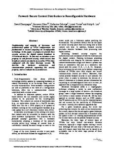
up this flexible HIL simulator is to alleviate the problems faced in the standard HIL simulator when the ECU pinout changes or when the HIL simulator is used from vehicle line to another. The HIL simulator consists of two fullsize HIL racks (up to 2m in height) and a testbench in the middle populated with the real prototype ECUs under test (see Figure 1). Each of the HIL racks hosts the processor, I/O boards, signal conditioning, electrical failure simulation units and a PSU acting as battery simulation for the ECUs.The main processors on each rack are interconnected via a Gigalink (1.25 Gbit/s) connection for high data speed transfers.The ECUs on the testbench are connected to the HIL servers through the wiring harness of the test bench. At the bottom of the rack is the real-time hardware.This consists of the real-time processor board running the simulation models and the various real-time I/O cards.The signals coming in and out of the real time hardware are unconditioned and connected to the signal conditioning module. Each signal conditioning modules has the flexibility of software configurability to manipulate the signal conditioning.
Signal conditioning which is reconfigurable by software The unique and novel innovation in this HIL simulator is the use of configurable signal conditioning. To connect any signal source to its required I/O card, prior signal conditioning is necessary. In the past, the signal conditioning configuration of I/O ports of the HIL simulator have been fixed and this has hampered progress in the testing procedure as there is a need to rebuild and redesign the interface circuit to meet the requirements of the ECU. This problem has been allayed with the reconfigurable HIL simulator as each of the channels can be configured individually under software control. The front end can be designed and customized for different kind of sensors and has the capability to support all feasible combinations
Figure 1: Reconfigurable HIL Simulator
274 • Measurement + Control Vol 43/9 November 2010
www.instmc.org.uk
Contributed Paper: Reconfigurable Hardware-in-the-loop Simulator of the I/O interface of the ECUs. Each channel can be configured according to its signal type, direction, bandwidth, gain and loading requirements. 1. �The direction of each channel can be configured as an input or output. 2. �The type of the signal can be specified as an analogue or digital. 3. �The reconfigurable HIL simulator can create the impedance that an ECU experiences. Load is introduced into the circuit to vary the impedance as seen by the ECU as this determines the amount of current drawn to and from it. The degree of loading is set internally in the HIL simulator by a variable load. The loading magnitudes of each of the channels can be configured individually by software. The impedance of each channel can be configured within a broad range of resistance values. 4. �The loading arrangement of each channel can be selected by the user. Each of the internal loads mentioned above can be pulled up to a supply rail or pulled down to ground or in the case of inputs, be placed between a differential pair of signals. 5. �The HIL simulator has the ability to support either internal or external loads. In certain scenarios, the real external load or actuators are connected to the simulator to represent more realistic loading arrangements. For instance, in this application, the real mirrors were attached to the simulator to sink and source more realistic currents from the simulator and to simulate more realistic impedance characteristics of the system. 6. �The digital input circuit has a configurable threshold detection capability and the output switching levels of each digital input signals can also be set to any of the fractional voltages of the high power rail. For example, if the channel uses Vext1 as the high power rail and Vext1 is tied to PSU1 providing the VBatt voltage, and in this
case, has been set to a constant Direct Current (DC) voltage of 12V, then the threshold detection voltage can be set to any of the fractional voltages of Vext1 like 6V, 3V or 2V. 7. �The gain of the analogue inputs and outputs can be defined to match any of the common ranges such as 0.5, 1, 5, 10, 50 and 100. The analogue output voltage from the real-time I/O hardware can be modified by one of two different gains as the required by the application. 8. �Analogue inputs can be conditioned using one of 3 preset filters. The user can choose between three first-order low pass filters, with different cutoff frequencies. This can help to remove unwanted noise, hence providing a higher quality signal before being discretised by the ADC boards. All these aspects can also be achieved in a typical HIL simulator by manual reconfiguration but the key difference of this HIL simulator is the ability to reconfigure the signal conditioning interface through an intuitive and user-friendly graphical software called HCU (HIL Configuration Utility). The signal conditioning interface circuits can be customized easily by setting the values in the HCU interface (see Figure 2). This allows one to quickly reach a certain architecture configuration and also modify it in a short time if required. An example of the easy configuration of an analogue input signal is shown. The implementation of the controller algorithm in the ECU becomes easier with a configurable simulator because changes in the specification of ECU functionality, followed by changes in the ECU hardware interface connectors, can be more easily accommodated, with changes in the wiring harness of the test rig that are easily manipulated at software level through the use of HCU.
Figure 2: Easy configuration of the signal conditioning through the HCU
www.instmc.org.uk
Measurement + Control Vol 43/9 November 2010 • 275
Contributed Paper: Reconfigurable Hardware-in-the-loop Simulator
The HIL Power Supply System Each signal conditioning module in the HIL simulator can be set to reference one of the three different external voltage sources (Vext1,Vext2 or Vext3) as the high power rail and one of two different 0V references (0V1 or 0V2) as the two low power rail. A typical set up will be to reference to Vext1 which is supplied by PSU1, normally used as the VBatt supply, and 0V1 which is tied to ground. When a programmable power supply is used as a source, the voltage can be continuously varied within the operating range of 5 to 22V.
CAN, Power Supply and LIN Switching The HIL simulator is also designed with the capability to perform various switching functions to allow CAN, LIN and Power Supply connections to be actively re-routed before or during testing. In addition to this switching capability, the CAN and LIN switching hardware also provide fault insertion capability. In each case, this hardware can be configured through either the HCU software or using the CAN based configuration bus. The CAN switching hardware allows each of the individual ECUs which are connected to the HIL simulator to be switched on to any of the supported CAN buses. In the application studied, the HIL simulator was set up to support up to 8 CAN buses of which four were hosted on the master server and four were located on the slave server.The CAN channels on the two servers were connected together through the test bench, giving four usable CAN channels. One of these CAN channels was configured as the High Speed CAN bus at a transmission speed of 500 kbps and the remaining three were configured as Low Speed CAN busses at a transmission speed of 125 kbps. Each of the ECUs connected to the test rig can be connected to any of these CAN buses and this can be configured by means of a CAN message (see Figure 3).The termination resistance of the CAN bus are also
switchable so that the termination resistance at each of the end nodes of the CAN bus can be enabled or disabled by software. The ECU Power Supply switching hardware allows the power supply input to each ECU to be switched between either of the two power supplies, each of which can be set at a different voltage to simulate two different battery voltages. For instance, PSU 1 can be set at 12V while PSU 2 can be set at 14V. Each of the ECUs or groups of ECUs connected to the test rig can therefore be made to receive its power feed from either of these power supplies and this can configured by CAN messaging. Similarly, the LIN switching hardware allows each of the ECU LIN connections (like the door and seat modules) to be easily routed to any of the real-time LIN channels provided by the HIL simulator. In addition to providing this routing capability the LIN switch also allows each hardware node to be switched into or out of the appropriate LIN network through CAN messaging. This switching capability means that any combination of real and virtual LIN nodes can be accommodated and that the configuration can be modified in real-time without the requirement for wiring changes.
Fault Insertion Capabilities
The HIL simulator is also provided with integrated fault insertion capabilities which can be configured through the HCU software or using the CAN based configuration bus. Standard electrical faults (short to rails or ground and open circuit) are possible through the use of software configurable ‘fault bus’ architecture. The rail structure of the HIL simulator also allows shorting between signals and multiple faults can also be simulated. Fault insertion can be automated from the host computer using Simulink blocksets and also through the HCU software. Figure 4 show schematically, the transmission path Vin, a singleended analogue input signal from an ECU would take, before it is discretised and captured by the ADC cards in the software reconfigurable HIL simulator. The level of signal conditioning and fault insertion can be configured through the configuration bus and fault control lines via the HCU software. The fault insertion part of the circuit allows various fault conditions to be simulated such as a short circuit to the high power rail or ground (emulating the behaviour when the signal is shorted to the VBatt or ground lines). The fault insertion circuitry also has the capability to mimic an open circuit fault condition, emulating the behaviour when a cable is broken due to corrosion or faulty installation.Vin can also be connected in parallel with an external load. The signal conditioning portion also allows Vin signal to pulled up to VBatt or pulled down to ground if required. The resistive load in series with signal connection can also be manipulated to simulate a more realistic loading condition. Additionally, the analogue input signal can be filtered to remove noise to produce a better quality signal and be suitably amplified or Figure 3: The CAN Switching Strategy. In the reconfigurable HIL simulator, each ECU can be connected to CANA, CANB, CANC or CAND and this is configured through software. The speed attenuated before being digitized by the ADC cards in the real time target. each CAN bus is set at is decided by user. The termination resistances as well as the fault insertion capability are also controlled by software.
276 • Measurement + Control Vol 43/9 November 2010
www.instmc.org.uk
Contributed Paper: Reconfigurable Hardware-in-the-loop Simulator
Figure 4: An example of a Single-Ended Analogue Input from the ECU fed into the HIL simulator.
Conclusion In this paper, the design of a software reconfigurable HIL simulator for an automotive application has been reported. An outline of the simulator architecture and its customisation for integration with various types of sensors and actuators for a wide variety of automotive applications within the EBS has been presented. The use of this software reconfigurable simulator has guaranteed high flexibility and portability in interfacing ECUs. With the use of this reconfigurable HIL system, it has been easier to suit the wiring harness of the test rig to adapt the ECU under test. Hardwaresoftware integration could also be performed more easily as when the ECU hardware interface changes with the design iterations, the wiring harness of the test rig of the HIL simulator can also be changed more easily. Since the HIL simulator is more configurable and configurability can be done through software, it is anticipated that it will be easier to adapt the HIL simulator to the next vehicle programme with minimal additional cost incurred. It is also forseen that there will be a shorter lead time to configure for the next vehicle programme as there is no need to change the wiring harnesses in the HIL simulator and there is also more flexibility in switching between the different vehicle programmes. The same HIL simulator has the potential to be used for powertrain, chassis, infotainment, telematic and climate control applications in the automotive industry. It should be noted that the reconfigurable HIL simulator can also find uses in other areas like the aerospace, missile testing, rail, marine, defence and medical industries and structural dynamic studies.
consisting of Jaguar, Land Rover, Qinetiq, add2 and the University of Warwick. The authors would also like to thank Technology Strategy Board (TSB) for supporting and funding the project under Project No: TP/4/VCS/6/I/20027. We also wish to acknowledge the support of dSPACE from whom the real-time hardware were acquired to build this reconfigurable HIL simulator. Special thanks to add2 for providing valuable insight on the use of their range of reconfigurable signal-conditioning products. References 1. �Kendall, I.R. and Jones, R.P., Investigation into the use of hardware-in-the-loop simulation testing for automotive electronic control systems, Control Engineering Practice, v 7, n 11, pp 1343-1356, 1999. 2. �Hanselmann, H., Automotive control: From concept of Experiment to Product, Proceedings of the IEEE International Symposium on Computer-Aided Control System Design, pp 129-134, 1996. 3. �Mouzakitis, A., Humphrey, R., Bennett, P. and Burnham, K.J., Development, Testing and Validation of Complex Automotive Systems, Proceedings of the 10th Mechatronics Forum Biennial International Conference, MX2006, Philadelphia, USA, 2006. 4. �Mouzakitis, A., Humphrey, R., Bennett, P. and Burnham, K.J., Model-Based Approach for Automotive Body Control Systems development Proceedings of the 18th International Conference on Systems Engineering, ICSE 2006, Coventry, UK, pp. 313-318, 2006. 5. �Li, J.; Yu, F.; Zhang, J.W.; Feng, J.Z. and Zhao H.P., The rapid development of a vehicle electronic control system and its application to an antilock braking system based on hardware-in-the-loop simulation, Proceedings of the Institution of Mechanical Engineers, Part D: Journal of Automobile Engineering, v 216, n 2, pp 95-105, 2002. 6. �Gietelink, O., Ploeg, J., De Schutter, B. and Verhaegen, M., Development of advanced driver assistance systems with vehicle hardware-in-the-loop simulations, Vehicle System Dynamics, v 44, n 7, pp 569-590, 2006. 7. �Lee, K.C., Jeon, J.W.; Hwang, D.H., Lee, S.H. and Kim, Y.J., Development of antilock braking
Acknowledgements
controller using hardware in-the-loop simulation and field test, Proceedings of the Industrial Electronics Conference (IECON) 2004, v 3, pp 2137-2141, 2004. 8. �Tartt, C.J.and Moskwa, J.J. , A hardware-in-the-loop transient diesel engine test system
The authors wish to thank engineers of Jaguar Land Rover for the guidance and support rendered under the Evolutionary Validation of Complex Systems (EVoCS) FLEXIBLE PLATFORM V1.0 DESIGN & DEVELOPMENT workstream. The EVoCS project is a UK government supported project and executed by a consortium
www.instmc.org.uk
for control and diagnostic development, Proceedings of the ASME Dynamic Systems and Control Division, v 70, pp 255-261, 2002. 9. �Isermann, R.; Schaffnit, J. and Sinsel, S., Hardware-in-the-loop simulation for the design and testing of engine-control systems, Control Engineering Practice, v 7, n 5, pp 643-653, 1999.
Measurement + Control Vol 43/9 November 2010 • 277