A modern SoC design comprises dozens of dedicated IP cores for specialized tasks ... reconfigurable IP cores; second, the proposition of a NoC, named Artemis ..... to and from the network, providing an interface with a host computer, acting as ...
RECONFIGURABLE SYSTEMS ENABLED BY A NETWORK-ON-CHIP Leandro Möller, Ismael Grehs, Ney Calazans, Fernando Moraes Faculdade de Informática – PUCRS – Av. Ipiranga, 6681, Porto Alegre, Brazil {moller, grehs, calazans, moraes}@inf.pucrs.br
ABSTRACT A modern SoC design comprises dozens of dedicated IP cores for specialized tasks and processors for generalpurpose tasks. Flexibility is the key feature of processors, since it is easy to modify their tasks behavior at runtime. However, most current SoCs have no capability to modify the hardware behavior or structure after system fabrication. On the other hand, to cope with current SoC internal communication complexity, suggestions to employ Networks on Chip (NoCs) are becoming widespread. This paper proposes to extend the inherent software flexibility to hard IP cores in SoCs using NoCs as the main internal communication resource. This is achieved by making IP cores reconfigurable. The paper advances two main contributions: first, a straightforward design flow for SoCs with reconfigurable IP cores; second, the proposition of a NoC, named Artemis, supporting IP core reconfiguration. 1.
INTRODUCTION
One way to improve SoC performance is to implement critical functions in hardware. However, each new function that goes to hardware implies increased area and power consumption. In traditional ASIC design, all hardware functions must be physically implemented, even if they are seldom used. An opposite approach is using processors loading object code from memory and executing it. Between these extremes lie approaches that can trade performance, flexibility and area. Reconfigurable systems are an example of these. One way to achieve application performance requirements with a set of given hardware modules without area and power penalties would be to load these hardware modules into the system according to a scheduling, as processors do with software. A device enabling such feature is called reconfigurable. A special case of reconfigurable system is a partially and dynamically reconfigurable system (DRS). Partial reconfiguration enables changing only part of the system at a time. Dynamic reconfiguration allows the system to keep working during reconfiguration. Two problems subsist to DRS become mainstream: (i) a scalable communication medium to connect dozens of IPs; (ii) a design flow to substitute IP cores at execution time. Most DRSs found in the literature use point-to-point [1]
and busses [2][3][4] architectures. Scarce research results concerning scalable communication media for DRSs exist in the literature [5]. Design flows targeted for DRSs are also scarce. One example is Xilinx Modular Design [6]. The contribution of the present work is twofold. First, the proposition of a design flow for DRSs. Second, enabling the use of a Network on Chip (NoC) as communication medium for IP cores that can be substituted at runtime. The rest of the paper is organized as follows. Section 2 presents related works. Section 3 presents the proposed DRS design flow. Artemis, a NoC that allows the dynamic reconfiguration of cores connected to it, is the subject of Section 4. Section 5 presents a proof of concept case study, consisting of a NoC with two reconfigurable regions. Finally, Section 6 presents some conclusions and directions for future work. 2.
RELATED WORK
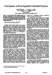
Fig. 1 presents a partial timeline of reconfigurable systems evolution. A previous review on reconfigurable architectures can be found in [7]. The partial and dynamical reconfiguration characteristic is available in a reduced number of reconfigurable devices families. Only Atmel and all Xilinx Virtex [8] families are currently commercialized. Just a few reconfigurable systems really use partial and dynamical reconfiguration features, due to design complexity, the scarceness of tools and documentation targeted to DRS. Some examples of DRSs are presented in Fig. 1. These may load hard IPs at run time, adding flexibility to the system. These systems share three features: (i) complete DRS in a single device with reduced internal communication latency; (ii) coarse grain reconfigurable modules built over fine grain FPGAs; (iii) communication system based on either busses or NoCs. Reconfigurable systems employing busses [2][3][4] were built using different partial and dynamic reconfiguration flows, and have at least two reconfigurable regions connected to the bus. They fulfill almost all required features for a DRS, except for scalability. The Gecko platform [5] is an example of a DRS employing NoC communication. The work presented here has in common with Gecko the use of reconfigurable hard IP cores connected to a NoC. At the architectural level, the contributions of this work are: (i) smaller design complexity than Gecko, since
with one fixed IP, two reconfigurable IPs and macros defining the interface pins. Macros are inserted in the DRS description (e.g. VHDL) and are built using Xilinx FPGA Editor tool or XDL (Xilinx Design Language).
the same network is used for control and data; (ii) low area overhead NoC with explicit support for reconfiguration; (iii) routing interface components specifically designed to support partial reconfiguration. 3.
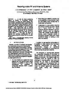
Placement constraints. The second step is to constrain the placement of IP cores and macros, as presented in Fig. 2(B). A floorplanner tool may constrain the placement and shape of the system modules, as well as the placement of macros. Place and route follows the constraints insertion.
DRS FLOW
DRSs reserve one or more regions for runtime reconfiguration. Reconfigurable IP cores that can be loaded in a given reconfigurable region must share some properties: (i) logic of a reconfigurable region must lie inside it; (ii) wires of a reconfigurable region must lie inside it; (iii) fixed communication interface with the rest of the DRS. A flow considering such properties is required. Works [2] and [6] present DRS design flows. The first is specific for Virtex-I family devices, use tristate buffers to communicate a reconfigurable core with the rest of the system and a homemade tool to generate partial bitstreams. The second is the Xilinx Modular Design flow [6], compatible with all Virtex and Spartan-II families. Modular Design uses bus macros (tristate based component) to communicate a reconfigurable core with the rest of the system and BitGen tool to generate partial bitstreams. Flows presented in [2] and [6] have three main drawbacks to connect new cores to the system: (i) busses are limited as communication medium; (ii) tristate buffers in Xilinx FPGAs, used to connect reconfigurable cores, are scarce; (iii) the design flows were not deemed for DRSs.
Routing verification / modification. In the current generation
of Xilinx physical synthesis tools, floorplanning restrictions do not have influence on the routing tool. As illustrated in Fig. 2(B), some wires can still cross reconfigurable region boundaries. If this situation occurs, the associated signal can be disconnected after a reconfiguration step, possibly causing a system malfunction. This situation pervades all reconfigurable design flows, including Xilinx Modular Design. In this case, the designer must either reroute the wire(s) crossing the interfaces or go back to the previous step, to try different placement constraints. The final routing must be similar to the one presented in Fig. 2(C), where no wire crosses a reconfigurable interface. One exception to this rule is the global clock signals, which can safely cross the whole chip. Bitstream generation. A total bitstream is the result of an
ordinary FPGA physical synthesis step. Partial bitstream generation is done by extracting a section of a total bitstream, corresponding to a reconfigurable region. This is illustrated in Fig. 2(D). It is important to include part of the macro component in partial bitstreams to connect the reconfigurable core to the fixed part of the DRS. The method used here to generate partial bitstreams is straightforward, an one-phase flow. Assignment of another core to the same region requires partially repeating the flow for each core, while keeping the same placement constraints.
Reconfigurable interfaces. A reconfigurable interface is an interface between a fixed and a reconfigurable region or between two reconfigurable regions. To enable the use of reconfigurable IP cores, it is necessary to impose two restrictions in reconfigurable interfaces: reconfigurable IP cores sharing the same region must present identical interfaces (in terms of number and type of signals) and identical placement of interface pins. One way to define reconfigurable interface pins is to insert pre-defined feedthrough components, named macros. Fig. 2(A) illustrates a system
‘A
85
87
CAL1024 XC3000
91
95
93
XC4000
University Industry
KressArray Matrix
03
01
Virtex-2 Virtex-2 Pro
AT40k DReAM Stratix Spartan Spartan 2
RAW
05
CHESS
Communication medium based on busses Communication based on a NoC
Virtex 4
Spartan 3
Systolic Ring Dyer
Walder
Palma
R8NR Huebner
Gecko
Reconfigurable System
Source of the work:
99
AT6000 XC6200 Virtex
CLi6000 CLAy
Legend:
97
Reconf 2
Reconfigurable Device
XC2064
89
B routing problem
Fixed Fixed
Reconf 1
Reconf Reconf 1 2
Macro component
C
D
Fixed
Reconf Reconf 1 2
Reconf 1
Reconf 2
Fig. 1. Reconfigurable systems and devices evolution. Fig. 2. Proposed DRS flow.
NOC WITH RECONFIGURATION SUPPORT
As mentioned before, macros are inserted between the reconfigurable core and the router. It is possible to block signals during reconfiguration using an R2F macro, designed with FPGA slices. Fig. 3 presents the atomic structure of this macro. The slice at the right side is configured as a feedthrough, while the slice at the left side implements two AND gates. The width of the whole macro is 8 bits, since a Virtex-II (Pro) CLB contains 4 slices. If the control signal is asserted, transitions at the reconfigurable side of the system are not propagated to the router. The use of slices instead tristate buffers results in smaller number of routing problems [3] and wider interfaces between regions. Fixed Region
Slice R
Control packets: structure and function. Sideband signals
Artemis router to router interface signals. The addition of
two sideband signals per port in the original Hermes router
Fig. 3. R2F macro atomic structure. The F2R macro, used to send data from router to the reconfigurable core is simpler, changing the AND gates by another feedthrough. This simplification is possible because data is not transmitted during reconfiguration to the reconfigurable core, since data packets are discarded by the router. The complete interface between the Artemis router and a reconfigurable core is presented in Fig. 4. reset reconf_n
8 N 8 W
identify control packets transmitted between routers. Control packets have two flits. The first is the XY target address and the second is the operation code to be executed by the router (01 to disable communication and 00 to reestablish communication). The first control packet disables communication between the router and the reconfigurable core, isolating it. This action allows discarding packets and avoiding spurious data to enter into the network. When communication is disabled, the router discards eventual data packets sent to the core under reconfiguration, since those packets would block network paths and were not supposed to be sent while the reconfiguration is occurring. Isolation also protects the network, since during reconfiguration transients can occur in the reconfigurable interface. The second control packet reconnects the reconfigurable core to the network. This control packet is sent once reconfiguration finishes, enabling router normal operation.
Reconfigurable Region
Reconfigurable Core
This work proposes to use a NoC to transfer data among cores (data packets) and reconfiguration control services (control packets). A NoC supporting reconfiguration is build on top of the Hermes NoC [9], named Artemis. The original Hermes NoC does not have any support to partially and/or dynamically reconfigure a given core. The first action before reconfiguring a core is to isolate it from the rest of the system, enabling its substitution without causing interference in other NoC communications. Accomplishing core isolation requires three additions in Hermes: (1) definition of control packets; (2) insertion of sideband signals in router interfaces to mark control packets; (3) transmission of control packets.
4.1 Reconfigurable core to router interface
Control
4.
Control packets transmission. The reception and forwarding of control and data packets are similar. The major change in the router is the addition of one bit at each position of the input buffer. This is required to propagate the value of the ctrl_out signal until the reconfigurable core router. When the control packet arrives at its destination router, it is decoded and the corresponding operation is executed.
Router
reset tx ack_tx data_out rx ack_rx data_in
Macros R2F F2R R2F F2R
E
ing the DRS flow. The first one arrives with the assignment of different cores to the same reconfigurable region. The second one arrives with the assignment of the same core to different reconfigurable regions. It is possible to avoid the second situation if the same bitstream can be loaded at different regions. This procedure is named core relocation. A core originally synthesized for one reconfigurable region can be moved to another one, without resynthesis. Relocation can be useful in at least four different situations: (i) when several reconfigurable regions exist where a core can be loaded; (ii) when it is difficult to constrain the core to a specific region; (iii) when the core has timing constraints difficult to be reached by the synthesis tools; (iv) when two cores that communicate frequently are placed far from the other. Core relocation also reduces the memory requirements to store partial bitstreams, diminishing system cost.
serves to differentiate control packets from data packets. These signals are ctrl_in and ctrl_out.
NoC Router
Core relocation. Two situations require to partially repeat-
reconf
reset tx ack_tx data_out rx 8 ack_rx data_in 8
reset rx ack_rx data_in tx ack_tx data_out
Reconfigurable Core
S
Fig. 4. Router to reconfigurable core interface.
The interface between the router and the reconfigurable core does not contain the ctrl_in and ctrl_out signals because reconfigurable cores neither send nor receive control packets. The reset is a global signal used to initialize the entire system. The router asserts the reconf_n signal to initialize the reconfigurable core connected to the local port. The reconf signal in Fig. 4 connects to the control signal in Fig. 3, controlling the connection from the reconfigurable core to the router. 5.
PROOF OF CONCEPT CASE STUDY
11
Fixed
Reconf.
6.
Core
LUTs
FFs
BRAMs
CLB Cols
R8 RS-232 NoC Mult Div Sqrt
794 411 1678 162 245 220
313 261 864 257 259 269
2 -
5 5 5
CONCLUSIONS AND FUTURE WORK
The present work contributes to lessen the limitations of DRSs in the communication and design flow aspects. Artemis adds reconfiguration control capability to the wellknown advantages of using NoCs for efficient SoC communication. All this is obtained using a single, low-area overhead infrastructure. The second contribution is a design flow specifically built for DRSs. The main advantage of this flow is a reduced number of steps compared to other flows. The flow also employs new macros that guarantee correct operation of the rest of the system during reconfiguration, while sparing components scarcely available in Virtex FPGAs like tristate buffers. Future works include: (i) validate IP relocation; (ii) use Virtex-II ICAP interface to allow faster and internal selfreconfigurable systems; (iii) enable the use of a bidimensional reconfiguration model, allowing the use of more than one reconfigurable IP in the same column.
This research was supported partially by CNPq (Brazilian Research Agency), project 307655/2003-2.
Macros
10
Region
ACKNOWLEDGEMENTS
Core 2
00
Core 1
01
Artemis NoC
Processor
Serial
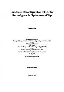
In order to validate the Artemis NoC connected to reconfigurable cores, the system presented in Fig. 5 was prototyped in a Memec Insight MB1000 platform with a VirtexII XC2V1000 device. The system has a 2x2 NoC with a simple 16-bit processor, an RS-232 serial interface core and 2 reconfigurable cores connected to it. The RS-232 serial interface is responsible to send and receive packets to and from the network, providing an interface with a host computer, acting as a configuration controller. The processor is a 40-instruction, load store architecture, with 16x16 register file, non-pipelined. The processor uses two internal 18 Kbits RAM blocks as a unified instruction and data cache, providing 2K addressable words. Until now, three reconfigurable cores were wrapped to be connected to the Artemis NoC: “mult”, “div” and “sqrt”.
Table 1. Case study area report.
Fig. 5. Case study floorplanning. In this case study, the host computer serves as a Configuration Controller (CC), being responsible to: (i) receive reconfigurable core access requests; (ii) configure a core in a reconfigurable region chosen by the CC; (iii) receive acknowledgments of reconfigurable cores that are no longer used. Table 1 presents the area report for each core of the system. It is assigned five CLB columns to each reconfigurable IP core. The partial bitstream of the reconfigurable area corresponds to 9.17% of the total bitstream.
REFERENCES [1] Dyer, M.; et al. “Partially Reconfigurable Cores for Xilinx Virtex”. In FPL’02, pp. 292-301. [2] Palma, J.; et al. “Core Communication Interface for FPGAs”. In SBCCI’02, pp. 183-188. [3] Huebner, M.; et al. “Real-Time LUT-Based Network Topologies for Dynamic and Partial FPGA SelfReconfiguration”. In SBCCI’04, pp. 28-32. [4] Walder, H.; Platzner, M. “A Runtime Environment for Reconfigurable Hardware Operating Systems”. In FPL’04, pp. 831-835. [5] Marescaux, T.; et al. “Run-Time Support for Heterogenous Multitasking on Reconfigurable SoCs”, Integration, the VLSI Journal, v. 38(1), Oct. 2004, pp. 107-130. [6] Lim, D.; Peattie, M. “Two Flows for Partial Reconfiguration: Module Based or Small Bit Manipulations”, Xilinx Application Note 290 (XAPP290 v1.2), Sep. 2004, 28 p.. [7] Hartenstein, R. “A Decade of Reconfigurable Computing: a Visionary Retrospective”, in DATE’01, pp. 642-649. [8] Xilinx, Inc. www.xilinx.com. [9] Moraes, F.; et al. “HERMES: an Infrastructure for Low Area Overhead Packet-Switching Networks on Chip”, Integration, the VLSI Journal, v. 38(1), Oct. 2004, pp. 69-93.