fabricators, and not merely be a âdesign specificationâ that designers send .... going to be manufactured), layer generation (slicing of the CAD model to generate ...
IFIP WG5.2 Geometric Modelling Workshop, Dec.7-9, 1998, Tokyo
Representation and Processing of Heterogeneous Objects for Solid Freeform Fabrication Vinod Kumar†, Sanjay Rajagopalan‡, Mark Cutkosky‡ and Debasish Dutta†
1.0 Introduction Solid Freeform Fabrication (SFF), also referred to as Layered manufacturing (LM), is a new method of fabrication. Unlike conventional manufacturing (e.g., CNC machining), where a part is fabricated by selectively removing material from a workpiece, in SFF, a part is built by depositing material, layer-by-layer, under computer control. Solid Freeform Fabrication is in principle a 2.5D process - stacking up layers - with the advantage that the part’s geometric complexity has little impact on the fabrication process. An attractive and powerful feature of SFF, yet to be fully exploited, is the ability to deposit several materials in varying composition within a layer and also vary materials between layers. Also, by depositing different materials, in varying proportions, the part can be endowed with varying microstructure. Advances in mechanical and structural design have led to the development of mathematical techniques for the design of topology and material microstructure of such “heterogeneous” objects. For example, the homogenization design method (HDM) can be used to derive material microstructure and density distribution for a part corresponding to designer-prescribed properties; e.g., parts with negative Poisson’s ratio can be designed [4]. Conventional manufacturing techniques cannot realize such novel and efficient designs. The fabrication of functional parts is becoming technologically viable [7]. However, functional parts with designer specified tolerances and surface finish are likely to require accurate material addition and removal processes. Therefore, we consider a manufacturing paradigm predicated upon the synthesis of material addition (deposition, lamination, embedding etc.) and material removal (milling, EDM, etc.). In this paper, our use of the term “solid freeform fabrication” and “layered manufacturing” includes both purely additive processes such as Selective Laser Sintering (SLS) [9], Direct Metal Deposition (DMD) [16][17], etc. and hybrid methods like Shape Deposition Manufacturing (SDM) [18] which involves material deposition and removal operations. In such manufacturing environments, more sophisticated information regarding the part to be fabricated needs to be exchanged between designers and manufacturers. Researchers, industry experts and standards organizations are grappling with the issue of defining an
† Department of Mechanical Engineering, University of Michigan, Ann Arbor, MI 48109, USA ‡ Department of Mechanical Engineering, Stanford University, Stanford, CA 94305, USA 1
adequate interface and information exchange “language” between designers and SFF service providers [23]. We believe that the ability to specify heterogeneous objects, along with other engineering data will be essential for any future interchange format [6]. Additionally, the format will need to accommodate a two way dialogue between designers and fabricators, and not merely be a “design specification” that designers send downstream. In this paper, we shall describe our ongoing work that deals with development of techniques for modeling and representation of heterogeneous objects and the process planning for their layered manufacturing. We also demonstrate how the basic entities for modeling heterogeneous objects can be extended and used as building blocks to create an interface format for meaningful information exchange between design and fabrication.
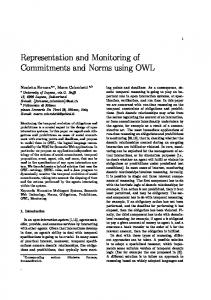
2.0 Heterogeneous Objects Heterogeneous objects are composed of different constituent materials with possibly varying composition and/or microstructure. In other words, they are composite materials having non-homogeneous character at a microscopic scale. We consider a heterogeneous object to made of a finite number of material domains. Each material domain could be: • Homogeneous: This implies that the material is uniform throughout the region. The material for each domain could be a metal, ceramic, alloy or an embedded component. If composed of alloys, the material domain is assumed to have no variation in composition of the alloy. Heterogeneous objects made of only these domains are also referred to as multi-material objects. The separate homogeneous regions provide definable internal material boundaries inside the object. Figure 1(a) shows a multi-material object with two material domains - an epoxy rotor and polyurethane shaft. • Graded: The region is composed of several materials with varying composition. One of the material could be void (to describe porous regions). For graded domains, there is no homogeneity and, the heterogeneous object does not possess any definable material boundaries due to these domains. Figure 1(b) shows a sample part made of stainless steel and invar with a graded zone. The greyscale variation is due to the differential oxidation of invar and stainless steel. Figure 1(c) shows the diagram of an injection molding tool fabricated by SDM. It consists of an invar core (low coefficient of thermal expansion), embedded copper deposits and conformal cooling channels (for quicker heat dissipation), and a stainless-steel shell (for corrosion resistance). The stainless-invar boundary is gradually graded to reduce thermal stresses at the interface.
2
(a)
Polyurethane shafts and epoxy rotors
(b)
(c)
Stainless steel Invar
Graded
Copper
FIGURE 1. Parts fabricated by SDM process (a) Multi-material part (b) Graded material part (c) ALCOA Injection molding tool (Source: Rapid Prototyping Laboratory, Stanford University)
2.1 Issues in the Fabrication of Heterogeneous Objects As mentioned, the deposition of material in SFF processes can be explicitly controlled thereby providing unique opportunities to selectively deposit material. The material deposited can be varied from to region to region to create a multi-material object or, varied continuously to yield a heterogeneous object. Figure 2 shows a schematic of various stages involved in the design and manufacture of heterogeneous objects. The CAD model and process planning plays an important role in the automated fabrication of heterogeneous objects.
3
Our focus in this paper is on modeling heterogeneous objects and process planning of these models for SFF. The CAD model of the object will possess not only the geometry information but also the material data at each point within the object. We refer to such a CAD model as Heterogeneous Solid Model (HSM). This HSM can then be processed to generate manufacturing data for any SFF process. Next, we briefly discuss issues related to the modeling and process planning of heterogeneous objects.
M E T H O D S
DESIGN
CAD MODEL
PROCESS PLANNING
FABRICATION
Optimal Design Compositional Design (Pre-processed Library Components)
Heterogeneous Solid Model
Orientation Support Creation Compact Generation Slicing Path Generation
SDM, DMD etc.
FIGURE 2. Stages in the design-manufacture of heterogeneous objects
2.1.1 Modeling Issues Presently, all commercial SFF processes require that the CAD model of the part to be manufactured be converted to the STL format prior to fabrication. Roughly speaking, the STL representation is a faceted surface description of the solid part with an orientation for each facet (a triangle), but without any adjacency information. Although simple and universally accepted, there is a growing dissatisfaction with the STL format among SFF users [11]. Other popular representation schemes, e.g., B-rep and CSG, also represent the boundary and assume a homogeneous interior. What is necessary now is the inclusion of material (solid interior) information such that the models can be efficiently manipulated and processed for SFF. The designs generated by the optimization techniques such as HDM possess spatial material variation along with the geometry information. New solid modeling schemes (hetero4
geneous solid models) have to be developed to mathematically capture both the geometry and the material information generated by these designs. The HSMs would provide the missing link, enabling the fabrication of such heterogeneous designs by SFF processes. The need for HSM was identified in [11]. In the future, analysis and design synthesis tools can be developed which can aid in creating heterogeneous objects from methods other than optimal design (such as HDM). 2.1.2 Process Planning Issues Since layered manufacturing involves building the object by stacking up layers, “design decomposition” is a natural framework for process planning. Reversing information flow, a designer could also work with pre-process planned elements to create the object. We refer to this as “compositional design”. We remark on each further. Design Decomposition: Typically, the input to the SFF fabrication system is a geometric model of the finished design. The CAD model of the object is processed to generate the information required to drive the SFF machine. The sequence of steps that lead to the fabrication of objects in SFF from the CAD model are termed as process planning tasks [15]. These tasks include selection of the growth direction (the orientation in which the object is going to be manufactured), layer generation (slicing of the CAD model to generate planar contour data which is needed to deposit material in a layer) and path planning/generation (the trajectory to fill in the material inside the contour and subsequently shape it if needed). New methods for process planning have to be developed to operate on HSMs and generate the required information for the SFF machine. Compositional Design: Clearly, the decomposition approach outlined above gives the designer a lot of flexibility, but could lead to several design-manufacturing cycles due to manufacturability problems (e.g., minimum allowable feature size, material compatibility issues, etc.) in the submitted design. An alternative approach is to supply designers with pre-processed library components which they can transform (according to some prescribed rules) and use to construct their design. These components could be generic shapes (cylinders, cuboids etc.) or functional entities (shafts, bearings, gears etc.). The CAD system can be augmented to automatically carry out many of the process planning tasks as the design is being generated [5], and offer early manufacturability analysis to the designer. The use of such pre-processed components limits the designer's flexibility, but carries with it a “guarantee” of manufacturability if used properly. In the next two sections, we present our ongoing work related to the issues mentioned above. In Section 3.0, we describe a heterogeneous modeling scheme to represent both the geometry and material information of heterogeneous objects. These models are then post processed for fabrication by SFF processes as discussed in Section 4.0.
3.0 Heterogeneous Solid Modeling Heterogeneous solid modeling aims to incorporate material information along with the geometry. Our work in this regard is described in detail in [12][13]. In this section, we summarize the results. 5
3.1 Model for geometry Current solid modeling methods model objects by capturing its geometrical information. The mathematical space chosen for modeling the geometry is the Euclidean space E3, referred to as geometry space. Each point p in the object S is represented as a geometric point x in E3. Thus, subsets of E3, called r-sets, are chosen to characterize the geometry of the object S. An r-set is defined as a compact, regular, semi-analytic subset of E3. An r-set can be disconnected. Therefore, an object consisting of several disconnected components can also be modeled with a single r-set. Geometric transformations can be applied to r-sets to transform them in E3. Any two r-sets can be combined using a set of modeling operations called regularized operations (regunion ∪*, reg-intersect ∩* and reg-difference /*). Regularization implies closure of the interior of the pointset. These regularized operations are algebraically closed in the class of r-set. Refer [8][22] for more details.
3.2 Model for heterogeneous material Heterogeneous objects are composed of different constituent materials (also referred to as primary materials) which are present in varying proportions. It is assumed that the number of primary materials (n) is finite. The material at each point p in the object S is a combination (mixture) of the ‘n’ primary materials and is specified by the volume fractions of these primary materials. The material composition of any point p is represented as a material point v in Rn, with each dimension representing one primary material. Noting that these volume fractions must sum to unity, we can precisely define the space of material points V (material space) as:
n V = v ∈ R
v 1≡ v i = 1 and v i ≥ 0 i=1 n
∑
(EQ 1)
where || . ||1 denotes the L1-norm and, vi (i-th component of v) represents the volume fraction of i-th primary material. Thus, any point v ∈ Rn can represent a material composition only if v ∈ V ⊂ Rn. Note that porosity of a local region can also be modeled by including void as one of the primary materials. A set of n points (m1, m2,..., mn) called the primary material points can be defined in V to represent the ‘n’ primary materials. The coordinates of these primary material points in V are defined as: j
v i ( m ) = δ ij
(EQ 2)
Note that this framework can be used to represent objects made of distinct material domains. In such a case, only the primary material points needs to be used. A simpler model for such objects is to use a finite subset of integers K ⊂ Z+ to form the material space with each point a ∈ K representing a unique material. However, the model presented above can represent material variation and is adopted as a generic framework. 6
For each point p in S, the geometrical point x is associated with its corresponding material point v as a mapping from E3 to Rn: 3
F: E → V
3
F(x ∈ E ) 1 = 1 F ( x ) ≡ v ( x ) = { vi ( x ) }
(EQ 3)
We term F as the material function. Additional constraints can be placed on this material function F when defining an appropriate model for S.
3.3 Heterogeneous Solid Model An appropriate mathematical space to model heterogeneous objects is the product space T = E3 × Rn. Specifically, the material points are restricted to lie in the material space V ⊂ Rn. Each point p ∈ S can be modeled as a point (x ∈ E3, v ∈ V) in T, where x and v (or equivalently, F(x)) are the geometrical and material points respectively. Material r-set (rm-set): An rm-set is defined as a subset D = (P, B) of T where P ⊂ E3 is an r-set and B ⊆ V assigns material to P. The set B is specified by material function F which is required to be C∞. Thus, an equivalent definition of rm-set is the pair (P, F) where the subset B is defined implicitly through its the material function as F(P). Material Object (rm-object): An rm-object S is defined as a finite collection of rm-sets {Dj} = {(Pj, Bj)} such that the conditions C1 and C2 hold: • •
C1: The rm-sets are geometrically interior-disjoint (i.e., the r-sets are interior-disjoint). C2: The rm-sets are minimal i.e., there does not exist two rm-sets which can be combined into a single rm-set. In other words, if there exist two rm-sets whose material functions (which are C∞ functions) can be combined into a single C∞ function, then their geometry is combined into an r-set with one C∞ material function attached.
S = { D j } = { ( P j, B j ) }, j ∈ J (finite) P i ∩ * Pk = φ, i ≠ k, ∀i, k ∈ J
(EQ 4)
B j = F j(P j) The rm-object is defined as the mathematical model for representing heterogeneous objects, also called the heterogeneous solid model (HSM). The geometry is captured by rsets and the material variation is specified in each r-set by material functions. Modeling operation enhancements are defined to create and manipulate rm-objects as a combination of the regularized boolean operations on r-sets and the combine operation on the material points. Refer [13] for more details. 7
Our initial computer implementation of HSM (rm-objects) utilizes the ACIS B-Rep kernel [1]. The data structure is appropriately modified to accommodate the material dimension. Each object is modeled as an rm-object and the geometry is defined through a set of r-sets, instead of a single r-set. The material distribution is represented as an additional module in the B-Rep scheme. Also, links to the material module is established at all levels of the data structure to enable model interrogation and manipulation.
3.4 Example An object similar to the one shown in Figure 1(a) is modeled using the heterogeneous solid modeling scheme described above. The object is modeled as an rm-object (HSM) with two rm-sets. The wheel is modeled as an rm-set, the material being epoxy. The second rm-set models the shaft made of polyurethane.
RM-OBJECT
RM-SET 1
{Wheel geometry, Epoxy}
RM-SET 2
{Shaft geometry, Polyurethane}
FIGURE 3. Heterogeneous Solid Model of a Multi-Material Part 8
4.0 Processing of Heterogeneous Solid Modeling for SFF The use of heterogeneous solid models, such as described above, in the process planning enables the automatic generation of valid and useful SFF manufacturing data. There are three tasks that typically need to be performed before a design can be process-planned and fabricated. These are: i. Selection of a growth direction (or part orientation during fabrication). ii. Construction of a support structure that enables overhang features in the design [2]. iii. Decomposition of the supported model into simple features suitable for automatic tool-path (or deposition-path) generation. We discuss two modes by which this information can be encoded into heterogeneous models - design decomposition and compositional design. The focus is towards creating a clean and unambiguous interface between (heterogeneous object) design and SFF. A key component is an intermediate “decomposed” representation of the design - one in which the growth direction has been determined, the support structure added, and the supported design decomposed into simple entities (called “compacts”) that make only a minimal set of assumptions about the actual fabrication process used to make the artifact.
4.1 Extension of Modeling Entities In this section, we present the entities that are used to describe a decomposed design. These entities (called SFF-Compacts and SFF-Objects) can be thought of as extensions or “derived classes” of the heterogeneous modeling entities described earlier. First we explain the concept of a compact. A compact has been defined [5][18][21] as the maximum 3D increment of geometry that can be fabricated within a single cycle of material addition and (optional) material removal. A compact can be considered a “logical” decomposition, as it is based on geometric and material constraints that are fundamental to the process (i.e. tool access, support of overhangs etc.), and not constraints that could change as the process evolves. Downstream processes may choose to further decompose compacts into simpler entities (e.g. 2.5D layers) depending upon their specific manufacturing constraints. The only geometric requirement that compacts satisfy is that they are convex monotones in the direction perpendicular to a prescribed growth axis (A simple solid is a convex monotone with respect to a line l if, for every line lp orthogonal to l, the intersection of the solid with lp is connected). Figure 4 illustrates this concept.
9
FIGURE 4. Shape Decomposition of a multi-material solid
SFF-Compacts: SFF-Compacts are extended rm-sets that implement the above concept. In addition to geometry and material information which is inherited from the rm-sets, compacts also have a unique growth direction, a build order field (which is used to assemble SFF-Compacts into SFF-Objects), and a material precedence field (which is used to implement merging and splitting algorithms that operate on SFF-Objects). In some cases, the material boundaries between rm-sets might not be critical and would not need intermediate shaping operations. Then, it is possible to combine several adjacent SFF-Compacts into a single SFF-Compact with multiple materials and adopt a single deposition strategy (assuming the desired properties are achievable by deposition alone). If these multi-material SFF-Compacts are to be used, they have to be derived from an rmobject and not an rm-set. Such possibilities can be explored to incorporate global optimum deposition strategies for a particular SFF process. However, in the interest of wide applicability and process independence, we assume that a SFF-Compact is derived from an rmset. In any case, the part-support boundary is always assumed to have accurate definition, and compacts are always split at the part-support boundary (since support structures are extraneous to the design). SFF-Objects: SFF-Compacts do not have much significance in and of themselves, and are partial object prescriptions. In order to represent a real object, they need to be assembled into a collection called an SFF-Object. An SFF-Object can also be thought of as an extended rm-object, where each member is an SFF-Compact, and whose minimality condition (C2) has been dropped. Also, some constraints and dependencies are enforced between the geometry, material, growth axis, build-order and precedence fields of all SFF10
Compacts within a single SFF-Object. Some of the important constraints (a few of which are inherited from the rm-object definition) are: i. The SFF-Compacts that constitute an SFF-Object partition the SFF-Object into a finite number of pair-wise disjoint regions. ii. The closure of the interior of all the SFF-Compacts in an SFF-Objects is exactly equivalent to the union of all the compacts (i.e., there are no extraneous “voids” within an object - internal cavities are explicitly modeled with material type set to “air”, for example). iii.All SFF-Compacts within an SFF-Object are similarly oriented (i.e. share a common growth axis direction). iv. An SFF-Object is fully supported (or encapsulated in support structure) and no two SFF-Compacts with consecutive positions in the build order have the same material type (i.e. the compacts are minimal as long as geometric and material restrictions on a solid are not violated). v. The build order of SFF-Compacts in an SFF-Object is sequential, and decompositions that enforce cyclic ordering are invalid (i.e. they need to be further decomposed until cyclicity is destroyed). See Figure 5.
FIGURE 5. A decomposition that violates the cyclicity constraint
Adjacent SFF-Compacts in an SFF-Object can be identified by performing non-regularized intersections on pairs of compacts. The closure condition (ii) ensures that all set-operatic intersections result in purely lower-dimensional entities. Any two compacts for which the intersection is not null are deemed as adjacent. Precedence ordering can be inferred from the build order field. Compact Adjacency and Precedence Graphs [19] that can be used to make process planning and scheduling decisions by implementing graph traversal algorithms can thus be easily derived as needed from these SFF-Objects.
4.2 Processing of Completed Designs (Design Decomposition) Decomposing the CAD model of a design to generate layer information has been the natural method of fabricating parts in SFF. As mentioned earlier, a build direction is selected 11
for the CAD model, and support structures are created for this orientation to support overhang regions. The supported model is then sliced to generate layer information. Finally, the layer information is used to generate the tool paths for deposition. This sequence of steps has been the traditional approach for fabricating parts in SFF [15]. However, this traditional method of process planning cannot be used for hybrid processes like SDM, which include material removal steps. For such processes, the use of compacts becomes necessary [18][19][21]. Also, with heterogeneous objects, traditional methods need to be extended to allow processing of material information. Here, we propose a process planning framework called Design Decomposition, which encompasses the traditional methods, handles hybrid processes like SDM, and also processes heterogeneous designs that are modeled as HSMs (described in Section 3.0). We introduce an intermediate representation (SFF-Object) as an informationally enriched model that can be interchangeably used and allow a variety of SFF processes to fabricate the part. In this method of operation, the HSMs are first decomposed into SFF-Objects, then further process planned and fabricated by a downstream manufacturing process. The advantage of the intermediate representation is that it incorporates some of the “logical” constraints in SFF, without committing to a particular SFF process. In many cases, it is this “logical” decomposition, and not the “physical” decomposition that represents the bulk of the computational complexity. This decomposed representation can conceivably be sent to multiple processes within a broad process class, and still be valid. Simply put, the decomposed model is a method for encoding generic process planning information into the design representation (in addition to geometry and material information). This capability can be exploited to enable designers to address manufacturability concerns early in the design phase. Figure 6 highlights the difference between the traditional process planning in SFF and the proposed approach. Note that the sliced model is only one of the several possible “physical” decompositions that can be derived from the SFF-Object.
12
TRADITIONAL
HETEROGENEOUS SOLID MODEL Orientation Selection
CAD MODEL
Orientation Selection
Flow of Manufacturing information to design
ORIENTED MODEL Support Creation
ORIENTED MODEL Support Creation
SUPPORTED MODEL
Process Dependent Operations
SUPPORTED MODEL Logical Decomposition
DECOMPOSED MODEL
Slicing
SLICED MODEL Toolpath Generation
Fabrication by an SFF process Additive SFF processes
Process Dependent Operations
Physical Decomposition
PROCESSED MODEL Toolpath Generation
Fabrication by an SFF process Hybrid SFF processes
FIGURE 6. Process planning by Design Decomposition
Selection of an optimal growth direction (which needs to happen before the decomposition of the design into an SFF-Object) is a subject of ongoing research [20]. While some of the criteria used (or the weight applied to a particular criterion used) are process dependent, some other criteria (like minimizing the number of compacts or preserving the geometry of some functional features) could apply equally to a broad class of processes. Thus, the design decomposition will have to be re-generated for any process where the space of feasible orientations differs substantially from those of a broad class of representative processes. 13
Once the orientation is fixed, the support structure can be generated by Boolean operations with the bounding box composed of support stock. Algorithms for the decomposition of oriented and supported solids are described in [21]. A decomposed object can be used to generate tool and deposition paths [10] for fabrication of the part. Figure 6 schematically shows how a heterogeneous solid model (a schematic of the wheel/ shaft example shown in Figure 3) is oriented, supported, decomposed, planned and fabricated.
FIGURE 7. Process Planning and Fabrication of Completed Designs (a) for hybrid processes (b) for purely additive processes
For hybrid processes, the decomposed object is sent to the tool and deposition path planner. The material is deposited in near-net shape and the tool path are generated to accurately machine the new surface. This cycle is repeated as needed. In Figure 7(a), the surface profile that the milling tool cuts after each material deposition step is illustrated. Though it is not illustrated in Figure 7, even the hybrid process planner may further slice the decomposed object. This can depend, for example, upon the maximum possible deposition thickness for a material, the currently available tool-set, thermal considerations etc. All these parameters can be expected to change as the process evolves. For purely additive processes, the intermediate decomposed representation can be sliced (in the traditional manner) and processed in layers as shown in Figure 7(b).
4.3 Designing with Pre-processed Library Components (Compositional Design) While many of the global feature interactions and manufacturability concerns that complicate traditional manufacturing no longer apply to SFF, a large number remain (e.g. mini14
mum allowable feature size, material compatibility issues, thermal issues) [3]. It is well known in the field of Concurrent Engineering that manufacturability concerns addressed early in the product design phase greatly reduce the life-cycle costs of product development. Similarly, it makes intuitive sense that manufacturability concerns addressed during the prototyping phase of the design will greatly reduce the prototyping cycle-time. In order to achieve this, some mechanism for feeding process-planning expertise back to the designers (without requiring them to be process experts) needs to be devised. Designing with pre-processed components is a first step in this direction. In compositional design, designers are supplied with parametric SFF-Objects, along with rules on allowable transformations that can be performed on the objects. These objects have a prescribed growth direction and are fully supported. Algorithms that operate on them in order to transform them(e.g. scale, rotate) or merge them with each other, are implemented as plug-ins to the CAD environment. As the designer constructs a composite object, the software automatically generates the supported and decomposed model of the new entity. The designer then has access to quick manufacturability assessments right at the CAD station. Another advantage of pre-processed library components, especially for processing graded material objects, is that designers can be made aware of preferred orientations for the fabrication process. As an example, Figure 8 shows with glass beads embedded in a urethane substrate, how grading along the growth direction is much simpler (from an implementation standpoint) than grading perpendicular to the growth axis.
FIGURE 8. A preferred orientation enforced due to processing concerns
The library components provided to designers who wish to do compositional design include some generic shapes (e.g. cylinders, cuboids etc) and some ubiquitous functional elements (e.g. electronic circuit, bearing, joint, shaft etc.) [5]. Using the material precedence field, merging algorithms can be made to treat the functional components in an appropriate manner (e.g. never cut an electronic circuit in two, always build a shaft axially etc.). Figure 9 shows a simple example on how pre-processed library elements can be used
15
to generate a design for a wheel/shaft assembly such as that shown in Figure 3, and subsequently be fabricated with minimal processing.
FIGURE 9. Compositional design of a wheel on a shaft using pre-processed elements
4.4 Example The wheel/shaft example modeled in Section 3.4 is processed further for fabrication. In Figure 10, the support structure is generated, and the model is decomposed into SFF-Compacts that form an SFF-Object. The compacts are ordered according to their build order. This SFF-Object can be further processed by the deposition and tool path planner for fabrication by a hybrid process like SDM.
16
HETEROGENEOUS SOLID MODEL
SUPPORTED MODEL
DECOMPOSED MODEL
Modeled as rm-object with three rm-sets
SFF-Object with 7 SFF-Compacts ( in build order ) FIGURE 10. Process planning for the wheel/shaft example using Design Decomposition
In Figure 11, the decomposed model (SFF-Object) is shown sliced to generate planar layers (traditional slicing) using an adaptive slicing algorithm [14]. The SFF-Object has been decomposed into layers which can be manufactured by any purely additive process (e.g. DMD, SLS). Toolpaths for a sample slice is also shown.
17
FIGURE 11. Sliced model and a sample heterogeneous slice for the wheel shaft example
5.0 Summary In this paper we have presented a new approach to modeling and processing of heterogeneous objects slated for solid freeform fabrication. A fundamental advantage of SFF over conventional manufacturing techniques is the capability to access the entire volume of work-piece at some stage of the process (as opposed to only the external surfaces in conventional manufacturing). In order for designers to fully exploit this capability, the solid modeling system needs to accommodate the specification of geometry and (possibly varying) material properties within the entire volume of the part. We have described a two-tier 18
solid modeling method (using rm-sets and rm-objects) by which this can be achieved for arbitrary design geometries. Process planning of heterogeneous objects requires the determination of a near-optimal orientation for the part, the generation of a support structure and subsequent decomposition of the part into simpler entities that are conducive to automated fabrication. However, this mode of operation does not allow for easy and early communication of process-planning concerns to designers who are not already process experts. One method of early communication is to provide designers with pre-processed library components, and rules for transforming and merging them into designs. We have discussed how the heterogeneous modeling entities can be extended (as SFF-Compacts and SFF-Objects) to form an intermediate decomposed representation of the design. The representation, along with a compositional design library, acts as the “interface” that enables a two way communication between design and manufacture. This interface preserves the flexibility available to designers today, postpones commitment to a particular process, and enables novice designers to quickly compose manufacturable parts. We believe that the techniques described in this paper can form the basis for a expressive and robust information exchange language between designers of mechanical systems and rapid-prototyping service providers.
6.0 Acknowledgements The authors from Stanford would like to thank Prof. Fritz Prinz, Alexander Cooper, John Fessler and Alex Nickel of the Rapid Prototyping Laboratory at Stanford, for use of their parts as examples. We would also like to acknowledge financial support from NSF under MIP-9617994 and MIP-9618050. The authors from University of Michigan gratefully acknowledge the financial support from ONR grant N00014-97-1-0245 and NSF grant MIP-9714951.
7.0 References 1. ACIS Geometric Modeler: Application Guide, Spatial Technology Inc., 1995. 2. S. Allen and D. Dutta, “Determination and Evaluation of Support Structures in Layered Manufacturing”, Journal of Design and Manufacturing, Vol. 5, pp. 153-162, 1995. 3. C. H. Amon, J. L. Beuth, L. E. Weiss, R. Merz, F.B. Prinz, “Shape Deposition Manufacturing with Microcasting: Processing, Thermal and Mechanical Issues” ASME J of Manufacturing Science & Engineering, Vol. 120, pp. 656-665, August 1998. 4. P. M. Bendsoe, and N. Kikuchi, “Generating Optimal Topologies in Structural Design Using a Homogenization Method”, Computer Methods in Applied Mechanics and Engineering, Vol. 71, pp. 197-224, 1988.
19
5. M. Binard and M. Cutkosky, “Building Block Design for Layered Manufacturing”, ASME-DETC, Design for Manufacturing Conference (DFM123), Atlanta, September 1998. 6. D. Dutta, V. Kumar, M. Pratt and R. Sriram, “Towards STEP-based Data Transfer in Layered Manufacturing”, Tenth International IFIP WG5.2/5.3 Conference, (PROLOMAT), Italy, 1998. 7. J.R. Fessler, A.H. Nickel, G. Link, F.B. Prinz and P. Fussell, “Functional gradient metallic prototypes through Shape Deposition Manufacturing”, Proceedings of the Solid Freeform Fabrication Symposium, University of Texas at Austin, August 1997. 8. C. M. Hoffmann, Solid & Geometric Modeling: An Introduction, Morgan Kaufmann Publishers, 1989. 9. L. Jepson, J. Beaman, D. Bourell, “SLS Processing of Functionally Gradient Materials”, Proceedings of Solid Freeform Fabrication Symposium, Austin, pp. 67-80, September 1997. 10. J. Kao, and F. B. Prinz, “Optimal Motion Planning for Deposition in Layered Manufacturing”, ASME Design Engineering Technical Conferences, Atlanta, Georgia, September 1998. 11. V. Kumar and D. Dutta, “An Assessment of Data Formats for Layered Manufacturing”, Advances in Engineering Software, Vol. 28, No. 3, pp. 151-164, April 1997. 12. V. Kumar and D. Dutta, “An Approach to Modeling Multi-Material Objects”, ACM Solid Modeling Conference, pp. 336-345, Atlanta, May 1997. 13. V. Kumar and D. Dutta, “An Approach to Modeling and Representation of Heterogeneous Objects”, Accepted for publication in ASME Journal of Mechanical Design, (December), 1998. 14. V. Kumar, P. Kulkarni and D. Dutta, “Adaptive Slicing of Heterogeneous Solid Models for Layered Manufacturing”, ASME-DETC, Computers in Engineering Conference, Atlanta, September 1998. 15. A. Marsan and D. Dutta, “A Survey of Process Planning Techniques for Layered Manufacturing”, Proc. 1997 ASME Design Automation Conference, Sacremento, September, 1997. 16. J. Mazumder, J. Choi, K. Nagarathnam, J. Koch and D. Hetzner, “Direct Metal Deposition of H13 Tool Steel for 3-D Components”, Journal of Minerals, Vol. 49, No. 5, pp. 55-60, May 1997. 17. J. Mazumder, J. Koch, K. Nagarathnam and J. Choi, “Rapid Manufacturing of Laser Aided Direct Deposition of Metals”, preprint, Department of Mechanical Engineering, University of Michigan, Ann Arbor, 1996. 18. R. Merz, “Shape Deposition Manufacturing”, Ph.D. Dissertation, Technical University of Vienna, Austria, 1994. 19. J. M. Pinilla, J. Kao, and F. B. Prinz, “Process Planning and Automation for AdditiveSubtractive Solid Freeform Fabrication”, Proceedings of the Solid Freeform Fabrication Symposium, University of Texas at Austin, August 1998. 20
20. S. Rajagopalan and J. M. Pinilla, P. Losleben, Q. Tian and S. K. Gupta, “Integrated Design and Rapid Manufacturing over the Internet”, ASME-DETC, Computers in Engineering Conference, Atlanta, 1998. 21. K. Ramaswami, Y. Yamaguchi and F. Prinz, “Spatial Partitioning of Solids for Solid Freeform Fabrication”, Proceedings of 4th ACM Solid Modeling Symposium, May, Atlanta, pp. 346 - 353, 1997. 22. A. Requicha, “Representations for Rigid Solids: Theory, Methods and Systems”, Computing Surveys, Vol 12, No. 4, 1980. 23. Workshop on New Paradigms for Manufacturing, A. Mukherjee and J. Hilibrand, Editors, The National Science Foundation, Computer and Information Science and Engineering Directorate, Microelectronics Information Processing Systems Division, May 2-4, 1994.
21