Hindawi Publishing Corporation International Journal of Distributed Sensor Networks Volume 2014, Article ID 750601, 15 pages http://dx.doi.org/10.1155/2014/750601
Research Article Design Approach Based on EtherCAT Protocol for a Networked Motion Control System Lei Wang,1,2 Muguo Li,2 Junyan Qi,1 and Qun Zhang2 1 2
School of Computer Science and Technology, Henan Polytechnic University, Jiaozuo 454000, China State Key Laboratory of Coastal and Offshore Engineering, Dalian University of Technology, Dalian 116024, China
Correspondence should be addressed to Lei Wang; wang
[email protected] Received 28 September 2013; Revised 5 December 2013; Accepted 17 December 2013; Published 13 February 2014 Academic Editor: Gelan Yang Copyright © 2014 Lei Wang et al. This is an open access article distributed under the Creative Commons Attribution License, which permits unrestricted use, distribution, and reproduction in any medium, provided the original work is properly cited. This paper presents a new design approach based on EtherCAT protocol aiming at a special networked motion control system. To evaluate this system, the testing platform of the networked motion control system for ocean wave maker is designed. The paper gives the detailed design for the testing platform including software and hardware. With message access delay and jitter, a set of experiments are done to evaluate the crucial performance for the implemented networked motion control system. By analyzing the experimental results, the systemic performance is verified. And the design approach can be widely extended to other automation application scenarios.
1. Introduction Motion control, as a subfield of automation, has been finding applications in a broad range of areas such as packaging, printing, textile, semiconductor production, and assembly industries. As the number of the devices of motion control system increases, distributed networked motion control systems are desired in various manufacturing fields. This kind of system must be able to access a mass of device information from any locations in factory floor. In order to solve this problem, various serial communication networks have been designed and implemented to provide reliable and efficient communication paths for data exchange among the system components [1]. In the last two decades, hundreds of proprietary digital network communication protocols named fieldbus have been developed. The construction of networked motion control systems by fieldbus has become a hot topic. In particular, the fieldbuses have been widely used in a great deal of motion control applications for robotics, passenger cars, and aircrafts [1–3]. Nonetheless, because of the relatively low bit rates and (sometimes) changing cycle times, the fieldbuses are difficult to cope with the existing systemic needs for the transmission of a higher quantity of information with the tight timing constraints. Moreover, the software
and hardware of multivendor products are incompatible [4]. It is quite difficult to connect the equipment of different manufacturers. Due to ubiquity, high speed, simplicity, and low cost, Ethernet seems to be the most promising candidate for “the one” network technology to replace fieldbus [5]. Whereas Ethernet is not originally designed for real-time control, the most significant problem is that it is nondeterministic due to its bus arbitration scheme [6]. There are mainly three methods to modify standard Ethernet, including adding an industrial-automation specific application layer on top of TCP/IP, using the priority scheme at the Ethernet MAC layer, and intervening into the scheduling procedure of the MAC layer [7, 8]. The modified Ethernet protocols are called Industry Ethernet protocols which integrated the advantages of both the real-time capability and the merits of Ethernet. So many industrial companies and institutes have shown interests in developing Industry Ethernet protocols. And Industry Ethernet has become the de facto standard for industrial automation networks and widely used in automation and process control domain. In recent years, various Industry Ethernet protocols, such as SERCOS, POWERLINK, ProfiNet/ProfiNet IRT, and EtherCAT, have been proposed to develop networked control systems which have
2 the control loop closed through a communication network [9–11]. Several researchers also applied the Industry Ethernet technology in motion control [12–14]. Also some analysis and evaluation on the performance of Industry Ethernet protocols have been done [7, 15–18]. At the same time, a considerable number of Industry Ethernet protocols have been introduced into motion control systems to implement networked motion control [19]. However, few researchers investigate the hybrid networked motion control systems with multiaxes servo motors and a great deal of sensors [20]. In view of the special application requirement for high real-time performance and the large amounts of information transmission, we design ocean wave maker networked motion control systems. The system should accurately simulate ocean waves in the experimental basin and quickly get the experimental data to provide reliable basis for engineering design and scientific research from field sensors. Therefore, the system is constructed with a large number of distributed data acquisition modules and multiservo motors in the field of ocean engineering application. This system should be provided with the capability for transmitting motion control commands and feedback information with lower delay and jitter. Meanwhile, it can help acquire the high efficiency and high real-time large-capacity data more effectively. As a very popular Industry Ethernet protocol, EtherCAT protocol is selected to design the system The rest of the paper is organized as follows: in Section 2, we briefly introduce the unique features of EtherCAT protocol; and then in Section 3, we describe the overall system architecture and the design of software and hardware. Experimental results are shown in Section 4 for testing and evaluating the system performance. The paper is concluded in Section 5.
2. Major Advantages of EtherCAT Protocol EtherCAT is a popular real-time Industry Ethernet network defined Beckhoff and supported by the EtherCAT Technology Group (ETG) and currently specified by the IEC 61158, SEMI, ISO [21]. EtherCAT protocol users have explosively grown during the past seven years. As of May 31, 2010, the ETG has 1357 members from 50 countries [21]. It possesses some unique benefits that make it cope with networked motion control needs. Generally speaking, the major advantages of EtherCAT protocol include high data transmission efficiency and speed and high accuracy clock synchronization. Section 2 briefly presents the main merits and functions of the protocol. 2.1. High Transmission Efficiency and Speed 2.1.1. EtherCAT Network Structure. The whole EtherCAT network is made of master station nodes and slave station nodes as shown in Figure 1. One EtherCAT master (e.g., industrial PC or embedded microcontroller) is connected with a certain number of EtherCAT slaves [13]. All stations are connected together to create a logical ring through standard Ethernet cable.
International Journal of Distributed Sensor Networks The master station sends the standard Ethernet frames with EtherCAT data around the ring. When the frames pass through each slave station node, they are processed without stopping. At the open end, the frames are transferred backward to the master station. 2.1.2. Structure of EtherCAT Frame. In EtherCAT protocol the basic Ethernet frame structure is not changed. Thus, EtherCAT is compatible to other Ethernet protocols. EtherCAT frame can be distinguished from other Ethernet frames through the Ethernet type field with the special type identifiers 88A4. A standard Ethernet frame consists of five fields: preamble, start of frame delimiter, header, data, and a Frame Check Sequence (FCS), as in Figure 2. 2.1.3. Specific Hardware of Slave Station and Addressing Image. Slave station node is mainly made up of an ASIC chip known as EtherCAT slave controller (ESC) and an application controller. The ESC implements the communication interface function between EtherCAT network and slave application. Each ESC possesses a consistent random access memory (RAM) which is used to exchange data between the EtherCAT master and local slave application controller. The special data link layer hardware units, named Synchronize Managers (SMs) and Fieldbus Memory Management Units (FMMU), carry out the management of the user memory of ESC and the addressing images from EtherCAT PDOs to physical memory units. Figure 3 shows how FMMUs are configured to map physical memory to PDOs images. Each PDOs image embedded in EtherCAT frame has a unique local address which is assigned by master station. During start-up phase, the master station writes the registers of FMMUs with the values: a local bit start address, a physical memory start address, a bit length, and a type field that specifies the direction of mapping (Input/Output). The application controller of slave station extracts or inserts the data into EtherCAT frame according to the read values stored in the RAM units of ESC from the registers of FMMUs. Both the master station and the slave one need access the RAM; thus ESC must be able to inform both sides of the time when they can access the RAM; otherwise the data consistency and security cannot be guaranteed. To solve the question, the RAM units are managed by a series of SMs. Each SM controls a buffer in RAM and generates interrupt to inform the master and slave station application controller when the access of the other side has finished. SMs consist of a series of registers and they are configured by the master station during start-up phase [22]. 2.1.4. Implementation of High Transmission Efficiency and Speed. As shown in Figure 1, when the frames from the master station pass through the slave nodes, they are not encoded or decoded. Only the data are read and written as the bits passing the ESC. After the data are accessed, the frames are automatically forwarded to the next port by the EtherCAT Processing Unit in ESC; accordingly forwarding delay only depends on the receive RAM buffer size and EtherCAT Processing Unit delay. In view of unparalleled
International Journal of Distributed Sensor Networks
3
e frame transferred in the EtherCAT network Ethernet header
FCS
EtherCAT data CAT-5 twisted cable ···
2nd slave station interface circuit
1st slave station interface circuit
nst slave station interface circuit
···
···
Microcontroller
Microcontroller
Input/output digital signals ···
Input/output data
Input/output data
Figure 1: Whole structure of EtherCAT network with two slave stations.
Ethernet frame: max.1514 bytes
Ethernet header
Ethernet data
FCS
max. 1498 bytes 8 bytes
6 bytes
6 bytes
2 bytes Type Destination Source Preamble address address 88A4
2 bytes EtherCAT frame header
1st EtherCAT telegram
EtherCAT datagrams
1st EtherCAT telegram
FCS
nst EtherCAT telegram
···
max. 1486 bytes 10 bytes PDO header
32- bits address
2 bytes PDO variable (s)
Local addressing
WKC 16-bits 16-bits position offset Position addressing
8 bits
8 bits
Cmd
Idx
32 bits Address
11 bits 3 bits 1 bits 1 bits 16 bits Len
R
C
M
16-bits address
16-bits Node addressing offset
IRQ
Figure 2: EtherCAT frame structure.
processing technology, the EtherCAT network provides faster communication cycle time than most of Industry Ethernet networks. Besides, Figure 2 shows that the largest EtherCAT frame size can be up to 1498 bytes; a large amount of Output/Input data to/from multislave station devices are transferred into
an EtherCAT frame during one communication period. Only the relevant commands (Cmds: In EtherCAT telegram field) are recognized and executed by either any slave node or several nodes simultaneously. These commands ascertain the master accessing services for the addressable memory section of slave station nodes. Moreover, the frame may comprise the
4
International Journal of Distributed Sensor Networks Slave 0 RAM
SM0
FMMU0
Slave 1 SM1
FMMU1 FMMU2
SM3
RAM
FMMU0
Ethernet EtherCAT 1st EtherCAT kst EtherCAT (K + 1)st EtherCAT frame frame ··· datagram datagram datagram header header
···
nst EtherCAT datagram
FCS
Figure 3: Management of RAM using SMs and FMMUs.
data of many devices both in sending and receiving direction, so the usable data rate increases to over 90%. For example, we can take into account a networked control system with 20 slave stations. When we visit all the stations, for other Industry Ethernet protocols, the master station must send more than 20 different packets. However, for EtherCAT, one long packet that touches all slaves is sent, and the packet contains 20 devices values of data. Besides, if all the slaves need to receive the same data, one short packet is sent, and the slaves all look at the same part of the packet as it is streaming through, optimizing the data transfer speed and bandwidth. So EtherCAT protocol possesses more high transmission efficiency and speed over other Industry Ethernet protocols. It is particularly well adapted to use in the system with a large amount of sensors.
afterwards and calculates the propagation between all slaves. Secondly, the local offset time to reference clock of every slave station must be compensated [27]. In order to do that, the time of each slave clock is compared with that of the reference clock, and the difference is stored in each slave to make the slave get the same absolute system time. Finally, the drift between reference clock and slave clock cannot be avoided because each slave station has respective free running oscillator with different parameters. With the parameters information, the master can calculate the delay of each node. The master repeats the calculation for every frame it sends. As the network operates, the enormous sample size means that the master has incredibly accurate data. The inherent ring topology creates an incredibly efficient clock mechanism that increased in accuracy with every message [13, 14].
2.2. High Accuracy Clock Synchronization. As we know, the precondition of the high performance of networked motion control is that communication protocol ensures real-time and synchronization of data transmission. In contrast to many of other Industry Ethernet protocols, EtherCAT adopts accurate clock synchronization scheme referred to as the distributed clock (DC) functionality [23]. This function is realized by using specific hardware module of ESC and provides an identical clock time for both the slave station and master station. To present the principle of distributed clock, a line topology structure with five slave stations is depicted in Figure 4. Three different types of clocks, namely, as master clock, reference clock, and slave clock, are defined in the system [24]. The reference clock is used to synchronize all other slave stations [25]. During the system start-up phase, the master station must set the local time of the reference clock and the other slave clocks to the current reference time. To this end the EtherCAT master sends a special EtherCAT datagram at short intervals (with sufficient frequency that ensures that the slave clocks remain synchronized within the specified limits), in which the EtherCAT slave with the reference clock enters its current time [26]. This information is then read from the same datagram by all other EtherCAT slaves featuring a slave clock. The defined time parameters in Figure 4 are listed in Table 1. To guarantee accurate clock synchronization, the following operation must be finished beforehand. Firstly, master station passes the propagation delay measurement frame to all slaves and the slave controller records the receive time of the frame. And the master station collects the time stamps
3. Design of Networked Motion Control System 3.1. Principle of Networked Wave Maker Control System. We design the full closed-loop networked motion control system, as a typical application, for ocean wave maker. Ocean wave maker is a kind of experiment equipment simulating the wave generation according to calculated data under laboratory condition. The basic principle of ocean wave maker is to vibrate the water through the mechanical motion of the wave board to generate waves. The mechanical motion of the wave board should be suitable for the reciprocating smooth variable motion of the time domain wave signals. The servo should respond to changing waves rapidly with high speed and tracking precision. Due to the protocol performance limit, half closed-loop control mode is widely used in existing networked wave maker systems. In the control mode, the data of a full target wave curve are downloaded to slave station memory section, and then the servo motor executes control instructions from servo driver to control push board movement. The actual position values from encoder are feedbacked to slave station application controller. After one wave making period, the data are uploaded to master station and then the master station program modifies the next data values. This kind of control style cannot achieve complicated advanced control algorithm because of the capability limit of slave microcontroller. So the system control accuracy cannot be ensured. To improve the control accuracy of system, it is necessary to construct a full closed-loop between master station and field sensors with less than 1 milliseconds network
International Journal of Distributed Sensor Networks Master clock
5
Reference clock TW1
TP1
TC2 2
MAC
TW2
TP2
TX
RX
TX
RX
TX
RX
TX
RX
TX
RX
TX TW2
RX TF1 TB4
TB2 TW1 4
1
TF2
Slave clock
3
TP3
1
Slave 3
TW3 2 TB1
TC4
TW4
TP4
TX TX
TX
RX RX TF3
5
TP5
Slave 5
TX TX RX RX
TX
RX
Slave clock TC5
Slave 4 RX
TW4
TC3
Slave 2
Slave 1
Master
Slave clock
Slave clock
TC1
TW5 4
TF4
RX
TX TX
TX
RX RX TF5
TB3
Figure 4: Principle of distributed clock.
Table 1: Parameters for propagation delay calculation. Parameter
Description
𝑇𝐶𝑥 , 𝑇𝐵𝑦
Receive time of the first bit of the measurement frame gets to the slave port (𝑥 = 1–5, 𝑦 = 1–4). It will be DC Receive Time 0 register.
𝑇𝑃𝑥
Processing delay of slave 𝑥 (𝑥 = 1–5) when the frame passes through the slave 𝑥.
𝑇𝐹𝑥
Forwarding delay of slave 𝑥 (𝑥 = 1–5) when the frame comes back from the slave 𝑥.
𝑇𝑊𝑥𝑦
Wire propagation delay between slave 𝑥 and 𝑦 (𝑥/𝑦 = 1–5).
delay. Figure 5 illustrates that the master station sends target position commands to the microcontroller via EtherCAT network. Different from half closed-loop control system, full closed-loop control mode can supply real-time field sensors data to master station before the next commands are sent. The commands are revised by the application program which runs in the master station. Therefore we proposed a full closed loop control structure between master station and field sensors. The commands are able to be revised in one communication period, so actual control curve will be more accurate. 3.2. Detailed Design for Networked Motion Control System of Wave Maker. In this study, we construct the networked motion control system of wave maker including 10 slave stations. Figure 6 shows the whole structure of the system. The master station is a common PC with a standard Ethernet network card. And each slave station consists of network interface circuit board, 16-bit PIC Microcontroller, A/D and amplifier-filter circuit, servo driver interface circuit, multiplexer circuit for sensors, servo driver, and servo motor.
In the following, we will present in detail the system with master station and slave station. 3.2.1. Circuits Principle of Slave Station. Figure 7 shows the designed circuit diagram of system. We will present the circuit principle in terms of the aforementioned four parts. (A) EtherCAT Network Interface Circuit [14]. In the circuit, the ASIC named ET1100 is regarded as EtherCAT slave controller, which serves as the Data Link Layer. The layer corresponds to Layer 2 in ISO model and provides realtime communication assurance among devices connected via EtherCAT network. Furthermore, the layer carries out the function of the frame check and accomplishes data transmission by extracting data from and/or inserting data into the Ethernet frame, based on the Data Link Layer parameters stored at predefined memory locations. However, the data frames transmission depends on network Physical Layer known as PHY. The layer can receive data bits stream from Data Link Layer and encode the bits into signals. Sequentially, the signals are sent to the transmission medium
6
International Journal of Distributed Sensor Networks
16 EtherCAT network (delay 𝜏)
Master station (target position value)
Wave high sign feedback
Actual position feedback Slave Servo interface + driver DSP
…
Ball screw
Servo motor Encoder feedback
Position test 3 sensors feedback
Wave high sensors Push board
Figure 5: Principle of networked motion control system of wave maker.
Master Station
Network interface board 2
Network interface board 1
16- bit PIC DSP
A/D converter Pulse signals and amplifierinterface circuit filter circuit
A/D converter Pulse signals and amplifierinterface circuit filter circuit
1# slave station
A/D converter Pulse signals and amplifierinterface circuit filter circuit
···
Multiplexer …
Servo driver
145# sensor 146# sensor
17# sensor 18# sensor
…
16 bit PIC DSP
…
32# sensor
16# sensor
1# sensor 2# sensor
Servo driver
Multiplexer …
Network interface board 10
···
16- bit PIC DSP
Multiplexer …
Port 1Port 0
2# slave station
Servo driver
160# sensor
Port 1Port 0
Twisted-pair
Port 1Port 0
…
10# slave station
Figure 6: Structure of networked motion control system of wave maker.
E 2 ROM
RJ45
RJ45
Transformer module
Transformer module
PHY Port 1
SPI SEL
RG15
SPI CLK
SCK1
SPI DI ET1100 SPI DO
SDO1
SPI IRQ
INT0
25 MHz clock
A/D converter Pulse
dsPIC33FJ256MC710
SDI1
MII
PHY Port 2
SDI 2 SDO2 SCLK2
Direction 26LS31 A phase B phase Z phase 26LS32
Amplifier and samplehold circuit
A0 A1 A2 A3 EN
. . .
1# sensor 2# sensor . . . 16# sensor
Pulse+ U Pulse − V Dir+ W Dir− Servo Encoder driver feedback OA+ OA− OB+ Servo OB − motor OZ+ OZ −
Figure 7: Structure of slave station module circuit.
Encoder
RF0 RB3 RB2RB1 RB0
International Journal of Distributed Sensor Networks IP
PI
Init state
Preoperational state
SI
SP
PS
Safeoperational state
OS OI Operational state
SO
Figure 8: State transferring diagram.
and received by the next Physical Layer interface. After being decoded, the signals are passed on to the Data Link Layer of the next slave controller. To perform the function of Physical Layer, KS8721BL, the Physical Layer interface chip is linked to ET1100 via Medium Independent Interface (MII). At the same time, the chip is connected to medium port connector RJ45 via network transformer HR601680 to improve the signal anti-interference capability. HR601680 is a 1 : 1 transformer with a smaller package and supports 10 M/100 M Ethernet. In addition to the circuit and parts mentioned above, ET1100 provides Serial Peripheral Interface (SPI) to link application layer controller. As an individual network interface board, it provides the 52 pins plug to connect with application controller. Via the plug, the ready data from Data Link Layer will be offered to the application layer microcontroller. The board contains the affiliated circuits, such as clock circuit which generates clock signals by a 25 MHZ crystal oscillator, EEROM circuit used to store device configuration parameters and device description information, reset circuit, and so forth. (B) Application Controller Circuit. The application controller is the control core, and it takes charge of running the EtherCAT protocol program and application data accessing program. Due to the advanced motor control peripheral features, fast and efficient CPU, and small cost-effective package sizes, we adopt dsPIC Digital Signal Controller (dsPIC33FJ256MC710) as the core controller. The chip has up to 85 programmable digital I/O pins. In addition, several peripheral features are available including four timer/counters and eight Capture/Compare/PWM modules. Especially, there are two SPI modules in the chip, connecting the network interface controller and the network interface chip (ET1100), the network interface controller, and serial ADC, respectively. And the chip provides the control and data lines for all other circuits. It is a bridge linking the EtherCAT network interface circuits and field data acquisition and servo motor control circuits. (C) Wave Height Data Acquisition Circuit. The data acquisition circuit of each slave station in the system, with the capacity of 16 simple analog channels input, is designed. Sixteen
7 wave height sensors are connected with the channels input ports. Because the output signal from wave sensor is weak, only 0.2 V to 0.8 V, the collected signals must be amplified. To simplify the circuit design, the 16 sensor channels are selected by a multiplexer through the 4-bit binary address lines A0, A1, A2, and A3. These pins receive the address signals from the application microcontroller output pins RB3, RB2, RB1, and RB0 (see Figure 7). The channel number sent by the master station determines the values of the pins. According to the values, the multiplexer selects one of the collected 16-channel signals and forwards the selected input signals into a single outline. The output signal feeds into the amplifier which is capable of implementing gains 5. Hence the signal is amplified up to 1 V to 4 V. Finally, the analogue signals will be converted into digital signals via ADC. However, the ADC must have a stable signal to achieve conversion. Thus, the amplifier out signal is imported into a sample and hold circuitry before it is provided to ADC. The chip AD7276 is chosen in our system. It is 12-bit, high speed, low power, successive approximation ADC, which operates from a single 2.35 V to 3.6 V power supply and feature throughput rates of up to 3 MSPS (Million Samples per Second) and provides a SPI to connect with microcontroller. (D) Servo Motor Interface and Control Circuit [15]. The part of circuit includes mainly pulse sending/receiving interface, servo motor encoder feedback interface, servo driver, and servo motor. The microcontroller receives the control commands from the master station and generates the signals of direction and pulse number. The servo motor accordingly rotates in a given angle. Pulses as a square wave are sent to servo driver via interface circuit, the number of pulses determines the angle of rotation, and frequency of square wave determines the speed of rotation. And then the driver controls the motor to move to destination position, which takes both speed and position feedback signals from the encoder of servo motor. The feedback values can be detected and calculated by the microcontroller. In Figure 7, the Minas A4 series driver and servo motor of Panasonic Company are selected and the driver is configured for position control mode. Furthermore, the motor is settled to take 10000 pulses to rotate 360 degrees. 27.8 pulses are required for a rotation of 1 degree. However, the fraction of pulse value can be omitted. So the motor is made to rotate in steps of 1.8 degrees which requires 50 pulses ((10000 ∗ 1.8)/360 = 50). 3.2.2. State Machine and Object Dictionary’s Definition. State machine is a very important concept in EtherCAT network communication. It is a series state transition responsible for the coordination of master station and slave station application at start-up and during operation. It is achieved both in master station and slave program. All of the state changes are initiated by the master station and the slave stations respond to the changes by executing corresponding program. The requested state by master station is written into the application layer control register and the response resulted by slave station is reflected in the application layer status register. The two registers are located in the chip
International Journal of Distributed Sensor Networks
ET1100. The detailed state transition diagram is shown in Figure 8. The four states include [22] the following:
Besides, the master will initialize the corresponding resisters of the chip ET1100 during state changes. Object dictionary is another important concept in EtherCAT network communication. The EtherCAT protocol extends the object dictionary functionality of CAN bus standard. It defines all related data objects of the device in a standardized way. The object dictionary is made up of two sections. The first section includes general device information such as device identification, manufacturer name, and communication parameters. The specific device is functionally described in the second section. All of the accessed information is named as objects. According to the profile definition, a series of index number are used to describe the PDOs. In EtherCAT protocol, there are two types of PDOs including Sync Manager Channel objects and application objects. The indices 0x1C10 to 0x1C2F represent the Sync Manager Channel objects which describe a consistent memory area and manage several PDOs. The application objects are located at indices 0x1600 to 0x16FF for Receive PDOs (RxPDOs) and at indices 0x1A00 to 0x1AFF for Transmit PDOs (TxPDOs). The objects are read through the corresponding entries in the object dictionary. The object dictionary can be described by XML and it is downloaded into the EEROM on the network interface board using configuration tool. In order to access the PDOs rightly, the PDOs mapping relationship is represented in Table 2. 3.3. Master Station Principle. As we can see in Figure 9, the master station comprises three main modules. The master driver module is the base of implementing EtherCAT communication. It includes a complete protocol stack with the following three types of drivers: (i) NIC Miniport Driver: this driver program is responsible for sending/receiving frames to/from NIC and provides an interface to upper protocol driver program; (ii) NDIS Intermediate Driver: the driver between NIC Miniport driver and Protocol Driver can control all traffic being accepted by the NIC. In order to implement EtherCAT protocol, the driver filters all Ethernet data frames and blocks all the frames except EtherCAT frames; (iii) NDIS Driver: it provides services for application layer clients [16].
System configuration tool EtherCAT slave information XML
Initialization commands and process image XML
Process image XML parser
Init cmds
Process data Input Output data data
NDIS protocol driver NDIS NDIS intermediate NDIS
Master station driver
(i) Init: the master station initializes the configuration registers of the chip ET1100 and configures the SMs for mailbox; (ii) pre-operation: the mailbox communication is activated; (iii) safe-operation: the mailbox and Process Data input communication is implemented; (iv) operation: both process data input and process data output are implemented.
Application program
NDIS
8
NIC driver Primary NIC
Redundancy NIC
Figure 9: Describing for principle of master station.
Moreover, the master station driver can parse the XML which defines the initialization EtherCAT commands that should be sent during a specific transition according to the EtherCAT state machine and PDOs. And it is loaded through system configuration tool and is read from slave station EEROM during start-up by master station driver. The application program variables build a kind of mapping relationship with PDOs through XML definition. Our aim is to generate the wave height form based on the designed system accurately, the application program can implement the function of calculating and sending revised wave making pulse signals according to the given target wave sequence and the feedback data from field sensors and servo driver encoder. Therefore, a series of array names, such as motor pulse, motor direction, channel number, encoder A, encoder B, encoder Z, and fb sensor, are defined. Each defined array except the array fb sensor possesses 10 member variables because of the system with 10 slave stations. There are 16 sensors at each slave station, so the total 160 sensors are linked to the system. Therefore, we must define the array fb sensor including 160 member variables. All of the mentioned member variables are mapped with PDOs in the application program. The application program sends the pulse signals and rotating direction signals to servo drivers by equal interval time. The target wave curve is converted into a series of discrete data dots. The number of pulse signals represents the data dots size. After the program sends the first group of signals, the feedback signals from servo drivers and wave height sensors are received. Then the next signals which will be sent are modified by the specific algorithm. The system goal is to make precise wave form in the experiment pool, which simulates the target curve wave form. The algorithm is described as “Algorithm 1”.
International Journal of Distributed Sensor Networks
9
(i) Initialize PDOs image Call Initialization (); { int motor pulse[10] ← 0, motor direction[10] ← 0; int encoder A[10] ← 0, encoder B[10] ← 0, encoder Z[10] ← 0; int fb sensor[160] ← 0, channel number[160] ← 0; } Execute LoadECATConfiguration (); { Load the ∗ .xml file; /∗ brief Gets a pointer to the PDOs∗ / INT ∗ ProcessDataPtr (INT imgId, INT inOut, INT offs, INT size); /∗ brief Gets the size of the PDOs∗ / INT ProcessDataSize (INT imgId, INT inOut); If (PDOs is output data) { UNSIGED LONG nData ← ProcessDataSize(0, VG IN); INT ∗ pData ← ProcessDataPtr(0, VG IN, 0, nData); } Else if (PDOs is input data) { UNSIGED LONG nData ← ProcessDataSize(0, VG OUT); INT ∗ pData ← ProcessDataPtr(0, VG OUT, 0, nData); } } (ii) Send PDOs output data motor pulse[10] ← the sent pulse values of target curve to every channel; motor direction[10] ← the sent direction values of target curve to every channel; channel number[160] ← the selected feedback sensor numbers; For (INT 𝑖 = 0, 𝑖 < 10; 𝑖++) { ∗ pData = motor pulse[𝑖]; pData++; ∗ pData = motor pulse[𝑖] pData++; } ∗ pData ← channel number[𝑗], where 𝑗 = 0, . . . , 160; pData++; Sendpacket (pData, nData); (iii) Receive PDOs input data Receivepacket (pData, nData); For (INT 𝑖 = 0, 𝑖 < 10; 𝑖++) { encoder A[𝑖] = ∗ pData; pData++; encoder B[𝑖] = ∗ pData; pData++; encoder Z[𝑖] = ∗ pData; pData++; } fb sensor[𝑗] ←∗ pData, where 𝑗 = 0, . . . , 160; pData++; Calculate the next output data according to the received data; (iv) The program jumps the (ii). Algorithm 1
10
International Journal of Distributed Sensor Networks Table 2: PDOs mapping relationship.
Sync channel 2 indices (process data output) RXPDO indices Input entry indexes Input entry names Sync channel 3 indices (process data input) TXPDO indexes Output entry indices Output entry names
0X1C12 0X1600 0X7000, 0X7001, . . ., 0X70FF 1# sensor, 2# sensor, . . ., 16# sensor
0X1601 0X7010, 0X7010, 0X7012 encoder A, encoder B, encoder Z 0X1C13
0X1A00 0X6000, 0X6001 Motor pulse, motor direction
4. Performance Analysis and Experiment Results Based on the system features, the two most important performance indices including cycle time and delay jitter are analyzed and tested. 4.1. Definition of Cycle Time and Delay Jitter. The cycle time is defined as the necessary time to accomplish an input/output data exchange between the controller and all networked devices [7]. The cycle time 𝑇Cycle can be calculated by 𝑇Cycle = 𝑇SM process + 𝑇S frame + 𝑇R frame + 𝑇SPdelay + 𝑇RPdelay + 𝑇Idle + 𝑇RMprocess .
(1)
In (1), 𝑇SM process and 𝑇RM process are the master sending processing time and master receiving processing time, respectively. They can be described by 𝑇SM process = 𝑇S AP process + 𝑇S Pre frame + 𝑇S PD process , 𝑇RM process = 𝑇R AP process + 𝑇R Pre frame + 𝑇R PD process .
(2)
In (2), 𝑇S AP process is the time for application program calculating output variables and assigning them to the output PDOs, 𝑇S Pre frame and 𝑇R Pre frame are the data frame queuing waiting time for sending and receiving data, respectively, and 𝑇S PD process and 𝑇R PD process are the protocol stack program processing time during which the data frame is sent and received. In (1), 𝑇S frame and 𝑇R frame are the delay time of sending and receiving data frame, depending on the network communication bit rates; 𝑇SP delay and 𝑇RP delay represent the propagation delay time of sending and receiving the network data, including the wire propagation delay time, network controller forwarding delay time, slave microcontroller sampling, and processing delay time. 𝑇Idle is the waiting time between the two sequentially sent frames. The time defined above can be shown in Figure 10. Delay jitter in communications refers to the variations between the maximum cycle time and the minimum one [7]. Through this index we can decide whether the network is fast enough to handle the closed-loop servo system, or to use it only to download programs, send commands to
0X1A01 0X6010 Channel selection
the motion controller, and check the status of the controller for diagnostics and remote applications. Some systems can tolerate a little jitter. For example, data acquisition network communication systems that work with transmission rates of 100 milliseconds will not be affected by jitter. Likewise, distributed I/O handles cycle time of 10 milliseconds with little effect from jitter, while motion control systems work best with transmissions that contain less than 1 ms of jitter. 4.2. Cycle Time and Delay Jitter of Different Protocols. The IEC 61784-2 standard defines a set of Performance Indicators (PIs) in order to specify the capabilities of the real-time Ethernet networks [28, 29]. As for the presented system in the paper, we focus on three main PIs: communication cycle data throughput and time synchronization accuracy. To verify the protocol performance superiority, we compare it with two representative Industry Ethernet protocols, namely, POWERLINK and PROFINET. The three protocols are comparable because they are standard Industry Ethernet protocol defined in IEC 61784-2 as a Publicly Available Specification. Moreover, the aforementioned two protocols have been widely used in the field of networked motion control. In particular, they achieve the whole master/slave-model cyclic real-time data exchange. But EtherCAT protocol exchanges the real-time data by using a so-called summation frame [17]. Because the comparison is more meaningful under the identical conditions, we will focus on a specific configuration, namely, the line topological architecture, comprising similar devices to the system designed in the paper. Furthermore, the length of data frame is ascertained as 128 bytes according to the system requirement and the network works at the speed of 100 Mbit/s. So the frame transfer time can be calculated as 𝑇frame = 10.24 𝜇s. Moreover, we assume that the length of a copper-based segment between two devices is set to 50 meters, which leads to a medium delay of 𝑇medium = 227 ns [17]. 4.2.1. Cycle Time. In our analysis, the master process time is set as 200 𝜇s. The communication cycle time can be written by 𝑇Cycle = 𝑇master process + 𝑇S frame + 𝑇R frame + 𝑇SP delay + 𝑇RP delay + 𝑇Idle ,
(3)
International Journal of Distributed Sensor Networks
11
Slave station 1
Slave station 2
Slave station n
TIdle
Master
TS frame TSM process
TS AP process TS Pre frame Pre frame
TRM frame TR frame
TRP delay
TSP delay
TS
TR Pre frame TR Pre frame TR AP process
t
Figure 10: Network communicating cycle time.
where 𝑇S frame is equal to 𝑇R frame , and they can be calculated through the frame length and network speed. 𝑇SP delay is equal to 𝑇RP delay . Consequently, (3) can be defined as follow: 𝑇Cycle = 𝑇master process + 𝑇tran
delay
+ 𝑇frame + 𝑇Idle ,
𝑇tran (4)
where
delay
= 𝑇SP delay + 𝑇RP delay ,
𝑇frame = 𝑇S frame + 𝑇R frame .
delay
= 𝑁devices ∗ (𝑇ecat fwd + 𝑇medium ) ,
𝑇frame = 𝑇data + 𝑇ethernet + 𝑇ecat ov .
(6)
We assume that there is no time delay between two frames (𝑇Idle = 0). Consequently, (4) can be defined as
𝑇master process = 𝑇SM process + 𝑇RM process , 𝑇tran
According to the theoretical analysis provided in [17], 𝑇tran delay can be expressed as
(5)
𝑇Cycle = 𝑁devices ∗ (𝑇ecat fwd + 2 ∗ 𝑇medium ) + 𝑇frame + 𝑇master process .
(7)
12
International Journal of Distributed Sensor Networks 500
450
Cycle time (𝜇s)
400 350 300 250 200 150
0
1
2
3
4
5 6 Devices
7
8
9
10
EtherCat POWERLINK PROFINET
Figure 11: Communication cycle time of Three industry Ethernet protocols.
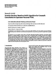
Similarly, we get (8) from [16, 17]. They represent the communication cycle time for POWERLINK and PROFINET protocol, respectively: 𝑇Cycle1 = 𝑇STA + 𝑁devices ∗ (𝑇SQ + 𝑇QS + 2 ∗ 𝑇frame ) + 𝑇master process , 𝑇Cycle2 = 𝑁devices
(8)
∗ (𝑇medium + 𝑇pn fwd + 𝑇frame ) + 𝑇masterprocess . The other typical index values in (7) and (8) are given as follows: 𝑇ecat fwd : the forwarding delay time whose value is 2.7 𝜇s; 𝑇STA : the duration of the start period with typical value 45 𝜇s; 𝑇SQ : the time elapsed between the reception of a poll responses frame by the MN and the instant the Poll Requests frame is issued to the next CN and defined as 1 𝜇s [16]; 𝑇QS : the time employed by a CN to send a poll responses frame after the arrival of the Poll Requests from the MN with value 8 𝜇s [16]; 𝑇pn fwd : the forwarding delay time which value is 3 𝜇s [17]. Figure 11 shows a diagram, whose compares the cycle time of EtherCAT, POWERLINK, and PROFINET as a function of the device amount. The diagram presents that the cycle time for EtherCAT protocol is smaller. And as the devices increase, the EtherCAT network cycle time increment is the least. When the devices increase from 1 to 10, the increment for EtherCAT protocol is only 28.75 𝜇s. However, the incremental values are 265.32 𝜇s and 121.2 𝜇s for POWERLINK and PROFINET protocol, respectively. 4.2.2. Data Throughput and Time Synchronization Accuracy. For this kind of network motion control system of ocean
wave maker, all of the wave making boards often need to be simultaneously impeled. In other words, it would be better to send all of control commands and data in one frame by master station. And then it is received and executed by all of the slave stations at the same time, which need network protocol with high throughput and time synchronization accuracy. The data exchange method of EtherCAT protocol, using the summation frame, can access a large amount of slave devices over one standard Ethernet frame. So the data throughput can be up to 90% [26]. Considering the minimum cycle time, the reference [28] gives the throughput comparison results between EtherCAT and POWERLINK. It is obvious that the EtherCAT protocol is superior to POWERLINK protocol. Furthermore, time synchronization accuracy can be up to 15 ns for the EtherCAT. The measured value by oscillograph is given in [30] whereas time synchronization accuracy of the other two protocols reaches only 1 𝜇s [31, 32]. 4.3. Experiment Results. We have tested the constructed networked wave maker control system which consists of 10 slave stations in three aspects. We adopt the system making regular sinusoidal wave and irregular wave, respectively, in the experiment shallow water pool. A series of regular sinusoidal data and irregular wave data are sent by the upper master station application program. The regular wave is a sinusoidal periodic signal with period 1 second and 6 cm wave height. And the irregular wave’s averaged wave height is 6 cm. The wave height is known as the variance between the maximum value and the minimum one of the wave height curve in wave theory. Figure 12 depicts the typical wave sensor feedback signals collected by the master station from 1# sensor, 16# sensor, 65# sensor, 145# sensor, and 160# sensor. As we can see in Figure 6, these sensors are linked to the 1# slave station, 5# slave station, and 10# slave station, respectively. Similarly, we make the irregular wave and the results are shown in Figure 13. The two diagrams of Figure 12 and Figure 13 show that the collected signal curves are smooth enough. Therefore, the system can meet making wave experiment needs. Next, in order to validate the system communication performance, we have written program code to measure the cycle time. These codes implement the cycle time calculating and are inserted into the main application program. After the data frame with acquired data and servo control commands is sent by the master station, the timer starts until the data frame with the collected sensor data comes back to the master station. In order to illustrate clearly the advantage of EtherCAT, we tested the system with varying number of slave stations. The results are shown in Figure 14. The results show that the system including a different number of slave stations has almost the same average communication cycle time. But the average communication cycle time concentrates on about 250 𝜇s. The delay time is very small when the data frame passes through the slave station node. The results agree with the theoretical analysis in Section 4.2. The value can be omitted in our system. Moreover, we analyzed 10 groups of cycle time values and calculated the average values.
13 Wave height (cm)
Wave height (cm)
International Journal of Distributed Sensor Networks 6
4 2 0 0
1
2 Wave period (s)
3
6
4 2 0 0
4
Wave height (cm)
Wave height (cm)
6
4 2 0 1
2 Wave period (s)
3
0
4
Wave height (cm)
Wave height (cm)
4 2 0 2 Wave period (s)
3
0
4
2 0 2 Wave period (s)
3
4
Wave height (cm)
Wave height (cm)
4
Wave height (cm)
Wave height (cm)
4 Wave period (s)
6
4 Wave period (s)
6
4 Wave period (s)
6
6
4 2 0
0
2 16# sensor
6
4 2 0 1
2
8
16# sensor
0
6
65# sensor
6
1
4 Wave period (s)
8 6 4 2 0
65# sensor
0
2 145# sensor
6
1
6
8 6 4 2 0
145# sensor
0
4 Wave period (s)
160# sensor
160# sensor
0
2
2 Wave period (s)
3
4
1# sensor
Figure 12: Regular wave height data signals from field sensors.
These values are depicted in Figure 15, which indicate that the maximum delay jitter is only 3.42 microseconds. The communication system can meet high-speed motion control requirement.
5. Conclusions The paper introduced the design of a typical networked motion control system based on EtherCAT protocol. This
8 6 4 2 0
0
2 1# sensor
Figure 13: Irregular wave height data signals from field sensors.
networked motion control system with large amount of measurement sensors asks for not only achieving real-time motion control but also transferring numerous sensor signals by less than 1 millisecond communication cycle time. So far, dozens of Industry Ethernet protocols have been released. Different from other Industry Ethernet protocols, EtherCAT protocol possesses high communication speed and efficiency
International Journal of Distributed Sensor Networks
Frame cyclic time (𝜇s)
Frame cyclic time (𝜇s)
Frame cyclic time (𝜇s)
14 450 400 350 300 250 200 150 100 50 0
450 400 350 300 250 200 150 100 50 0
450 400 350 300 250 200 150 100 50 0
e system including 10 slave stations
0
200
400 600 800 Number of data frames
1000
e system including 2 slave stations
0
200
400 600 800 Number of data frames
1000
e system including 1 slave station
0
200
400 600 800 Number of data frames
1000
Figure 14: Cycle time of the system connected 1 slave station, 2 slave stations, and 10 slave stations, respectively.
networked motion control system mentioned. The results of this study would be helpful for the design of the networked motion control system with large-capacity data acquisition which requires high efficiency and high real-time.
e mean values of cycle time (𝜇s)
260.0
259.5 259.0 258.5
Conflict of Interests
258.0
The authors declare that there is no conflict of interests regarding the publication of this paper.
257.5 257.0
Acknowledgments
256.5 256.0
0
2 4 6 8 e order number of sample groups
10
Figure 15: Average cycle time of system with 10 slave stations.
due to the specific communication principle. In particular, unparalleled hardware structure of slave interface controller makes the communication delay up to less than dozens of microseconds. Based on the test by control system platform, the experimental results show that EtherCAT protocol is the most suitable communication protocol for the type of
The paper is supported by Educational Commission of Henan Province of China (no. 2010A520020), National Natural Science Foundation of China (no. 51174263), Key Science and Technology Project of Henan Province (no. 112102210004), and Ph.D. Programs Foundation of Ministry of Education of China (20124116120004).
References [1] K. C. Lee, S. Lee, and H. H. Lee, “Implementation and PID tuning of network-based control systems via Profibus polling network,” Computer Standards and Interfaces, vol. 26, no. 3, pp. 229–240, 2004.
International Journal of Distributed Sensor Networks [2] N. P. Mahalik and A. N. Nambiar, “Trends in food packaging and manufacturing systems and technology,” Trends in Food Science and Technology, vol. 21, no. 3, pp. 117–128, 2010. [3] I. Erturk, “A new method for transferring CAN messages using wireless ATM,” Journal of Network and Computer Applications, vol. 28, no. 1, pp. 45–56, 2005. [4] A. Flammini, P. Ferrari, E. Sisinni, D. Marioli, and A. Taroni, “Sensor interface: from field-bus to ethernet and internet,” Sensors and Actuators A, vol. 101, no. 1-2, pp. 194–202, 2002. [5] A. Abarca, M. de la Fuente, J. M. Abril, A. Garc´ıa, and F. P´erez-Oc´on, “Intelligent sensor for tracking and monitoring of blood temperature and hemoderivatives used for transfusions,” Sensors and Actuators A, vol. 152, no. 2, pp. 241–247, 2009. [6] A. Flammini, P. Ferrari, D. Marioli, E. Sisinni, and A. Taroni, “Wired and wireless sensor networks for industrial applications,” Microelectronics Journal, vol. 40, no. 9, pp. 1322–1336, 2009. [7] J. Jasperneite, M. Schumacher, and K. Weber, “Limits of increasing the performance of industrial ethernet protocols,” in Proceedings of the 12th IEEE International Conference on Emerging Technologies and Factory Automation (ETFA ’07), pp. 17–24, Institute of Electrical and Electronics Engineers, Patras, Greece, September 2007. [8] B. Tao, H. Ding, and Y. L. Xiong, “Design and implementation of an embedded IP sensor for distributed networking sensing,” Sensors and Actuators A, vol. 119, no. 2, pp. 567–575, 2005. [9] S. Pal and A. Rakshit, “Development of network capable smart transducer interface for traditional sensors and actuators,” Sensors and Actuators A, vol. 112, no. 2-3, pp. 381–387, 2004. [10] L. Bissi, P. Placidi, A. Scorzoni, I. Elmi, and S. Zampolli, “Environmental monitoring system compliant with the IEEE 1451 standard and featuring a simplified transducer interface,” Sensors and Actuators A, vol. 137, no. 1, pp. 175–184, 2007. [11] J.-D. Kim, J.-H. Lee, Y.-K. Ham, C.-H. Hong, B.-W. Min, and S.-G. Lee, “Sensor-Ball system based on IEEE 1451 for monitoring the condition of power transmission lines,” Sensors and Actuators A, vol. 154, no. 1, pp. 157–168, 2009. [12] R. Dorschner, “Digital servo drives and SERCOS simplify machine installation, optimize performance,” Control Solutions, vol. 73, no. 10, pp. 50–54, 2000. [13] “Ethernet-driven motion control goes on a real bender,” Process and Control Engineering, vol. 59, pp. 21–23, 2006. [14] H. Makete, “Real-time requirements for discrete time applications in automation systems,” Elektron, vol. 22, no. 3, pp. 36–40, 2005. [15] P. Ferrari, A. Flammini, and S. Vitturi, “Performance analysis of PROFINET networks,” Computer Standards and Interfaces, vol. 28, no. 4, pp. 369–385, 2006. [16] G. Cena, L. Seno, A. Valenzano, and S. Vitturi, “Performance analysis of Ethernet Powerlink networks for distributed control and automation systems,” Computer Standards and Interfaces, vol. 31, no. 3, pp. 566–572, 2009. [17] J. Jasperneite, M. Schumacher, and K. Weber, “Limits of increasing the performance of industrial ethernet protocols,” in Proceedings of the 12th IEEE International Conference on Emerging Technologies and Factory Automation (ETFA ’07), pp. 17–24, September 2007. [18] L. Seno and S. Vitturi, “A simulation study of Ethernet powerlink networks,” in Proceedings of the 12th IEEE International Conference on Emerging Technologies and Factory Automation (ETFA ’07), pp. 740–743, September 2007.
15 [19] K. W. Song and G. S. Choi, “Fieldbus based distributed servo control using LonWorks/IP gateway/web servers,” Mechatronics, vol. 20, no. 3, pp. 415–423, 2010. [20] L. Wang, P. Orban, A. Cunningham, and S. Lang, “Remote realtime CNC machining for web-based manufacturing,” Robotics and Computer-Integrated Manufacturing, vol. 20, no. 6, pp. 563– 571, 2004. [21] M. Rostan, J. E. Stubbs, and D. Dzilno, “EtherCAT enabled advanced control architecture,” in Proceedings of the IEEE/SEMI Advanced Semiconductor Manufacturing Conference (ASMC ’10), pp. 39–44, July 2010. [22] B. A. GmbH, “Hardware Data Sheet ET1100—EtherCAT Slave Controller, Vel’. 1. 8,” 2008, http://www.beckhoff.com. [23] G. Prytz and J. Skaalvik, “Redundant and synchronized EtherCAT network,” in Proceedings of the 5th International Symposium on Industrial Embedded Systems (SIES ’10), pp. 201–204, IEEE Computer Society, Trento, Italy, July 2010. [24] M. Rehnman and T. Gentzell, “Synchronization in a force measurement system using EtherCAT,” in Proceedings of the 13th IEEE International Conference on Emerging Technologies and Factory Automation (ETFA ’08), pp. 1023–1030, Institute of Electrical and Electronics Engineers, Hamburg, Germany, September 2008. [25] G. Cena, I. C. Bertolotti, S. Scanzio, A. Valenzano, and C. Zunino, “On the accuracy of the distributed clock mechanism in EtherCAT,” in Proceedings of the IEEE International Workshop on Factory Communication Systems (WFCS ’10), pp. 43–52, Institute of Electrical and Electronics Engineers, Nancy, France, May 2010. [26] G. Cena, S. Scanzio, A. Valenzano, and C. Zunino, “Performance evaluation of the EtherCAT distributed clock algorithm,” in Proceedings of the IEEE International Symposium on Industrial Electronics (ISIE ’10), pp. 3398–3403, Institute of Electrical and Electronics Engineers, Bari, Italy, July 2010. [27] J. C. Lee, S. J. Cho, Y. H. Jeon, and J. W. Jeon, “Dynamic drift compensation for the distributed clock in EtherCAT,” in Proceedings of the IEEE International Conference on Robotics and Biomimetics (ROBIO ’09), pp. 1872–1876, IEEE Computer Society, Guilin, China, December 2009. [28] L. Seno, S. Vitturi, and C. Zunino, “Real time ethernet networks evaluation using performance indicators,” in Proceedings of the IEEE Conference on Emerging Technologies and Factory Automation (ETFA ’09), September 2009. [29] L. Winkel, “Real-time ethernet in IEC 61784-2 and IEC 61158 series,” in Proceedings of the IEEE International Conference on Industrial Informatics (INDIN ’06), pp. 246–250, Institute of Electrical and Electronics Engineers, Singapore, August 2006. [30] EtherCAT Technology Group, http://www.ethercat.org/. [31] “Real-Time PROFINET IRT,” http://www.profibus.com/. [32] Ethernet Powerlink Standardization Group, http://www.ethernet-powerlink.org/.
International Journal of
Rotating Machinery
Engineering Journal of
Hindawi Publishing Corporation http://www.hindawi.com
Volume 2014
The Scientific World Journal Hindawi Publishing Corporation http://www.hindawi.com
Volume 2014
International Journal of
Distributed Sensor Networks
Journal of
Sensors Hindawi Publishing Corporation http://www.hindawi.com
Volume 2014
Hindawi Publishing Corporation http://www.hindawi.com
Volume 2014
Hindawi Publishing Corporation http://www.hindawi.com
Volume 2014
Journal of
Control Science and Engineering
Advances in
Civil Engineering Hindawi Publishing Corporation http://www.hindawi.com
Hindawi Publishing Corporation http://www.hindawi.com
Volume 2014
Volume 2014
Submit your manuscripts at http://www.hindawi.com Journal of
Journal of
Electrical and Computer Engineering
Robotics Hindawi Publishing Corporation http://www.hindawi.com
Hindawi Publishing Corporation http://www.hindawi.com
Volume 2014
Volume 2014
VLSI Design Advances in OptoElectronics
International Journal of
Navigation and Observation Hindawi Publishing Corporation http://www.hindawi.com
Volume 2014
Hindawi Publishing Corporation http://www.hindawi.com
Hindawi Publishing Corporation http://www.hindawi.com
Chemical Engineering Hindawi Publishing Corporation http://www.hindawi.com
Volume 2014
Volume 2014
Active and Passive Electronic Components
Antennas and Propagation Hindawi Publishing Corporation http://www.hindawi.com
Aerospace Engineering
Hindawi Publishing Corporation http://www.hindawi.com
Volume 2014
Hindawi Publishing Corporation http://www.hindawi.com
Volume 2014
Volume 2014
International Journal of
International Journal of
International Journal of
Modelling & Simulation in Engineering
Volume 2014
Hindawi Publishing Corporation http://www.hindawi.com
Volume 2014
Shock and Vibration Hindawi Publishing Corporation http://www.hindawi.com
Volume 2014
Advances in
Acoustics and Vibration Hindawi Publishing Corporation http://www.hindawi.com
Volume 2014