In this paper we introduce a bootstrapping technique allowing us to translate ... microcode and assembly level code generation, we propose a bootstrapping.
Retargetable Assembly Code Generation by Bootstrapping Rainer Leupers, Wolfgang Schenk University of Dortmund, Lehrstuhl Informatik 12 D-44221 Dortmund, Germany Report No. 488 July 1993
ABSTRACT In a hardware/software codesign environment compilers are needed that map software components of a partitioned system behavior description onto a programmable processor. Since the processor structure is not static, but can repeatedly change during the design process, the compiler should be retargetable to avoid manual compiler adaption for any alternative architecture. A restriction of existing retargetable compilers is that they only generate microcode for the target architecture instead of machine-level code. In this paper we introduce a bootstrapping technique allowing us to translate high-level language (HLL) programs into real machine-level code using a retargetable microcode compiler. The retargetability is preserved, permitting to compare di�erent architectural alternatives in a codesign framework within relatively little time. As an application of the new code generation technique we consider hardware/software codesign of heterogeneous information processing systems. i
Contents 1 2 3 4 5 6 7 8 9
Introduction Microcode Generation in the MIMOLA Software System Bootstrapping Approach Micro-ROM Generation Machine Code Generation Code Example Hardware/Software Codesign for Heterogeneous Systems Exploring Architectural Alternatives Conclusions
ii
1 3 6 8 10 12 14 15 18
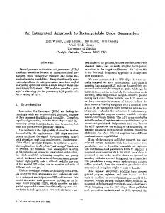
1 Introduction The "hardware/software codesign" approach increasingly gains importance in digital system synthesis from behavioral descriptions. Codesign means partitioning an abstract behavioral description into hardware and software components forming a system with the speci ed behavior and meeting given timing restrictions. Especially it supports design of digital controllers performing real-time computations. The target architecture might be a simple system containing a programmable processor, a main memory, and several ASICs, as proposed in [1] ( g. 1). MICROPROCESSOR CORE 6 �
-
�
-
?
'$ &% '$ &% ASIC
ASIC
MEMORY
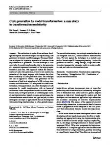
Figure 1: System Architecture There, software components of the partitioned description are executed on the processor (core), whereas real-time routines are performed by ASICs (the hardware components of the partitioned description). Additionally the processor controls component communication that is done using a central bus. A standard processor as well as a processor core may be used. Especially in the DSP domain a very simple core may su�ce, since DSP systems typically perform short, arithmeticintensive tasks. In case that arithmetical subtasks are done by ASICs, the smallest possible core should be chosen, that can execute the necessary software components still allowing other hardware modules to be put onto the same chip. Complex behavioral descriptions might require extended target architectures, e.g. more than one core and local component communication, but the simple model depicted in g. 1 su�ces for studying general requirements on codesign tools. Since communication overhead implied by a certain system partition is hardly predictable, codesigning a digital system requires several iteration steps in general ( g. 2). During the iteration the necessary hardware and software components change, causing di�erent core 1
requirements in each step. In order to simulate the system behavior for a given hardware/software partition the hardware components have to be synthesized and the software components have to be mapped onto the core. For the latter a compiler is needed that translates an HLL program into the core instruction set. Commercial compilers are available for some standard processors but never for special cores. Therefore we recommend using a retargetable compiler, processing both an HLL program and a processor (core) description, and producing machine code for the described hardware. The compiler retargetability enables the designer to study di�erent core alternatives without manually changing the compiler itself.
� �
� � �
BEHAVIORAL DESCRIPTION
� ��
?
HH H H j
SW COMPONENTS
�� � � �� � � � � ?
HW SYNTHESIS @ @ R @
�
PARTITIONING
HW COMPONENTS
� �
� �
?
COMPILATION
SIMULATION OK
?
STOP
� /
�
NOT OK
Figure 2: HW/SW Codesign Flow Several retargetable compilers are mentioned in the literature [2, 3, 4], among them our code generator MSSC. MSSC takes both a target structure description and a PASCAL program emitting binary code automatically, that executes the PASCAL program on the given structure if possible. A disadvantage of those compilers (when using it in a codesign environment) is that only code for the lowest programming level is generated, i.e. microinstructions. if only the processor datapath but not the controller is to be changed, the core still must be programmed in (assembly-level) machine code. Generating machine code is not provided by the above compilers. The GNU C Compiler [5], which is also regarded to be retargetable, generates assembly level code, but retargeting requires a large amount of translation directives and recompiling for each target machine. MSSC generates code from the pure RT-level machine description and therefore needs not to be recompiled. To ll the gap between microcode and assembly level code generation, we propose a bootstrapping technique enabling the designer to translate an HLL program into machine code using an existing retargetable microcode compiler. Using this technique makes the microcode compiler a useful tool 2
in a codesign framework. Di�erent processor datapaths implying di�erent machine instruction sets can be tried during the design iteration without compiler adaption, still allowing the designer to specify software components in high-level language, and thus accelerating evaluation of a certain system partition. The approach even may be used for standard processors, when no target-speci c compiler is available although this is not its main purpose. We describe the bootstrapping approach using the TMS320C25 as an example, a widely-spread standard DSP. The compiler MSSC itself has been described elsewhere [6, 7], so only a short overview is given in the following section. After that the basic bootstrapping idea is explained, followed by a detailed description of the two main steps (micro-ROM generation and machine code generation). An example for generated machine-level code is given in section 6. Finally it is shown how the new code generation technique can be applied for hardware/software codesign of heterogeneous systems. The paper ends with a conclusion.
2 Microcode Generation in the MIMOLA Software System The retargetable microcode generator MSSC is part of the MIMOLA Software System (MSS), which supplies hardware synthesis, generation of self-test programs, simulation and schematics generation, too [10, 11]. Every MSS tool is based on the MIMOLA language that allows both hardware and software descriptions. Hardware descriptions contain RT modules, their behavior and their interconnections. For instance, a 32 bit ALU might be speci ed in MIMOLA as follows: MODULE ALU (IN a, b : (31:0); OUT outp: (31:0); FCT ctr : (1:0)) BEGIN outp ALU.a; ALU.outp
-> ACCU.inp;
3
Software descriptions in MIMOLA may consist of PASCAL statements, but RT-level programming is supported, too. All high-level control structures (FOR, WHILE, REPEAT,...) are supplied, but there are no prede ned data types. They can be declared by bitstrings, e.g. by TYPE Integer = (15:0);
De nition of complex data types (ARRAY, RECORD) is supported, e.g. the user could declare TYPE ArrType = ARRAY [1..10] OF Integer;
Hardware and software description together form the input to MSSC, that translates the given program into microinstructions for the given programmable hardware structure ( g. 3). MSSC has been described in detail in [6, 7], we only give a rough summary of the four main steps here.
SW Description HW Description BEGIN WHILE a0 THEN ...
ADD : 0110X010010X CMPL:110XX0X10010 LAR : 100X010110X0 micro-ROM -
PASCAL Program
MSSC
�
?
21: 0100000100000010 (ZALS 2) 22: 1100110000000001 (ADDK 1) 23: 0110000000000011 (SACL 3) Assembly Instructions
Figure 4: Basic Idea of Bootstrapping
6
Phase 1 (Micro-ROM generation) 1. Hardware structure modelling: The target processor's RT-structure is described in MI-
MOLA, containing the datapath, storage modules as well as a simple microcontroller that uses separate control lines for every module. This controller is dropped in the second phase and does not need to be structurally identical to the real controller. Therefore, when modelling the target processor the designer only needs knowledge about the datapath and storage/register modules. This information can be taken for example from a processor data book, whereas information about the controller usually is not provided.
2.
3.
Assembly instruction modelling: The RT-level behavior of available assembly instruc-
tions is modelled in MIMOLA. The result is a "program" that simply consists of a listing of all assembly instruction behaviors. This "program" forms the software description for the rst MSSC run.
Micro-ROM generation: The compiler MSSC is applied to the hardware description and
to the "program" containing the assembly instruction behaviors. For technical reasons we assume every machine instruction to be executable within a single cycle. As described later, this means no restriction, however. Thus MSSC generates a microprogram in which each microinstruction corresponds to a realisation of a certain assembly instruction. The microprogram is stored into the declared instruction memory. Since this memory is not part of the real target hardware, it is a kind of "virtual" micro-ROM. Note that successful micro-ROM generation implies verifying the hardware description, i.e. the structure is able to execute the speci ed machine instructions. Therefore, "correctness by construction" is guaranteed. This feature of our approach may also be used to easily obtain a correct processor model for simulation purposes.
Phase 2 (Machine code generation) 1. Controller replacement: The micro-ROM generated in phase 1 is now assumed to be
part of the target hardware structure. All control lines still radiate from the micro-ROM that simply serves as a decoder here. By addressing a line in the micro-ROM execution of a certain machine instruction can be selected. Addressing the micro-ROM is now done from the "real" machine instruction memory which in its turn is addressed by the "real" machine-level program counter. As mentioned in section II, MSSC is able to produce binary code for controlling modules via decoders. Since every module only can be controlled via the micro-ROM, and the micro-ROM only contains microcode for machine instructions, MSSC is forced to generate encoded machine instructions when applied to the structure and an HLL program.
2.
HLL program translation: Now the same hardware structure as in phase 1 serves as an
input to MSSC, extended by the micro-ROM. The software description in principle could be any HLL (PASCAL in our case) program. MSSC produces binary code in which every 7
instruction contains an address for the micro-ROM (and thus an encoded machine instruction) as well as necessary operands. This binary code can be easily transformed to real machine code using a table. The result is an assembly-level machine program for the target processor realising the given HLL program.
?
+1
MPC
6
?address
MIS ...
-
.. . -
control lines
Figure 5: Simple Controller in Phase 1 For a given target processor, phase 1 has to be performed only once. After that any PASCAL program can be translated into machine code by a single call of MSSC. Both phases are described in detail in the two following sections. For better understanding of the bootstrapping technique, we consider the digital signal processor TMS320C25 as an example.
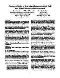
4 Micro-ROM Generation In phase 1 a micro-ROM is to be generated, in which every control word realises exactly one machine instruction. At rst the target structure (here: TMS320C25) has to be modelled. Most of the datapath structure can be found in [12] and can be written as a MIMOLA hardware description. Information about the internal controller structure is not available in [12], but this causes no problems since we only need a simple microcontroller structure for phase 1. The MIMOLA model of the TMS contains about 2000 text lines. The model needs not to be exactly equal to the real hardware, the crucial point is that modelled hardware is able to perform the desired machine instructions. This simpli es the modelling phase, especially if only a rough datapath description is available to the user. The TMS contains a 16 bit program counter and a 4k program ROM. These modules are modelled, too, but not according to their real functionality in the rst phase. Instead we use the simple controller shown in g. 5. The microinstruction storage (MIS) controls all but the residual control 8
modules directly. Its wordlength is 150 bits in our model. It is addressed by a microprogram counter (MPC) which is incremented after each cycle. MPC and incrementer are only used for micro-ROM generation, since MSSC always needs a program counter and at least an incrementer for compilation. Both modules are unimportant for the further steps. The software input for MSSC is a "program" which simply enumerates all assembly instructions and their RT-level behavior (in MIMOLA). This information can also be taken from [12]. The "program" looks as follows: PROGRAM InstructionSet IS LABEL ADDK, CMPL, ... BEGIN ADDK: (* add to accu short immediate *) PARBEGIN ACC := ACC + ZeroExtend24(PgmROM[PC].(7:0)); PC := "INCR" PC; PAREND; CMPL: (* complement accumulator *) PARBEGIN ACC := "NOT" ACC; PC := "INCR" PC; PAREND; END;
This extract shows how the behavior of two simple assembly instructions might be modelled in MIMOLA. For every instruction a label of the same name is declared. The ADDK instruction adds an 8 bit constant from the instruction word in the program ROM (addressed by the real program counter PC) extended by 24 zero bits to the accumulator and stores the result into the accumulator again. The PC is incremented in parallel. The CMPL instruction inverts the accumulator and can be modelled similarly. This "program" is mapped onto the target structure by MSSC. It is never executed, only the resulting binary code is important. Since no branches occur, the incrementer ( g. 5) is su�cient for modifying the MPC. The generated microcode is stored into MIS, containing a sequence of 150 bit microinstructions then. Each microinstruction corresponds to a machine instruction ( g. 6). MIS contains as many lines as machine instructions have been speci ed, because a suitable hardware model guarantees that only single-cycle instructions are generated. The initialised MIS is used as one MSSC input in the second phase. It contains the information about available machine instructions and their implementation by microinstructions. 9
.....
149
0
0100............................0X11 (ADDK) 10X0............................1101 (CMPL) X011............................0010 (LARP)
further instructions>