Reverse Engineering of OO constructs in Object-Relational Database Schemas Jordi Cabot1 , Cristina Gómez2 , Elena Planas 1 and M.Elena Rodríguez1 1
Estudis d'Informàtica, Multimèdia i Telecomunicació, Universitat Oberta de Catalunya {jcabot,eplanash,mrodriguezgo}@uoc.edu 2 Dept. Llenguatges i Sistemes Informàtics, Universitat Politècnica de Catalunya
[email protected]
Abstract. Reverse engineering applied to databases permits to extract a conceptual schema that represents, at a higher level of abstraction, the database implementation. This resulting conceptual schema may be used to facilitate, among others, system maintenance, evolution and reuse. In the last years, the use of object-relational constructs was incorporated into database development. However, reverse engineering techniques for these specific constructs have not been yet provided. In this sense, the main goal of this paper is to present a method that considers these new constructs in the reverse engineering of an existing object-relational database. As a result of the process, our method returns an equivalent conceptual schema specified in UML (extended with a set of OCL integrity constraints) that represents, at a conceptual level, the database schema. We provide a prototype tool that implements our method for the Oracle9i database management system.
Keywords: Reverse Engineering, Object-relational database, UML
1 Introduction Software reverse engineering is the process of analyzing a subject system to identify its components and their interrelationships and to create representations of the system in another form or at higher level of abstraction [1]. Reverse engineering applied to databases (DB) permits to obtain a conceptual schema (CS) that represents, at a higher level of abstraction, a DB implementation. This CS may be helpful in several situations. For instance, when documenting the system to ease its maintainance and evolution. Usually, changes on the DB schema (DBS) are poorly documented once the DB has been created. Therefore, reverse engineering of the DBS from time to time is needed to keep its documentation up to date. The CS also facilitates sytem integration and reuse. The integration process requires data understanding of the systems to be integrated. This data understanding is better achieved when we raise its abstraction level to omit all implementation details, as done during the DB-to-CS transformation. Reverse Engineering has received a lot of attention during the last decades in the DB field [2], [3]. For relational databases, several processes have been defined to extract a conceptual object model from a relational one. Concretely, [4] presents a flexible and interactive approach to obtain an OMT model [5] with classes, associations, generalizations and key and referential constraints from a relational DBS. In the same way, [6] states a method for translating a relational DBS to an ORM [7] model instance. Some work has also been done in the context of OODBs. [8] defines a series of transformations to derive an OMT model from the source code of an existing OO system with an underlying OODB. [9] proposes a process of rebuilding an abstract documentation of the
object classes with attributes, inheritance hierarchies and methods which are declared and manipulated in OO application programs. Nevertheless, although techniques for forward engineering of Object-Relational databases (ORDB) have been developed [10], [11], as far we know, reverse engineering for ORDB has not been addressed. Given that most vendors (as Oracle or IBM) and open source DBs (as PostgreSQL) incorporate nowadays OO constructs in their flagship products, we believe that specific methods for reverse engineering of ORDBs are required, especially because these new OO constructs (combined with the previous relational constructs) introduce multiple alternatives in DB design, alternatives that must be considered when reverse engineering this kind of databases. The main goal of this paper is to present a new method to obtain a UML-based conceptual schema representation (UML 2.1 [12]) of a given object-relational database schema (ORDBS). When appropriate, this UML schema is extended with a set of OCL integrity constraints [13]. Our method is composed of different steps, where each step tackles the transformation of some of the OO constructs that may appear in an ORDBS. In this paper, we only consider the reverse engineering of these constructs since, as we mention above, reverse engineering for relational database constructs has been deeply studied in the literature, and thus, our method can be regarded as an extension of these previous ones. Note that, even if OO constructs in ORDBs seem similar to those in object-oriented databases, they cannot be directly compared (the first ones have been designed to be compatible with the relational model while the second ones with OO programs). Therefore, a specific method for ORDBs must be developed. Additionally, we provide a prototype tool that implements our reverse engineering method for the Oracle9i database management system (DBMS) one of the relational DBMS that best supports these new OO constructs. The rest of the paper is structured as follows. Section 2 presents the OO constructs admitted by the SQL:1999 plus the additional ones provided in the Oracle9i DBMS. Section 3 presents an overview of our method. The transformation rules for each construct and the refinement of the resulting CS are presented in sections 4 and 5. Section 6 presents the prototype. Some conclusions and future work are sketched in section 7.
2 OO constructs in ORDBSs Standard SQL, since SQL:1999 [14] offers a set of OO constructs that can be combined with classical relational constructs. SQL:2003, the latest version of standard SQL, maintains with few extensions these constructs. In this section we briefly examine some OO constructs, specifically we concentrate on those present in SQL:1999. The main OO characteristic is the possibility of defining complex types, i.e. types that have no directly associated atomic values. Such complex types can be collections or structured compound types. Both can be placed wherever a built-in SQL data type could be used such as, for example, in table column definitions. This contrasts with the classical relational data model which explicitly forbids this possibility, given that a table with decomposable columns violates first normal form. The SQL:1999 data type to specify collections is the ARRAY type; an ARRAY has a maximum cardinality and it can be built over any SQL:1999 data type except over another ARRAY type. For defining structured compound types, SQL:1999 offers the ROW type and the user defined types (UDTs). We only examine UDTs, given that ROW types could also be represented by means of UDTs. A UDT allows users to express new types, as complex as required, through the definition of their properties (attributes) and their intended behaviour (methods). In its turn, the type of a UDT’s attribute could be also a complex type. UDTs can be extended and/or redefined, i.e. they can participate in taxonomies. Then, we are able to indicate if they are instantiable, that is, whether new instances of the UDT can be created. An instance of a UDT is a set of values. To be objects (in OO paradigm), instances of UDTs must be stored as rows of typed tables, a new element of SQL:1999. A typed table is always based on a previously defined UDT. It can be seen
as a table having a single compound column (that follows the structure of its associated UDT), or as a table having as many columns as attributes the related UDT has. Rows of typed tables are globally unique identified. References between rows can be defined using the new REF type. Therefore, the REF type can be used for implementing relationships as an alternative to the use of foreign keys. With REF types we can navigate across DB objects, saving join operations needed when using foreign keys. SQL:1999 also allows table taxonomies. When a table is defined under its supertable, it inherits not only the column structure, but also integrity constraints, triggers, indexes, etc. Up to this point we have examined SQL:1999, we now comment on the OO constructs offered by commercial ORDBMSs. We will focus on Oracle, which is the commercial product that better fits (and extends) OO characteristics defined by SQL:1999, although there are slightly differences in nomenclature and syntax. ARRAY, UDTs and typed tables are respectively called, in Oracle, VARRAY, object types and object tables. REF type is also supported by Oracle. In addition to VARRAYs, Oracle also offers nested tables (not included in SQL:1999) for defining collections. A nested table is an unordered collection of elements of a given type; it can be used as a column data type in another table; therefore a nested table can be seen as a table embedded in another table. Table 2.1. Examples of OO constructs in Oracle. UDTs definitions -- Array of 2 phones CREATE TYPE phones_list IS VARRAY(2) OF INTEGER; -- New sybtypes from Address are not allowed CREATE TYPE Address AS OBJECT( street VARCHAR2(40), num INTEGER, floor VARCHAR(10), town VARCHAR(30), postal_code INTEGER )INSTANTIABLE FINAL; -- Type ref to Organizer CREATE TYPE Organizer_REF_VARRAY AS OBJECT( ref_Organizer REF Organizer )INSTANTIABLE FINAL; -- Array of 6 Organizers CREATE TYPE Organizer_REFS_VARRAY IS VARRAY(6) OF Organizer_REF_VARRAY; -- Type Checkpoint CREATE TYPE Checkpoint AS OBJECT( id INTEGER, description VARCHAR2(100), excursion_id INTEGER, supervised_by Organizer_REFS_VARRAY, MEMBER PROCEDURE set_information (id INTEGER, descr VARCHAR) )INSTANTIABLE FINAL; -- Person is an abstract type CREATE TYPE Person AS OBJECT( id INTEGER, dni VARCHAR2(9), name VARCHAR2(30), age INTEGER,
addr Address, mail VARCHAR2(30), MEMBER PROCEDURE set_mail (newMail VARCHAR2), MEMBER PROCEDURE incr_age )NOT INSTANTIABLE NOT FINAL; -- Type Organizer (Person subtype) CREATE TYPE Organizer UNDER Person( phone phones_list, supervises REF Checkpoint )INSTANTIABLE FINAL; -- Type Hiker (Person subtype) CREATE TYPE Hiker UNDER Person( ages_experience INTEGER, num_excursions INTEGER )INSTANTIABLE FINAL; Typed table definitions -- Table Checkpoint CREATE TABLE Checkpoint_OT OF Checkpoint( id PRIMARY KEY, description NOT NULL )OBJECT ID PRIMARY KEY; -- Table Person CREATE TABLE Person_OT OF Person( id PRIMARY KEY NOT NULL, name UNIQUE, CONSTRAINT check_age CHECK (age > 10) )OBJECT ID PRIMARY KEY; -- Table Organizer CREATE TABLE Organizer_OT OF Organizer; -- Table Hiker CREATE TABLE Hiker_OT OF Hiker;
Table 2.1 shows examples of the previous described constructs, according to Oracle9i syntax [15]. These examples intend to model data required for a hiking centre interested in storing data about its members and organized activities. We will use these examples to illustrate our reverse engineering method in the following sections. The complete case study can be found in the Appendix.
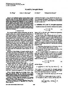
3 Method Overview Given a running ORDB, our method extracts its DBS and returns a possible equivalent CS specified in UML. By equivalent we mean that the CS and the DBS accept the same information (i.e., all data that can be stored in the DBS is a valid instantiation of the CS and conversely). We ensure this equivalence by choosing an appropriate construct in the CS for each element of the DBS. Our method consists of three different phases (Fig. 3.1). In the first one, the DBS is retrieved from the running ORDB by means of executing a set of predefined queries against the data dictionary. The second phase addresses the transformation of the OO constructs of this DBS and returns a preliminary UML CS. Finally, in the third phase, the user may optionally intervene in the process to refine and improve the obtained CS. By far, the main part of the reverse engineering process is carried out in the second phase. This second phase can be split up into the following basic transformation steps, where each step transforms a subset of the elements that may appear in the DBS. The transformation rules involved in each step are provided in the next section. The ordered list of steps is the following: 1. UDTs’ transformation: Each UDT gives rise to a class or data type in the CS. 2. Built-in data types transformation: Each data type is mapped to one of the predefined UML data types. 3. UDTs’ attributes transformation: Given an attribute of a UDT, our method may generate an attribute in a UML class or data type, an association, a composition or an association class, depending on the attribute characteristics. 4. UDTs’ methods transformation: Each UDT method produces a new method in the corresponding class or data type in the CS. 5. Constraints transformation: The constraints of the DBS bring about minimum association multiplicities and/or textual OCL integrity constraints in the CS. 6. Taxonomies creation: clauses UNDER and [NOT] INSTANTIABLE generate new generalization relationships in the CS. This ordering facilitates the creation of the CS (new elements are defined upon previously created ones), though alternative orderings could be used instead. We would like to remark that our method is not limited to the reverse engineering of SQL:1999 constructs; specific Oracle constructs are also considered. METHOD CS’ ORDBMS
1 DBS Extraction
Data Dictionary
UDTs
Bult-in Data Types
DBS
2 DBS Transformation
Attributes
Methods
CS
3 CS Refinement
Constraints
Fig 3.1. Method Overview.
Taxonomies
4 Transformation Rules In what follows we define the different transformation rules presented above. For each rule we describe its applicability conditions and include a transformation template that shows the DBS elements addressed by the rule and the corresponding UML elements, generated when processing the DBS with that particular rule. To indicate the elements of the DBS tackled by each rule, we show the SQL code excerpt (in Oracle9i syntax) that was used to create them in the running DB. See rule 1 for a more detailed explanation. The application of all rules over the whole case study introduced in section 2 is shown in Appendix. Due to space limitations, in this section we will just present some relevant examples. Table 4.1. Templates of a subset of Transformation Rules.
Rule 1
Rule 2
CREATE TYPE A AS OBJECT(); CREATE TABLE A_ot OF A;
CREATE TYPE B AS OBJECT();
Rule 4
Rule 5
CREATE TYPE A AS OBJECT( attr1 VARCHAR2(40), attr2 CHAR(9), attr3 INTEGER, attr4 DATE, attr5 NUMBER(2,2) ); CREATE TABLE A_ot OF A;
CREATE TYPE List IS VARRAY(n) OF basicType; CREATE TYPE A AS OBJECT( attr List ); CREATE TABLE A_ot OF A;
Rule 7
Rule 10
CREATE TYPE A AS OBJECT( attr B ); * Where A and B are clases
CREATE TYPE A AS OBJECT( attr B ); * Where A and B are clases
Rule 13
Rule 14
CREATE TYPE A AS OBJECT( attr B ); * Where A is a class and B is a data type
Rule 18
CREATE TYPE A AS OBJECT( MEMBER FUNCTION F1 RETURN Type, STATIC FUNCTION F2 (p Type) RETURN Type, MEMBER PROCEDURE F3 (p Type) ); * Where A is a class
Refinement (Transforming classes into associations)
CREATE TYPE B AS OBJECT(); CREATE TABLE B_ot OF B;
CREATE TYPE A UNDER B(); CREATE TABLE A_ot OF A;
4.1
UDTs’ transformation
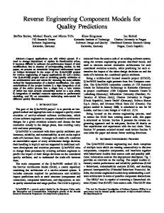
A UDT corresponds to either a class or a data type in the CS. As a criterion to distinguish both cases, we take into account whether the instances of the UDT may have an existence on their own or must always exist as part of another complex object. Rule 1. Each UDT associated with a typed table is transformed into a UML class. The template for this rule should be read as follows. If the DBS contains an arbitrary UDT A and there is a typed
table that uses that same UDT A as a base type then a UML class with the same name will be generated in the CS to represent both the UDT and the typed table. Rule 2. UDTs not appearing as the underlying type of any typed table are represented as data types in the CS.
Fig 4.1. Set of UML classes and data types resulting from the application of rules 1 and 2 over the DBS example shown in section 2.
4.2
Built-in Data Types transformation
A mapping between built-in data types in the DBS and the predefined set of data types permitted in the UML language must be determined before being able to proceed with the reverse engineering of the UDTs’ attributes. Rule 3. The correspondences between built-in data types in Oracle and the UML predefined types are: The Char(n) type is transformed into a String type with an additional OCL constraint over all attributes of that type stating that the length of their String value must be exactly n. The Varchar2(n) type is transformed into a String type with an additional constraint verifying that the maximum length of the String value is n. Integer, Float and Date types are transformed into their equivalents UML Integer, Real and Date types. The Number(precision,scale) is transformed into an Integer data type when precision is zero and into a Real type otherwise. 4.3
UDTs’ Attributes transformation
UDTs’ attributes may be represented by a variety of elements in the UML CS. The exact representation will depend on the complexity of the attribute (s imple, complex, REF) and cardinality (univalued or multivalued). Rule 4. Simple attributes of a UDT A are transformed into simple attributes of the class or data type corresponding to A in the CS (see rules 1 and 2). The type of the attribute in the CS is decided according to the rules seen in the previous section (plus the corresponding constraints). Rule 5. Attributes defined as a VARRAY of one of the built-in data types (VARRAY of Integer, Float, etc), are represented as multivalued attributes in the CS. Its minimum multiplicity is zero and its maximum one coincides with the VARRAY maximum length. Rule 6. Attributes defined as a nested table of a built-in data type are handled in the same way except for its maximum multiplicity which is now unlimited. Rule 7. A REF attribute defined in a UDT A (that has been transformed into a class) and referencing a UDT B (that has been transformed into a class) is represented by means of an association between A and B with a 0..1 multiplicity on the B role. Multiplicity on the A role is left undefined (at least for now). Later rules may provide additional information to precise the multiplicity. If not, * multiplicity is stated. The name of B role is the same as REF attribute name . Rule 8. When A contains an attribute that is a VARRAY of REFs to B, the association between A and B has as maximum multiplicity on the B role the one defined in the VARRAY. Rule 9. For nested tables of REF types, the maximum multiplicity is unlimited. Rule 10. When a UDT A (that has been transformed into a class) contains an attribute attr of type B and B has been previously transformed into a UML class in the CS, attr is represented as a composition relationship between A and B with a 0..1 multiplicity on the B role. A is the container, B the contained and B instances are related to exactly one A instance. With the composition
relationship we are able to link the lifespan of A instances with one of related B instances. As in rule 7, the name of B role is the same as attr of type B. Rule 11. When attr is a VARRAY of objects of type B then the composition association from A to B has as a maximum multiplicity on the B side the maximum length of the VARRAY. Rule 12. When attr is a nested table the maximum multiplicity is left unlimited. Rule 13. When the type of the attribute attr in A is the UDT B but B is represented as a data type in the CS, attr is kept as an attribute of the class corresponding to A.
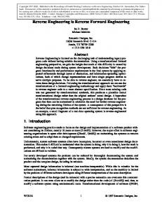
Fig 4.2. Subset of attributes and associations resulting from the application of rules 3 to 13 over the DBS example shown in section 2.
4.4
UDTs’ Methods transformation
Rule 14. Each method (including static methods) in the UDT is represented as a method in the data type or class in the CS (see rules 1 and 2) with the same signature. Currently, our method does not address the reverse engineering of the method body itself. 4.5
Constraints transformation
Typed tables may include several integrity constraints that restrict the possible values that the attributes of the underlying UDT may hold. All these constraints must also be included in the CS to ensure that the CS does not permit to instantiate objects with values that would be forbidden in the DBS. Rule 15. A NOT NULL constraint over an attribute is represented as a minimum 1-multiplicity in the corresponding element in the CS, either an attribute or an association (see section 4.3). Rule 16. UNIQUE and PRIMARY KEY constraints are represented as an OCL constraint in the CS. The context C of the new constraint is the class representing the UDT over which the typed table is defined. The body of the constraint is “C::allInstances()->isUnique(attr) ” where attr is the attribute marked as UNIQUE or PRIMARY KEY in the table. For UNIQUE or PRIMARY KEY constraints involving more than one attribute, the alternative constraint body should be used: “C::allInstances()->forAll(x,y| xy implies (x.att1y.att1 or … or x.att ny.attn)) ” where att1 …attn are the set of attributes restricted by the constraint. Rule 17. Each CHECK constraint generates a new OCL invariant (constraint) with the same expression in the constraint body (the expressivity allowed in the definition of CHECK constraints is rather limited and all possible operators have an equivalent counterpart with the same name in OCL). As an example, the OCL constraints generated for the example of section 2 are: context Checkpoint inv: Checkpoint.allInstances->isUnique(id) context Person inv: self.age > 10 context Person inv: Person.allInstances->isUnique(name) context Address inv: self.floor->size()isUnique(id) context Excursion inv: Excursion.allInstances ->isUnique(id) context Stage inv: Stage.allInstances->isUnique(id) context Checkpoint inv: Checkpoint.allInstances ->isUnique(id) context Checkpoint inv: self.description->size() isUnique(id) context Person inv: self.age > 10 context Person inv: Person.allInstances ->isUnique(name) context Person inv: self.mail->size() size() size() size() size() size()