2014 IEEE International Conference on Software Maintenance and Evolution
Reverse Engineering PL/SQL Legacy Code: An Experience Report Martin Habringer
Michael Moser and Josef Pichler
voestalpine Stahl GmbH 4020 Linz, Austria
[email protected]
Software Analytics and Evolution Software Competence Center Hagenberg GmbH 4232 Hagenberg, Austria
[email protected],
[email protected] x Changes in business cases over the last years were not reflected in verification logic of the legacy code.
Abstract—The reengineering of legacy code is a tedious endeavor. Automatic transformation of legacy code from an old technology to a new one preserves potential problems in legacy code with respect to obsolete, changed, and new business cases. On the other hand, manual analysis of legacy code without assistance of original developers is time consuming and errorprone. For the purpose of reengineering PL/SQL legacy code in the steel making domain, we developed tool support for the reverse engineering of PL/SQL code into a more abstract and comprehensive representation. This representation then serves as input for stakeholders to manually analyze legacy code, to identify obsolete and missing business cases, and, finally, to support the re-implementation of a new system. In this paper we briefly introduce the tool and present results of reverse engineering PL/SQL legacy code in the steel making domain. We show how stakeholders are supported in analyzing legacy code by means of general-purpose analysis techniques combined with domain-specific representations and conclude with some of the lessons learned. Keywords—reverse engineering; program source code analysis
x For a new production plant, additional requirements must be incorporated. x The maintenance of the legacy programs was complicated by the retirement of original developers. x Legacy code is not extensible in a safe and reliable way. x Stakeholders estimated high effort for manual analysis of the legacy code. The goal for the reverse engineering tool was to support stakeholders to comprehend the verification logic implemented in the legacy programs. Whereas, comprehension requires that stakeholders can (1) identify the business cases currently checked by the software as well as that stakeholders are able to (2) extend the verification logic with respect to new requirements.
comprehension;
The contributions of this paper are: 1) Presenting requirements for a reverse engineering tool aimed at PL/SQL legacy code.
I. INTRODUCTION Reengineering is the examination and alteration of a subject system to reconstitute it in a new form and the subsequent implementation of the new form [1]. Reengineering aims to improve the maintenance of software by combining three activities: reverse engineering to create representations of the system at a higher level of abstraction, re-structuring the highlevel representation, and forward engineering to move from high-level abstractions to the physical implementation of a system.
2) Introducing a tool that supports the analysis of PL/SQL legacy code. 3) Analyzing real-world legacy programs and providing insight into complexity, associated problems and lessons learned. II. PL/SQL LEGACY CODE The analysis presented in this paper has been performed on legacy programs that verify the production data within a steel plant (liquid phase and continuous casting). The programs analyze production data and detect errors such as inconsistency in data. The error correction is done by another system not considered here. The programs run on a daily/monthly/annual basis or occasionally after unexpected events.
For the reengineering of legacy programs that verify the consistency of production data in the steel making domain, we developed a reverse engineering tool to automatically generate high-level representations of the source code which facilitate the analysis of the legacy programs with respect to external behavior. The high-level representation serves as input for stakeholders to manually analyze the external behavior of the legacy programs, to identify obsolete and missing business cases, and, finally, for the re-implementation of a new system. The motivation for the selected reengineering approach is manifold: 1063-6773/14 $31.00 © 2014 IEEE DOI 10.1109/ICSME.2014.93
The programs are implemented in 286 stored procedures (127 kLOC), 8.088 tables, and ~600 Oracle reports. From this set, stakeholders classified 32 stored procedures (29 kLOC) as very relevant for the analysis because of their high density of
554 553
1: 2: 3: 4: 5: 6: 7: 8: 9: 10: 11: 12: 13: 14: 15: 16: 17: 18: 19: 20: 21: 22: 23: 24: 25: 26: 27: 28: 29: 30: 31: 32: 33: 34:
domain knowledge and their frequent use. The rest are special cases that run after idle state, time changes or as annual reports. The programs were originally developed by two experts on DB2 database software. Later, the programs were migrated to Oracle SQL scripts, and finally, migrated to Oracle PL/SQL programs. Both migrations were performed without checking the up-to-dateness of the implemented verification logic. The migration was done for technology reasons only and preserved the business cases during migration. So the external behavior of the current implementation in PL/SQL corresponds (more or less) to the original implementation given in DB2 database. In the current implementation, a stored procedure fetches production data and consolidates data into auxiliary tables (used by the stored procedure only). Then in a cascade of SQL statements, data are filtered and verified resulting in even more auxiliary tables and, finally, result tables, which are further processed by Oracle Reports to generate error reports for the users. Table I shows key data (lines of code, number of tables of production data, report data, auxiliary data) for the top ten stored procedures selected for reverse engineering (with respect to the total number of tables) as well as in total. TABLE I.
PROCEDURE P(...) BEGIN EXECUTE IMMEDIATE 'TRUNCATE TABLE AUXILIARY.T1'; INSERT INTO AUXILIARY.T1 SELECT A.COL1, A.COL2, A.COL3, B.COL1, B.COL2 FROM PRODUCTION.T1 A, PRODUCTION.T2 B WHERE A.COL1 = B.COL2; EXECUTE IMMEDIATE 'TRUNCATE TABLE AUXILIARY.T2'; INSERT INTO AUXILIARY.T2 SELECT A.COL1,A.COL2,A.COL3,A.COL4,A.COL5,B.COL2 FROM AUXILIARY.T1 A, PRODUCTION.T3 B WHERE A.COL1 = B.COL2; UPDATE AUXILIARY.T2 SET COL7 = 1 WHERE COL1 = COL4 OR COL2 < COL4; UPDATE AUXILIARY.T2 SET COL8 = 1 WHERE COL1 = ...; ... EXECUTE IMMEDIATE 'TRUNCATE TABLE REPORT.T1'; INSERT INTO REPORT.T1 SELECT 1, A.COL1, A.COL2, 42, 'Error X...' FROM AUXILIARY.T2 A WHERE COL7 = 1 UNION SELECT 1, A.COL1, A.COL2, 43, 'Error Y...' FROM AUXILIARY.T2 A WHERE COL8 = 1; END P;
KEY DATA OF PL/SQL STORED PROCEDURES
1 2 3 4 5 LOC 4.335 5.337 4.264 1.942 3.288 Production 49 30 16 5 12 Report 18 13 4 5 21 Auxiliary 153 140 140 130 107
6 715 8 1 62
7 8 9 850 1.254 1.001 10 14 11 1 7 7 53 30 32
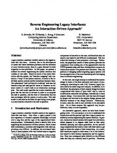
Fig. 1. A fragment of a PL/SQL program.
10 Total 466 29.349 4 216 2 132 29 1.036
III. THE PL/SQL REVERSE ENGINEERING TOOL A. Requirements When analyzing a program as shown in Fig.1, stakeholders are interested in errors which can be detected by the program and in the exact conditions of an error (i.e. the verification logic). In the example above, an error is detected in line 26 (error 'Error X...'), however, the corresponding condition is stated in line 18. In particular, the following requirements were identified to support stakeholders in analyzing legacy code:
A. PL/SQL Stored Procedure PL/SQL is a procedural extension of SQL, making it simple to write procedural code that includes SQL as if it were a single language. PL/SQL is most useful to write triggers and stored procedures. Stored procedures are units of procedural code stored in a compiled form within the database, in case of PL/SQL in an Oracle database. Fig. 1 shows a PL/SQL fragment of a stored procedure with a structure typical for the analyzed legacy code. A typical program is structured in the following way.
x Req#1. For all tables used by Oracle reports, the user has to understand the data source, either an external data from production data, a parameter of a stored procedure or a value (literal) generated by the stored procedure.
x Fetch of Production Data. Lines 4–8 fetch and store production data (schema name PRODUCTION) required for the verification. Lines 10–14 further filter data resulting in T2.
x Req#2. The extracted representation shall list all error codes generated by the verification logic. Error codes are sometimes meaningful error messages or just numbers or characters.
x Verification. After required data are collected, the actual verification is done, for instance by setting column values indicating an error under certain conditions (see lines 16–22). This is the actual verification logic stakeholders are interested in.
x Req#3. For every error code identified, stakeholders are interested in the actual verification logic of a single error. The verification logic shall be represented by a list of rules that can be analyzed in isolation from verification logic of other errors.
x Result. Lines 24–32 show how results from auxiliary tables (schema name AUXILIARY) are consolidated into result tables, that are finally analyzed by Oracle reports to generate error reports for users (schema name REPORT).
x Req#4. The verification logic shall be expressed by means of external data (i.e. production data or parameters) only. In other words, auxiliary tables must not be included in the result. Instead, the verification logic scattered over hundreds of SQL statements shall be traced back to production data only.
The first two steps may involve up to hundreds of SQL statements performed in sequence and up to hundreds of auxiliary tables.
554 555
B. Tool Overview To address the requirements presented in the previous section, we created a new tool to parse and analyze legacy PL/SQL code and to generate high-level representations.
PRO.T1
AUX.T1
AUX.T2
COL1 COL2 COL3
PRO.T1.COL1 PRO.T1.COL2 PRO.T1.COL3 PRO.T2.COL1 PRO.T2.COL2
PRO.T1.COL1 PRO.T1.COL2 PRO.T1.COL3 PRO.T2.COL1 PRO.T2.COL2 PRO.T3.COL1 COL7 COL8
PRO.T2
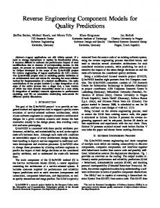
The tool is based on Metamorphosis [2], our toolkit for analyzing legacy systems in technical domains. Metamorphosis parses PL/SQL code and generates an abstract syntax tree specified by the ASTM (http://www.omg.org/spec/ASTM) meta-model defined by OMG. Based on the abstract syntax tree, the data flow from the production data to the result data containing error messages is analyzed. This analysis is based on well-known data flow analysis [3] and symbolic execution [4]. Traditional analysis techniques aim at procedural code only, hence, an extension with respect to SQL was necessary. Our core algorithm for the data flow analysis is an enhancement of the symbolic execution technique introduced for specification extraction [5]. With the SQL enhancements, we can trace the data flow from table to table and collect all filters (e.g. part of a WHERE clause) during data flow. The result of this analysis is then used to generate the expected high-level representation. This comprises different graphs (a schematic example is given in Fig. 2) for every program together with detailed HTML documents. Besides the PL/SQL code, the tool requires a database schema with meta-data about tables and columns. This meta-data is exported from the Oracle database and provided as comma-separated files to our tool.
REPORT.T1 ‘1‘ PRO.T1.COL3 PRO.T2.COL3 ‘42‘, ‘43‘ Error X, Error Y
COL1 COL2 COL3 COL4
PRO.T3 COL1 COL2
Fig. 2. Data flow graph generated by our tool.
B. Error Codes and Conditions Once the relation between production data and reports is clear, the next question is which errors are detected by a program. Errors are manifested in report tables by means of plain error codes or more readable error messages. The PL/SQL code given in Fig. 1 generates two error messages, namely 'Error X...' and 'Error Y...') both in column REPORT.T1.COL5. As shown by this example, error messages are stored into auxiliary tables within a SQL statement and propagated to the result table by means of subsequent SQL statements. This propagation is recognized by the extended symbolic execution, implemented in our tool. Next, stakeholders are interested in the condition that “generates” an error message, or to be more precise, interested in the production data state that is detected by a certain condition. Consider the error message 'Error X...' with the local condition COL7 = 1 within the context of table Auxiliary.T2 (see line 28 of Fig. 1). The condition that leads to COL7 = 1 is, in turn, COL1 = COL4 OR COL2 < COL4 within context AUXILIARY.T2 (line 18). If we substitute the column names by the original data from the process data tables, we obtain the final result:
IV. THE ANALYSIS A. Data Flow Graphs When analyzing PL/SQL source code, the first step is to understand the data flow from production data to result data used by reports. The data flow is hard to comprehend from source code only (not to say impossible for programs with thousands of lines of code and hundreds of tables). To support stakeholders to comprehend the flow of data, the tool generates different graphs containing tables used by a program together with the data flow on the level of table columns. Fig. 2 shows a schema of a graph generated for every program. The arrows between table columns indicate the data flow caused by SQL statements in the PL/SQL code. For instance, the arrows between PRO.T1 and AUXILIARY.T1 as well as between PRO.T2 and AUXILIARY.T1 indicate the data flow of the INSERT statement in lines 5–8 of the code given in Fig. 1. By means of symbolic execution, the column names of production data are passed through the entire data flow graph. As shown in the table REPORT.T1, the column names are either columns from production data or literal values created within the program.
'Error X...': PRODUCTION.T1.COL1 = PRODUCTION.T2.COL1 OR PRODUCTION.T1.COL2 < PRODUCTION.T2.COL1
The important difference in understanding this representation compared to understanding the source code is that both error message and the corresponding conditions are more locally near to each other and, more important, the conditions contain table/column names of production data only and no auxiliary tables. In total, 1.376 error codes/messages are generated by the 32 programs. Table II shows the total numbers as well as the number for the top ten programs.
Our tool generates three variants of this graph for every program. The first variant shows the original column names for every table. The second variant replaces column names by entries from the data flow analysis, as shown in Fig. 2. For the third variant, we hide all auxiliary tables resulting in a graph with tables from production data and report data only and with cumulated data flow. With respect to the number of auxiliary tables (as given in Table I) filtered in variant 3, only 348 (=216+132) tables must be inspected by the user instead of the original 1.384 in total.
TABLE II.
Error Conditions
555 556
1 122 306
NUMBER OF ERROR CODES/MESSAGES AND NUMBER OF CONDITIONS 2 215 436
3 84 154
4 25 39
5 115 182
6 8 17
7 0 0
8 15 24
9 47 47
10 Total 45 1.376 77 2.884
x To balance tool development effort with the expected value, the tool does not cover the entire PL/SQL language. From our experience, the decision which language constructs are worth to be analyzed can be based on the frequency of its usage in the legacy code Nevertheless, also the value for the stakeholders must be taken into account. Code fragments containing not supported language constructs were analyzed on the source code level.
V. DISCUSSION A. Fullfilment of Requirements The data flow graph (especially variant 3) perfectly answers the question about data sources of result tables used to generate Oracle reports (Req#1). Error codes (Req#2) can be automatically extracted from any SQL statement and assigned to a result table by means of symbolic execution. The verification logic can be generated as a single expression (Req#3) containing tables/column names from production data only (Req#4). Auxiliary tables are totally eliminated from the result. However, as result, expressions for verification logic can be very complex containing hundreds of operators and operands. Stakeholders analyzing the legacy code with the additional help of the generated, high-level documentation gave the following feedback:
x Simplification is important. When cumulating conditions along the data flow graph, resulting conditions may contain a lot of redundant conditions. Furthermore, stakeholders prefer a certain order of conditions, starting with conditions including process data only before conditions with parameters and literals. x By leveraging existing tools for parsing, we were able to implement the analysis (data flow analysis and symbolic execution) infrastructure with acceptable effort. The entire infrastructure including extending parsers, building analysis, and generation of representation in the dot language and HTML was built in about 200 hours.
x The compact representation of the high-level verification logic was very helpful. The time saving for analyzing legacy programs was enormous by means of high-level representation of verification logic (note: this estimate is relative to manual analysis of medium sized programs prior tool development). x Automatic deduction of similar verification logic (e.g. date check, check of work steps) facilitates program comprehension.
VI. CONCLUSION In this paper we have presented an experience report on reverse engineering PL/SQL legacy code in the steelmaking domain supporting reengineering of the legacy code. For this, we created a tool analyzing the code and generating high-level representations including data flow graphs and detailed lists containing error codes together with the verification logic. The generated representation is currently used to re-structure the verification logic and to re-implement the system. We can draw two conclusions. First, the high-level representation generated by our tool, which is specifically customized for the analyzed legacy code, provides more insight for stakeholders compared to more general-purpose representations that can be generated by standard reverse engineering tools. Second, generating adequate representations requires early feedback from stakeholders and sophisticated analysis techniques such as symbolic execution.
x An initial demonstration of possibilities in tool support as well as iterative development was important for stakeholders to estimate possibilities. x The full representation of a legacy program was helping in developing the tool prototype but too extensive and complex for practical analysis. The high-level representation generated by the tool was frequently used during analyzing and adapting the legacy programs for new requirements and will be further used during the re-implementation in the next couple of months. Stakeholders also estimate that without tool support, the verification logic contained in a legacy program could not be re-used and transferred to the new system in the dimension as actually done.
REFERENCES
B. Lessons Learned There are some challenges and lessons learned in the course of this project:
[1] [2]
x The reverse engineering tool was iteratively developed over ten months in six iterations. Early feedback from stakeholders on intermediate results was very helpful in improving the extracted representation. For this, stakeholders manually analyzed generated documents and gave feedback on valuable/invaluable content. We can confirm an observation by Aeschlimann et al. [6] that allowing the respondents to see generated results from the beginning leads them to have new insights into what is possible and what is desirable.
[3] [4] [5] [6]
556 557
E.J. Chikofsky and J.H. Cross, “Reverse Engineering and Design Recovery: a taxonomy,” in IEEE Software, Vol. 7 (1), 1990, pp. 13–17. C. Klammer and J. Pichler, “Towards tool support for analyzing legacy systems in technical domains,” in IEEE CSMR-WCRE, 2014, pp. 371– 374. S. Muchnick, Advanced compiler design and implementation, Morgan Kaufmann Publishers, 1997. J. C. King, “Symbolic execution and program testing,” Commun. ACM, Vol. 19 (7), Jul. 1976, pp. 385–394. J. Pichler, “Specification extraction by symbolic execution,” in IEEE WCRE 2013, pp.462–466. E. Aeschlimann, M. Lungu, O. Nierstrasz, C. Worms, “Analyzing PL/1 legacy ecosystems: an experience report,“ in IEEE WCRE 2013, pp. 441–448.