Feb 1, 2015 - setting for error correcting codes (ECCs), flash memory can survive 14000 P/E ..... recovery of x from its noisy version, using the decoder of C1.
Rewriting Flash Memories by Message Passing Eyal En Gad, Wentao Huang, Yue Li and Jehoshua Bruck
Abstract—This paper constructs WOM codes that combine rewriting and error correction for mitigating the reliability and the endurance problems in flash memory. We consider a rewriting model that is of practical interest to flash applications where only the second write uses WOM codes. Our WOM code construction is based on binary erasure quantization with LDGM codes, where the rewriting uses message passing and has potential to share the efficient hardware implementations with LDPC codes in practice. We show that the coding scheme achieves the capacity of the rewriting model. Extensive simulations show that the rewriting performance of our scheme compares favorably with that of polar WOM code in the rate region where high rewriting success probability is desired. We further augment our coding schemes with error correction capability. By drawing a connection to the conjugate code pairs studied in the context of quantum error correction, we develop a general framework for constructing error-correction WOM codes. Under this framework, we give an explicit construction of WOM codes whose codewords are contained in BCH codes.
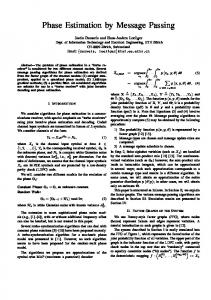
I. I NTRODUCTION Flash memory has become a leading storage media thanks to its many excellent features such as random access and high storage density. However, it also faces significant reliability and endurance challenges. In flash memory, programming cells with lower charge levels to higher levels can be done efficiently, while the opposite requires erasing the whole block containing millions of cells. Block erasure degrades cell quality, and current flash memory can survive only a small number of block erasures. To mitigate the reliability and the endurance issues, this paper studies write-once memory (WOM) codes that combine erasure-free information rewriting and error correction. WOM was first studied by Rivest and Shamir [18]. In the model of WOM, new information is written by only increasing cell levels. Compared to traditional flash, WOM-coded flash achieves higher reliability when the same amonut of information is written, or writes more information using the same number of program/erase (P/E) cycles. We illustrate these benefits using Fig. 1, where we show the bit error rates (BERs) of the first write and the next rewrite measured for the scheme of this paper in a 16nm flash chip. When using the standard setting for error correcting codes (ECCs), flash memory can survive 14000 P/E cycles without an ECC decoding failure. Using a code constructed in this paper that allows user to write 35% more information, we only need 10370 P/E cycles to write the information. Notice that the raw BER at 10370 P/E cycles is much lower than that at 14000 P/E cycles, hence ECC decoding will have much lower failure rate, which leads to higher reliability. On the other hand, if we use WOM until ECC fails at 14000 P/E cycles, the total amount information that is written requires 18900 P/E cycles to write in traditional flash. WOM codes can also be used for scrubbing the memory. In this use, the memory is read periodically, to correct errors
Raw Bit Error Rate
arXiv:1502.00189v1 [cs.IT] 1 Feb 2015
California Institute of Technology, Pasadena, CA 91125 {eengad,whuang,yli,bruck}@caltech.edu 10
-2
10
-3
10
-4
10
-5
First Write Second Write
0
2000
4000
6000
8000 10000 12000 14000 16000 18000
Program/Erase Cycle Fig. 1.
The raw BERs when using the proposed rewriting scheme.
that were introduced over time. The errors are corrected using an ECC, and the corrected data is written back using a WOM code (see [13]). Many WOM constructions were proposed recently. Codes with higher rates were discovered [12][20], and codes that achieve capacity have also been found [1]. In this paper, we propose an alternative construction of WOM codes. Our scheme differs from the WOM codes mentioned above mainly in two aspects. First, we focus on a specific rewriting model with two writes, where only the second write uses WOM codes. Such rewriting scheme has no code rate loss in the first write, and recent experimental study has demonstrated its effectiveness on improving the performance of solid state drives [22]. Note that, the model of this rewriting scheme is not only an instance of the general WOM model [8], but also an instance of the model studied by Gelfand and Pinsker [5]. Second, our construction is based on binary erasure quantization with low-density-generator-matrix (LDGM) codes. The encoding is performed by iterative quantization studied by Martinian and Yedidia [15], which is a messagepassing algorithm similar to the decoding of low-densityparity-check (LDPC) codes. As LDPC codes have been widely adopted by commercial flash memory controllers, the hardware architectures of message-passing algorithms have been well understood and highly optimized in practice. Therefore, our codes are implementation-friendly for practitioners. Extensive simulations show that the rewriting performance of our scheme compares favorably with that of the capacity-achieving polar WOM code [1] in the rate region where a low rewriting failure rate is desired. For instance, we show that our code allows user to write 40% more information by rewriting with very high success probability. We note that the iterative quantization algorithm of [15] was used in [2] in a different way for the problem of information embedding, which share some similarity with our model. Moreover, our code construction is extended with error correction. The need for error correction is observed in our experiments. As shown in Fig. 1, the BERs of both writes
increase rapidly with the number of block erasures. Constructions of error-correcting WOM codes have been studied in recent literature. Error-correcting WOM codes have been proposed in [3][4][11][21][23]. Different from the existing constructions above, we use conjugate code pairs studied in the context of quantum error correction [7]. As an example, we construct LDGM WOM codes whose codewords also belong to BCH codes. Therefore, our codes allows to use any decoding algorithm of BCH codes. The latter have been implemented in most commercial flash memory controllers. We also present two additional approaches to add error correction, and compare their performance. II. R EWRITING
AND
E RASURE Q UANTIZATION
A. Rewriting Model We consider a model that allows two writes on a block of n cells. A cell has a binary state chosen from {0, 1}, with the rewriting constraint that state 1 can be written to state 0, but not vice versa. All cells are initially set to be in state 1, and so there is no writing constraint for the first write. A vector is denoted by a bold symbol, such as s = (s1 , s2 , . . . , sn ). The state of the n cells after the first write is denoted by the vector s. We focus only on the second write, and we assume that after the first write, the state of the cells is i.i.d., where for each i, Pr{si = 1} = β. We note that the special case of β = 1/2 is of practical importance, since it approximates the state after a normal page programming in flash memory1. The second write is concerned with how to store a message m ∈ F2k by changing s to a new state x such that 1) the rewriting constraint is satisfied, and 2) x represents m. This is achieved by the encoding operation of a rewriting code, defined formally in the following. Definition 1. A rewriting code CR is a collection of disjoint subsets of F2n . Each element of CR corresponds to a different message. Consider M ∈ CR that corresponds to a message m, then for all x ∈ M, we say that x is labeled by m. The decoding function maps the set of labeled vectors into their labels, which are also the messages. To encode a message m given a state s, the encoder needs to find a vector x with label m that can be written over s. If the encoder does not find such vector x, it declares a failure. The rewriting rate of CR is defined by RWOM = k/n. The rewriting capacity, which characterizes the maximum amount of information that can be stored per cell in the second write, is known to be β bits [8]. We are interested in rewriting codes with rates close to the capacity, together with efficient encoding algorithms with low failure probability. The main observation in the design of the proposed rewriting scheme of this paper is that the rewriting problem is related to the problem of binary erasure quantization (BEQ), introduced in the next subsection. 1 In flash memory, the message to be written can be assumed to be random due to data compression and data randomization used in memory controllers.
B. Binary Erasure Quantization The BEQ problem is concerned with the quantization of a binary source sequence s′ , for which some bits are erased. Formally, s′ ∈ {0, 1, ∗}n , where ∗ represents erasures. s′ needs to be quantized (compressed) such that every non-erased symbol of s′ will maintain its value in the reconstructed vector. A reconstructed vector with such property is said to have no distortion from s′ . In this paper we use linear BEQ codes, defined as follows: Definition 2. A linear BEQ code CQ is a subspace of F2n . Each c ∈ CQ is called a codeword of CQ . The dimension of CQ is denoted by r. Each codeword of CQ is labeled by a different r-bits sequence u. Given a BEQ code CQ and a source sequence s′ , a quantization algorithm Q is invoked to find a label u whose codeword c ∈ CQ has no distortion from s′ . If such label is found, it is denoted by u = Q(s′ ), and is considered as the compressed vector. Otherwise, a quantization failure is declared, and Q(s′ ) = Failure. The reconstruction uses a generator matrix GQ of CQ to obtain the codeword c = uGQ . C. Reduction from Rewriting to Erasure Quantization In this subsection we show that the problem of rewriting can be efficiently reduced to that of BEQ. Let CQ be a linear quantization code, and let H be a parity-check matrix of CQ . Construction 3. A rewriting code CR is constructed as the collection of all cosets of CQ in F2n . A decoding function for CR is defined by a parity check matrix H of CQ , such that a vector x ∈ F2n is decoded into its syndrome
DEC H ( x) = xH T .
(1)
Since the dimension of CQ is r, it has 2n−r cosets. Therefore r the rate of CR is RWOM = n− n , implying that k = n − r. We define some notation before introducing the reduction algorithm. Let ( H −1 ) T be a left inverse for H T , meaning that ( H −1 ) T H T is the k × k identity matrix. Define a function BEC : {0, 1}n × {0, 1}n → {0, 1, ∗}n as: � wi if vi = 0 BEC (w, v)i = , ∀i = 1, ..., n ∗ if vi = 1 BEC (w, v) realizes a binary erasure channel that erases entries in w whose corresponding entries in v equal 1. We are now ready to introduce the encoding algorithm for the rewriting problem. Theorem 4. Algorithm 1 either declares a failure or returns a vector x such that x is rewritable over s and xH T = m. Proof: Suppose failure is not declared and x is returned by Algorithm 1. We first prove that x is rewritable over s. Consider i such that si = 0. Then it follows from the definition of BEC that s′i = zi . Remember that Q(s′ ) returns a label u such that c = uGQ has no-distortion from s′ . Therefore, ci = s′i = zi , and x i = ci + zi = zi + zi = 0 = s′i . So x
Algorithm 1 x = ENC ( GQ , m, s): Encoding for Rewriting 2: 3: 4: 5: 6: 7: 8:
z ← m ( H −1 ) T s′ ← BEC (z, s) u ← Q(s′ ) if u = FAILURE then return FAILURE else return x ← uGQ + z end if
Rewriting Failure Rate
1:
can be written over s. To prove the second statement of the theorem, notice that xH T = (uGQ + z) H T = uGQ H T + m( H −1 ) T H T
= m( H −1 ) T H T = m. III. R EWRITING
WITH
10
M ESSAGE PASSING
In this section we discuss how to choose a quantization code CQ and quantization algorithm Q to obtain a rewriting scheme of good performance. Our approach is to use the iterative quantization scheme of Martinian and Yedidia [15], where CQ is an LDGM code, and Q is a message-passing algorithm. This approach is particularly relevant for flash memories, since the hardware architecture of message-passing algorithms is well understood and highly optimized in flash controllers. The algorithm Q can be implemented by a sequential or parallel scheduling, as described in [15, Section 3.4.2]. For concreteness, we consider the sequential algorithm denoted by ERASURE-QUANTIZE in [15]. Since the performance of ERASURE-QUANTIZE depends on the chosen generator matrix, we abuse notation and denote it by Q( GQ , s′ ). Algorithm Q( GQ , s′ ) is presented in Appendix A, for completeness. Finally, we need to describe how to choose a generator matrix GQ that work well together with Algorithm Q. We show next that a matrix GQ with good rewriting performance can be chosen to be a parity-check matrix that performs well in message-passing decoding of erasure channels. This connection follows from the connection between rewriting and quantization, together with a connection between quantization and erasure decoding, shown in [15]. These connections imply that we can use the rich theory and understanding of the design of parity-check matrices in iterative erasure decoding, to construct good generating matrices for rewriting schemes. To make the statement precise, we consider the standard iterative erasure-decoding algorithm denoted by ERASUREDECODE( H, y) in [15], where H is an LDPC matrix and y is the output of a binary erasure channel. Theorem 5. For all m ∈ F2k and z′ , s ∈ F2n , ENC( GQ , m, s) fails if and only if ERASURE-DECODE( GQ , BEC(z′ , s + 1n )) fails, where 1n is the all-one vector of length n. The proof of Theorem 5 is available in Appendix B. The running time of the encoding algorithm ENC is analyzed formally in the following theorem.
0
10
-1
10
-2
10
-3
10
-4
10
-5
Polar Code n = 8192 Polar Code n = 16384 LDGM Code n = 8000 LDGM Code n = 16000 0.36
0.38
0.4
0.42
0.44
0.46
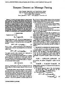
Code Rate Fig. 2.
Rewriting failure rates of polar and LDGM WOM codes.
Theorem 6. The algorithm ENC( GQ , m, s) runs in time O(nd) where n is the length of s and d is the maximum degree of the Tanner graph of GQ . The proof of Theorem 6 is available in Appendix C. Theorems 5 and 6, together with the analysis and design of irregular LDPC codes that achieve the capacity of the binary erasure channel [17], imply the following capacity-achieving results. Corollary 7. There exists a sequence of rewriting codes which can be efficiently encoded by Algorithm 1 and efficiently decoded by Equation (1) that achieves the capacity of the rewriting model β. The proof of Corollary 7 is available in Appendix D. The finite-length performance of our rewriting scheme is evaluated using extensive simulation with the choice of β = 0.5 and GQ to be the parity-check matrix of a Mackay code [14]. The rewriting failure rates of our codes with lengths n = 8000 and 16000 that are relevant to flash applications are compared with those of the polar WOM codes of lengths 213 and 214 [1]. Fig. 2 shows the rewriting failure rates of both codes at different rewriting rate, where each point is calculated from 105 experiments. Remember that the capacity of the model is 0.5. The results suggest that our scheme achieves a decent rewriting rate (e.g. 0.39) with low failure rate (e.g. < 10−4). Moreover, our codes provide significantly lower failure rates than polar WOM codes when the rewriting rate is smaller, because of the good performance in the waterfall region of message-passing algorithm. IV. E RROR -C ORRECTING R EWRITING C ODES The construction of error-correcting rewriting codes is based on a pair of linear codes (C1 , CQ ), that satisfies the condition C1 ⊇ CQ , meaning that each codeword of CQ is also a codeword of C1 . Define C2 to be the dual of CQ , denoted ⊥ . A pair of linear codes ( C , C ), that satisfies by C2 = CQ 1 2 ⊥ C1 ⊇ C2 is called a conjugate code pair, and it is useful in quantum error correction and cryptography [7]. For the flash memory application, we let C1 be an error-correction code, while C2⊥ = CQ is a BEQ code. The main idea in the construction of error-correcting rewriting codes is to label only the codewords of C1 , according to their membership in the cosets of CQ . The construction is defined formally as follows:
( H −1 ) T
HT
Next we define the matrices and to be used in encoding and decoding. Let G1 and GQ be generator matrices of the codes C1 and CQ , respectively, such that each row of GQ is also a row of G1 . Since C1 contains CQ , such matrix pair always exists. Define ( H −1 ) T to be constructed by the rows of G1 that are not rows of GQ . Let H T be a right inverse of ( H −1 ) T . The encoding is performed according to Algorithm 1, with the matrix ( H −1 ) T defined above. Note that in Step 1, z is a codeword of C1 , since each row of ( H −1 ) T is also a row of G1 . In addition, in Step 7, uGQ is also a codeword of C1 (unless Q( GQ , s′ ) fails), since CQ is contained in C1 . Therefore, x = uGQ + z is a codeword of C1 . The decoding can begin by the recovery of x from its noisy version, using the decoder of C1 . The message m can then be recovered by the product xH T . A similar framework was described in [10], which proposed a construction of a repetition code contained in a Hamming code, with a Viterbi encoding algorithm. In this paper we make the connection to the quantum coding literature, which allows us to construct stronger codes. A. Conjugate Codes Construction We look for a conjugate pair (C1 , C2 ) such that C1 is a good error-correcting code, while C2⊥ is a good LDGM quantization code. Theorem 5 implies that C2 needs to be an LDPC code with a good performance over a binary erasure channel (under message passing decoding). Constructions of conjugate code pairs in which C2 is an LDPC code are studied in [6][9][19]. Sarvepalli et al. [19] construct a pair of codes such that C1 is a BCH code and C2 is a Euclidean geometry LDPC code, which is particularly useful for our purpose. This is because BCH codes are used extensively for error correction in flash memories. Below we first briefly review the construction of Euclidean geometry LDPC codes and then discuss the application of the results in [19] to our settings. Denote by EG(m, p s ) the Euclidean finite geometry over F ps consisting of pms points. Note that this geometry is equivalent to the vector space F m p s . A µ-dimensional subspace of or its coset is called a µ-flat. Let J be the number of µ-flats Fm ps that do not contain the origin, and let α1 , ...α psm −1 be the points of EG(m, ps ) excluding the origin. Construct a J × p sm − 1 matrix HEG in the way that its (i, j)-th entry equals 1 if the i-th µ-flat contains α j , and equals 0 otherwise. HEG is the parity check matrix of the (Type-I) Euclidean geometry LDPC code CEG (m, µ, s, p). CEG (m, µ, s, p) is a cyclic code and by analyzing the roots of its generator polynomial, the following result is obtained [19]. ⊥ ( m, µ, s, p ) is contained in a BCH code of Proposition 9 CEG design distance δ = pµs − 1.
Hence we may choose C2 to be CEG (m, µ, s, p) and C1 to be a BCH code with distance equal to or smaller than δ. Some possible code constructions are shown in Table I. Their
TABLE I E RROR - CORRECTING R EWRITING C ODES C ONSTRUCTED FROM PAIRS OF CONJUGATE BCH AND EG-LDPC C ODES .
(m, µ, s, p) (4,1,2,2) (3,1,2,2) (3,1,3,2) (3,1,4,2)
C1 [n, k, δ] [255,247,3] [65,57,3] [511,484,7] [4095,4011,15]
C2 [n, k] [255,21] [65,13] [511,139] [4095,1377]
Rewriting Rate 0.0510 0.1111 0.2192 0.3158
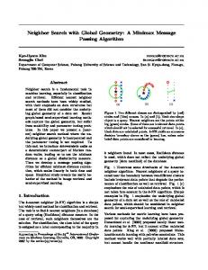
encoding performance, with respect to the probability β that a cell in the state is writable, is shown in Fig. 3. Note from Fig. 3 that a code with smaller rewriting rate achieves a fixed failure rate at a smaller value of β. In particular, the codes corresponding to the top three rows of Table I achieve very small failure rate at β = 0.5, the point of practical interest. These results also show that the slope of the figures becomes sharper when the length of the codes increases, as expected. Out of the three codes that can be rewritten with β = 0.5, CEG (3, 1, 3, 2) poses the best rate and errorcorrection capability. (3, 1, 2, 2) (4, 1, 2, 2)
(3, 1, 3, 2) (3, 1, 4, 2)
1
Rewriting Failure Rate
Construction 8. For c ∈ C1 , let c + CQ be the coset of CQ in C1 that contains c. Then the error-correcting rewriting code is constructed to be the collection of cosets of CQ in C1 .
0.8
0.6
0.4
0.2
0 0
Fig. 3.
0.1
0.2
0.3
β
0.4
0.5
0.6
Encoding performance of the codes in Table I.
V. A LTERNATIVE A PPROACHES FOR E RROR C ORRECTION In this section we present two alternative approaches to combine rewriting codes with error correction. A. Concatenated Codes In this scheme, we concatenate an LDGM rewriting code with a systematic error-correcting code. The outer code is an LDGM rewriting code without error-correction capability, as in Section III. The systematic ECC is used as the inner code. The concatenated scheme is used in the second write. The scheme requires the first write to reserve some bits to store the redundancy of the ECC in the second write. In the second write, the encoder begins by finding a vector x that can be written over the current state. After x is written, the systematic ECC calculates the redundancy bits required to protect x from errors. The redundancy bits are then written into the reserved cells. The decoding of the second write begins by recovering x using the systematic ECC and its redundancy bits. After x is recovered, the decoder of the rewriting code recovers the stored message from x. We note that reserving bits for the second write have a negative effect on the performance of the system, since it
reduces the total amount of information that could be stored in the memory on a given time. Therefore, the next subsection extends the concatenation scheme using a chaining technique, with the aim of reducing the number of bits required to be reserved for the second write. B. Code Chaining The chaining approach is inspired by a similar construction in polar coding [16]. The idea is to chain several code blocks of short length. In the following we use a specific example to demonstrate the idea. We use a BCH code for error correction, since its performance can be easily calculated. We note, however, that LDPC codes may be used in practice, such that the circuit modules may be shared with the rewriting code, to reduce the required area. The performance of LDPC code in the considered parameters is similar to that of BCH codes. A typical BCH code used in flash memory has the parameters [8191, 7671, 81], where the length is 8191, the dimension is 7671, and the minimum distance is 81. If this code is used in a concatenated scheme for the second write, the first write needs to reserve 8191 − 7671 = 520 bits for redundancy. To reduce the amount of required reserved bits, we consider the chaining of 8 systematic BCH codes with the parameters [1023, 863, 33]. The encoding is performed sequentially, beginning with the rewriting encoding that finds a vector x1 of 863 bits. The vector x1 represents a message m1 of 310 bits, according to an [863, 310]-LDGM rewriting code. Once x1 is found, the BCH encoder finds 1023 − 863 = 160 redundancy bits to protect x1 , as in the concatenated scheme. The encoder then “chains” the redundancy bits forward, by encoding them, together with 150 new information bits, into another block of 863 bits, using the [863, 310]-LDGM code. Let m2 denote the vector of 310 bits encoded into the second block. m2 contains the 160 redundancy bits of x1 , together with the additional 150 information bits. Note that once m2 is decoded, the redundancy bit of x1 are available, allowing the recovery x1 , and then m1 . The encoding continues in this fashion 8 times, to write over a total of 8 blocks, each containing 863 cells. The 160 redundant bits used to protect x8 are stored in the reserved cells. The decoding is done in the reverse order, where each decoded vector contains the redundancy bits of the previous block. C. Comparison We compare the different error-correction approaches, and discuss their trade-offs. The first code in the comparison is a conjugate code pair, described in Section IV. We use a conjugation of a [511, 484, 7]-BCH code containing a [511, 372]LDGM code, dual to the (3, 1, 3, 2)-Euclidean geometry LDPC code in Table I. The second code in the comparison is a concatenation of an outer [7671, 2915]-LDGM Mackay rewriting code with an inner [8191, 7671, 81]-BCH code. The third code is a chaining of 8 blocks of [863, 310]-LDGM Mackay codes, each concatenated with a [1023, 863, 33]-BCH code. We compare the decoding BER PD , the fraction α of bits required to be reserved, and the rewriting rate RWOM of the codes. The encoding failure rate of each of the three codes for β = 0.5 is below 10−3 . PD is estimated with a standard
TABLE II E RROR - CORRECTING REWRITING CODES OF LENGTH ≈ 8200.
Code Conjugated Concatenated Chained
PD 10−5 10−16 10−16
α 0% 6.3% 2%
RWOM 0.21 0.35 0.19
flash memory assumption of a raw BER of 1.3 × 10⁻³ . To achieve a comparable code length, the conjugated code is assumed to be used 16 times in parallel, with a total length of 511 × 16 = 8176. The comparison is summarized in Table II. Flash systems require PD below 10−15. We see in Table II that conjugated code still do not satisfy the reliability requirement. We also see that concatenated codes that satisfy the reliability requirement need a large fraction of reserved space. The chained code reduces the fraction of reserved space to 2%, with a rate penalty in the second write. R EFERENCES [1] D. Burshtein and A. Strugatski, “Polar write once memory codes,” IEEE Trans. Inf. Theor., vol. 59, no. 8, pp. 5088–5101, Aug. 2013. [2] V. Chandar, E. Martinian, and G. W. Wornell, “Information embedding codes on graphs with iterative encoding and decoding,” in Proc. ISIT, July 2006, pp. 866–870. [3] E. En Gad et al., “Polar coding for noisy write-once memories,” in Proc. ISIT, June 2014, pp. 1638–1642. [4] A. Gabizon and R. Shaltiel, “Invertible zero-error dispersers and defective memory with stuck-at errors,” in APPROX-RANDOM, 2012, pp. 553–564. [5] S. Gel’fand and M. Pinsker, “Coding for channel with random parameters,” Problems of Control Theory, vol. 9, no. 1, pp. 19–31, 1980. [6] M. Hagiwara and H. Imai, “Quantum quasi-cyclic ldpc codes,” in Proc. ISIT, June 2007, pp. 806–810. [7] M. Hamada, “Conjugate codes for secure and reliable information transmission,” in Proc. ITW, Oct 2006, pp. 149–153. [8] C. Heegard, “On the capacity of permanent memory,” IEEE Trans. Inf. Theor., vol. 31, no. 1, pp. 34–42, January 1985. [9] L. Ioffe and M. Mézard, “Asymmetric quantum error-correcting codes,” Phys. Rev. A, vol. 75, p. 032345, Mar 2007. [10] A. Jacobvitz, R. Calderbank, and D. Sorin, “Writing cosets of a convolutional code to increase the lifetime of flash memory,” in Proc. Allerton, Oct 2012, pp. 308–318. [11] A. Jiang et al., “Joint rewriting and error correction in write-once memories,” in Proc. ISIT, 2013, pp. 1067–1071. [12] A. Jiang, M. Langberg, M. Schwartz, and J. Bruck, “Trajectory codes for flash memory,” IEEE Trans. Inf. Theor., vol. 59, no. 7, pp. 4530–4541, July 2013. [13] Y. Li, A. Jiang, and J. Bruck, “Error correction and partial information rewriting for flash memories,” in Proc. ISIT, June 2014, pp. 2087–2091. [14] D. MacKay, “Good error-correcting codes based on very sparse matrices,” IEEE Trans. Inf. Theor., vol. 45, no. 2, pp. 399–431, Mar 1999. [15] E. Martinian and J. S. Yedidia, “Iterative quantization using codes on graphs,” in Proc. Allerton, 2003. [16] M. Mondelli, S. Hassani, R. Urbanke, and I. Sason, “Achieving Marton’s region for broadcast channels using polar codes,” in Proc. ISIT, June 2014, pp. 306–310. [17] P. Oswald and A. Shokrollahi, “Capacity-achieving sequences for the erasure channel,” IEEE Trans. Inf. Theor., vol. 48, no. 12, pp. 3017– 3028, Dec 2002. [18] R. Rivest and A. Shamir, “How to reuse a write-once memory,” Information and Control, vol. 55, no. 1-3, pp. 1–19, 1982. [19] P. K. Sarvepalli, A. Klappenecker, and M. Rötteler, “Asymmetric quantum codes: constructions, bounds and performance,” Proc. Roy. Soc. of Lond. A Mat., vol. 465, no. 2105, pp. 1645–1672, 2009. [20] E. Yaakobi et al., “Codes for write-once memories,” IEEE Trans. Inf. Theor., vol. 58, no. 9, pp. 5985–5999, September 2012. [21] E. Yaakobi, P. Siegel, A. Vardy, and J. Wolf, “Multiple error-correcting wom-codes,” IEEE Trans. Inf. Theor., vol. 58, no. 4, pp. 2220–2230, April 2012.
[22] G. Yadgar, E. Yaakobi, and A. Schuster, “Write once, get 50% free: Saving ssd erase costs using wom codes,” in USENIX FAST, 2015. [23] G. Zemor and G. D. Cohen, “Error-correcting wom-codes,” IEEE Trans. Inf. Theor., vol. 37, no. 3, pp. 730–734, May 1991.
A PPENDIX A I TERATIVE Q UANTIZATION A LGORITHM We denote GQ = ( g1 , . . . , g n ) such that g j is the j-th column of GQ . Algorithm 2 u = Q( GQ , s′ ). 1: 2: 3: 4: 5: 6: 7: 8: 9: 10: 11: 12: 13: 14: 15:
v ← s′ while ∃ j such that v j 6= ∗ do if ∃i such that ∃!j for which GQ (i, j) = 1 and v j 6= ∗ then Push (i, j) into the Stack. v j ← ∗. else return FAILURE end if end while u ← 0n−k while Stack is not empty do Pop (i, j) from the Stack. ui ← u · g j + s′j end while return u
where s is distributed i.i.d. with Pr{si =} = β. The right-hand side is the decoding-failure probability of an LDPC code with parity-check matrix GQ over a binary erasure channel, using message-passing decoding. The erasure probability of the channel is 1 − β, because Pr{s¯i = 1} = 1 − Pr{si = 1}. The capacity of a binary erasure channel with erasure probability 1 − β is β. This is also the capacity of the rewriting model. In addition, the rate of an LDPC code with parity-check matrix GQ is equal to the rate of a rewriting code constructed by the cosets of CQ . It is shown in [17] how to construct a sequence of irregular LDPC codes that achieves the capacity of the binary erasure channel. Such sequence, used for rewriting codes, achieves the rewriting capacity. A PPENDIX E H ANDLING E NCODING FAILURES The encoding failure event could be dealt with in several ways. A simple solution is to try writing on different invalid pages, if available, or to simply write into a fresh page, as current flash systems do. If the failure rate is small enough, say below 10−3, the time penalty of rewriting failures would be small. For an alternative solution, we state a reformulation of [15, Theorem 3]. Proposition 10. For all m, m′ ∈ F2k and s ∈ F2n , ENC( GQ , m, s) fails if and only if ENC( GQ , m′ , s) fails. Proof: As in Algorithm 1, let z = m( H −1 ) T and = BEC(z, s). Note that ENC( GQ , m, s) fails if and only if Q( GQ , s′ ) fails. By Algorithm 2, the failure of Q( GQ , s′ ) is determined only according to the locations of erasures in s′ , and does not depend on the values of the non-erased entries of s′ . Since s′ = BEC(z, s), the locations of erasures in s′ are only determined by the state s. This completes the proof. s′
A PPENDIX B P ROOF OF T HEOREM 5 Proof: As in Algorithm 1, let z = m( H −1 ) T and s′ = BEC(z, s). Now according to Algorithm 1, ENC( GQ , m, s) fails if and only if Q( GQ , s′ ) fails. According to [15, Theorem 4], Q( GQ , s′ ) fails if and only if ERASURE-DECODE( GQ , BEC(z ′ , s + 1n )) fails. This completes the proof. A PPENDIX C P ROOF OF T HEOREM 6 Proof: We first show that Step 1 of Algorithm 1 runs in time O(n) if ( H −1 ) T is chosen in the following way. For any CQ , its parity check matrix H can be made in to systematic form, i.e., H = ( P I ), by row operations and permutation of columns. Then ( H −1 ) T can be chosen as (0k×n−k Ik ), and so z = m ( H −1 ) T = ( 0 n − k m ) . By [15, Theorem 5], Step 3 of Algorithm 1 runs in time O(nd). By the definition of d, the complexity of Step 7 is also O(nd). Therefore O(nd) dominates the computational cost of the algorithm. A PPENDIX D P ROOF OF C OROLLARY 7 Proof: Let s¯ = s + 1n . Then it follows from Theorem 5 that for all GQ , m ∈ F2k , z′ ∈ F2n , Pr{ ENC ( GQ , m, s) = Failure} = Pr{ERASURE-DECODE ( GQ , BEC(z′ , s¯)) = Failure},
Proposition 10 implies that whether a page is rewritable does not depend on the message to be written. This property suggests that the flash controller can check whether a page is rewritable right after it is being invalidated, without waiting for a message to arrive. An invalid page could be marked as ‘unrewritable’, such that data would be rewritten only into rewritable pages. This policy would guarantee that the rewriting of a new message always succeed. However, this policy also implies that the message passing algorithm would run more than once for the rewriting of a page.