Hindawi Wireless Communications and Mobile Computing Volume 2018, Article ID 5253840, 7 pages https://doi.org/10.1155/2018/5253840
Research Article Robust Drones Formation Control in 5G Wireless Sensor Network Using mmWave Shan Meng ,1 Xiaojian Su ,1 Zhixian Wen Yimin Zhou ,3 and Weiguo Yang4
,1,2 Xin Dai
,1
1
College of Information Engineering, Shenzhen University, Shenzhen, China Shenzhen ACUS Tech. Co. Inc., Shenzhen, China 3 Shenzhen Institutes of Advanced Technology, Chinese Academy of Sciences, Shenzhen, China 4 Shenzhen Konka Telecommunications Technology Co., LTD, Shenzhen, China 2
Correspondence should be addressed to Yimin Zhou;
[email protected] Received 1 December 2017; Accepted 3 April 2018; Published 14 May 2018 Academic Editor: Michel Kadoch Copyright © 2018 Shan Meng et al. This is an open access article distributed under the Creative Commons Attribution License, which permits unrestricted use, distribution, and reproduction in any medium, provided the original work is properly cited. The drones formation control in 5G wireless sensor network is discussed. The base station (BS) is used to receive backhaul position signals from the lead drone in formation and launches the beam to the lead one as the fronthaul flying signal enhancement. It is a promising approach to raise the formation strength of drones during flight control. The BS can transform the direction of the antennas and transmit energy to the lead drone that could widely enlarge the number of the receivers and increase the transmission speed of the data links. The millimeter-Wave (mmWave) communication system offers new opportunities to meet this requirement owing to the tremendous amount of available spectrums. However, the massive non-line-of-sight (NLoS) transmission and the site constraints in urban environment are severely challenging the conventional deploying terrestrial low power nodes (LPNs). Simulation experiments have been performed to verify the availability and effectiveness of mmWave in 5G wireless sensor network.
1. Introduction Wireless Sensor Network (WSN) has been widely applied in numerous fields, such as satellite communication, object detection, human health monitoring, and environmental protection [1]. Although the WSN can be used flexibly, it is rather difficult to build a distributed communication network for large-scale data flows in damaged communication environments. Clustering is an option [2]. With the rapid development of mobile broad-band service in the next generation mobile networks, mmWave (millimeterWave) plays the primary role of updating the network that utilizes the signal frequencies in the range [20–300] GHz [3, 4]. Since mmWaves include abundant spectrums, they are substantially deployed in the next generation mobile heterogeneous networks (HetNets) to improve the coverage capacity in wireless network [5]. The ground-aerial system is usually adopted in WSN forming a promising solution to increase the signal coverage
capacity temporarily in 5G network. Recently, with the development of cutting-edge technology in 5G, 5G New Radio (NR) and the new standard of the OFDM (Orthogonal Frequency Division Multiplexing) air interface would bring lots of changes in our life. The drone base station (drone-BS) can achieve wide range communication without any data transmission links disturbance, especially when adverse weather occurs [6]. Due to the fast deployment of drones, they can also address temporary coverage issues in remote locations, or when grounded wireless deployment is destroyed by natural disasters. Moreover, the bottom small cells are becoming denser to further boost the spectrum efficiency in the next generation of HetNets [7, 8]. It would increase the difficulties of deploying low power nodes (LPNs) due to certain specific constraints from the station deployment, like opposite to the electromagnetic radiation at dense residential communities, cost and space limitation at stadiums, and so on. Furthermore, heavy nonline-of-sight (NLoS) obstruction would cause blockage and
2 hidden terminal problems [9, 10], which is more common in mmWave small cell network due to poor diffraction in the mmWave band. It could seriously compromise the mmWave coverage capacity [5]. Recently, lots of technical companies have put their effort to enlarge the communication volume and enhance the transmission speed via unmanned aerial vehicles (UAVs) [11]. Through such a new system, various demands could be applied [12]. mmWave beam in 5G network can assist ground network of BSs to enlarge the capacity and prevent temporary congestion in confined places such as stadiums. It can also provide additional coverage range in remote areas or when the BSs are out of order due to severe weather conditions, vandalism, transmission problems, and so on. The wide frequency spectrum signal has the ability of data propagation enhancement in unpredicted conditions [13]. The fresh system can also reduce the links cost and improve the efficiency [14]. So new technologies and methods are developed to establish the communication network in order to increase the receivers number and data links coverage capacity. In this paper, we propose a ground-aerial transmission system to address these problems in the conventional terrestrial LPNs deployment for the next generation HetNets. Our aim is to provide a regional capacity enhancement in the traffic hotspots by mmWave in 5G network. It is known that mobile users are dynamically and randomly distributed in the urban area, resulting in temporal events or daily commuting. Traffic hotspots, typically with crowded users, periodically, and their blockage would put heavier demand on the capacity of mobile data access. Instead of permanent capacity improvement by deploying denser terrestrial LPNs, the proposed method could temporarily enhance the original capacity converge of signals in wireless BS system. In this way, it could overcome site-specific constraints, decrease the cost of the equipment installment, and reduce the obstructed transmission problems. Moreover, due to the adoption of mmWave spectrum, the communication interference would be decreased greatly. The remainder of the paper is organized as follows. Section 2 describes the involved signal transmission models. Section 3 describes the proposed algorithm and the simulation experiments performed to demonstrate the efficiency of the system. Conclusion and future work are given in Section 4.
2. The System Model In this section, the involved signal transmission models in the communication network are discussed. 2.1. The Signals Transmission Model and the Receiver Distribution 2.1.1. Path-Loss Model. The path-loss model is used to describe the signal power distribution during the transmission. Only a few air-to-ground path-loss models can be found in the literature. Here the path-loss model presented in [15] is adopted, where the effectiveness of the received power can
Wireless Communications and Mobile Computing be increased greatly, that is, signal diffraction. The line-ofsight (LoS) connection probability between a transmitter and a receiver is an important input factor in channel modeling and it can be formulated as [15, 16] 𝑃 (LoS) =
1 1 + 𝑎 exp (−𝑏 ((180/𝜋) 𝜃 − 𝑎))
(1)
𝑃 (LoS) = 1 − 𝑃 (𝑁LoS) where 𝑃(⋅) is the connection probability function; 𝑎 and 𝑏 represent different environmental areas such as city and countryside; 𝜃 is the elevation angle equal to arctan (ℎ/𝑟), where ℎ is the altitude of the new system and 𝑟 represents horizontal distance between the lead drone and the BS. Assuming shadow interference is ignored and the average path-loss can be described in a probabilistic manner [3], PL (dB) = 20 log (
4𝜋𝑓𝑐 𝑑 ) + 𝑃 (LoS) 𝜂LoS 𝑐
(2)
+ 𝑃 (NLoS) 𝜂𝑁LoS , where the first term on the right side of (2) is the free space path-loss (FSPL) according to the Friis equation; 𝑓𝑐 represents the frequency of the baseband signal; 𝑐 stands for the light speed and 𝑑 is the distance between a receiver and the BS, equal to √ℎ2 + 𝑟2 . 𝜂LoS and 𝜂𝑁LoS delegate the loss of the two primary connections, and their values are dependent on the respective environment. 2.1.2. Spatial Receivers Distribution. To obtain heterogeneity in the spatial receiver distribution, we utilize a Matern cluster process [9, 17]. It is a double Poisson cluster process, where the parent points are the center of the clusters created by a homogeneous Poisson process. The daughter points, representing receivers in the model, are uniformly scattered in circles with radius V around the parent points by using another homogeneous spatial Poisson process. Thus the density function, 𝑓(𝑧) of a given user in the location is described as 1 { 2 𝑓 (𝑧) = { 𝜋V {0
if ‖𝑧‖ ≤ V
(3)
otherwise.
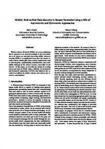
2.2. The Channel Model 2.2.1. The Ray Tracing Model. The ray tracing propagation can be formulated in several models assuming that there are several point sources in the space, named direct rays, reflected and transmitted rays, diffracted rays, and scattered rays. Direct rays model is the simplest model to discuss the scene where the rays start from the source point to the target point directly, satisfying the LoS transformation. Reflected and transmitted rays models could be used to describe that the rays start from the source point but reflecting one or more than one times to the target point while transmitting in different mediums. Diffracted rays model is more complicated compared with models stated above, for the rays from
Wireless Communications and Mobile Computing
3
source point direct rays
source point
source point scattered rays diffracted rays
reflect rays
source point
Figure 1: Four ray tracing models: A direct rays; B reflected and transmitted rays; C diffracted rays; and D scattered rays.
source point would generate numerous diffracted rays from diverse angles after passing different mediums, which would increase the calculation difficulty of the rays at the target point. Scattered rays model is a special model defined in the rough surfaces that could be assumed as the random rays used by object effect incorporation. Besides, the ray tracing model also can be employed in the complicated communication environments, such as the crowded market. The mentioned ray tracing models are shown in Figure 1. Let us consider a MIMO (multiinput multioutput) system that the 𝑘th single-antenna UE (user equipment) transmits signals with 𝑁 antennas simultaneously. Assuming the NLoS channel is used, the channel model can be generalized by 𝐺 = 𝐻𝐷1/2 ,
(4)
where 𝐷 = diag{𝛽1 , . . . , 𝛽𝑘 , . . . , 𝛽𝑚 } represents the massive transmission and 𝛽𝑘 = 𝜙𝑑𝑘−𝛼 𝜉𝑘 (𝑘 = 1, 2, . . . , 𝑚) is a constant value delegating positive relationship between the carried frequency and the frequency carrying the signal. 𝑑𝑘 is the distance between the evolved Node Base station (eNB) and the 𝑘th UE, 𝛼 is the path-loss coefficient, and 𝜉𝑘 is the log2 normal shadow fading coefficient with 10log10 𝜉𝑘 ∼ 𝑁(0, 𝜎sh ); 𝑁×𝐾 𝐻∈𝜗 is the fast fading matrix. 2.2.2. i.i.d. Rayleigh Channel Model. 𝐻 = [ℎ1 , ℎ2 , . . . , ℎ𝑘 ] are the i.i.d. (independent identical distribution) variables that obey Gaussian random rule; ℎ𝑛,𝑘 ∼ 𝜗𝑁(0, 1) (𝑛 = 1, 2, . . . , 𝑁; 𝑘 = 1, 2, . . . , 𝐾). The favorable propagation i.i.d. Rayleigh channel running in large-scale MIMO system is followed by 1 𝐻 𝐺 𝐺 ≈ 𝐷, 𝑁
𝑁 ≥ 𝐾.
(5)
According to the large number of laws, we can find that one characteristic of the favorable propagation is the orthogonality of the different UE channels: {0 1 𝐻 ℎ𝑖 ℎ𝑗 ≈ { 𝑁 1 {
𝑖 ≠ 𝑗 𝑖 = 𝑗.
(6)
Another is the channel harden phenomenon; namely, the Euclidean norm of each UE channel approximates to the large-scale fading factor [18]: 1 2 𝑔 ≈ 𝛽𝑘 , 𝑘 = 1, 2, . . . , 𝐾. 𝑁 𝑘
(7)
2.2.3. The Correlation Channel Model. The fast fading channel elements can be formulated using the correlated matrix and the Gaussian vector: ℎ𝑘 = 𝑅𝑘 V𝑘
𝑘 = 1, 2, . . . , 𝐾,
(8)
where the steering matrix 𝑅𝑘 ∈ 𝜗𝑁×𝐷𝑘 contains 𝐷𝑘 steering vectors and V𝑘 ∼ 𝜗𝑁(0, 𝐼𝐷𝑘 ) when the linear antenna array is assumed, and the steering matrix 𝑅𝑘 can be written as 𝑅𝑘 =
1 [𝑎 (𝜃𝑘,1 ) , 𝑎 (𝜃𝑘,2 ) , . . . , 𝑎 (𝜃𝑘,𝐷𝑘 )] , 𝐷𝑘
(9)
where 𝜃𝑘,𝑖 is the 𝑖th horizontal angles of arrival of 𝑘th UE and the steering vector 𝑎(𝜃𝑘,𝑖 ) ∈ 𝜗𝑁×1 is given as 𝑎 (𝜃𝑘,𝑖 ) = [1, 𝑒(𝑗2𝜋𝑑/𝜆)sin𝜃𝑘,𝑗 , . . . , 𝑒(𝑗2𝜋(𝑁−1)𝑑/𝜆)sin𝜃𝑘,𝑗 ] ,
(10)
where 𝑑 is the distance from the neighbor antennas in the system and 𝜆 is the carrier wavelength.
4
Wireless Communications and Mobile Computing Z
Z
G
G
Y
r
dz
Y
X dz X
dy
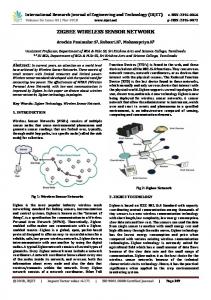
Figure 2: The traditional antenna matrix in a rectangle shape of the BS.
d
2r N
Figure 3: The barrel shape of the antenna.
Generally, the steering vector in the traditional antenna shape can be obtained: 𝑎 (𝜃𝑘,𝑖 , 𝜙𝑘,𝑖 ) = vec {[1, 𝑒(𝑗2𝜋𝑑/𝜆)sin𝜃𝑘,𝑗 , . . . , 𝑒(𝑗2𝜋(𝑁−1)𝑑/𝜆)sin𝜃𝑘,𝑗 ]
𝑇
(11)
⊗ [1, 𝑒(𝑗2𝜋𝑑/𝜆)sin𝜙𝑘,𝑗 , . . . , 𝑒(𝑗2𝜋(𝑁−1)𝑑/𝜆)sin𝜙𝑘,𝑗 ]} , where 𝜙𝑘,𝑗 represents the elevation angle of the arrival. ⊗ delegates the Creinner product and vec{⋅} denotes the vectorization of the matrix.
3. The Method of Signal Transmission for Drones Formation Control 3.1. The Proposed Method. To prove the proposed method is useful in heavy load cases to enhance the received power, we set this section to illustrate completely. According to the system stated above, we first provide the traditional shape of the antenna, described in Figure 2. As shown in Figure 2, we use Cartesian coordinate system to describe the original shape; 𝑑𝑦 is the distance between the neighboring antennas; 𝑑𝑧 is the altitude between the linear antennas layer; 𝜃 and 𝜙 are the horizontal and vertical angles of the receivers and BS; 𝐺 is the beamforming direction. Obviously, the shape can only receive the signals in limited angles; meanwhile, this shape is cumbersome and inconvenient to be deployed on the flying objects that contribute little for transmitting signals from BS among drones formation. In order to overcome the issues, we propose a novel barrel antenna shape to be deployed for the drones formation. The new shape is depicted in Figure 3. First, the ray tracing model and receiver spatial distribution theory are adopted as the system model. It would help to establish the communication environment foundation. Then, the correlation channel model is chosen. As illustrated in Figure 3, the Cartesian coordinate system is also used to describe the fresh shape. 𝑑(2𝜋𝑟/𝑁) is the arc
length of the whole circle that is used to replace the straight distance between the neighbor antennas. 𝜃 and 𝜙 are the horizontal and vertical angles of the arrival object. The single circle antenna array is stacked several times, in order to obtain the final antenna matrix. Through such fresh method, the new shape could powerfully strengthen the robustness of communication links, with a clear antenna shape of barrel based on circle array of antennas. Since all the angles could be covered by using antenna in barrel shape on the drones, it would enhance quality and the received power while communicating to BS effectively and conveniently. Further, deploying such construction of antenna also acts well in receiving fronthaul signal from BS because of its all-round running antennas array. Based on ((8)–(11)), and the general antenna shape, the steering vector can be rewritten as 𝑎 (𝜃𝑘,𝑖 ) = [1, 𝑒(𝑗2𝜋((2𝜋𝑟/𝑁))/𝜆)sin𝜃𝑘,𝑗 , . . . , 𝑒(𝑗2𝜋(𝑁−1)((2𝜋𝑟/𝑁))/𝜆)sin𝜃𝑘,𝑗 ] ,
(12)
where 𝑟 and 𝑁 are the radium and the antenna numbers in the single circular antenna array. Furthermore, the steering matrix can be calculated as 𝑎 (𝜃𝑘,𝑖 , 𝜙𝑘,𝑖 ) = V𝑒𝑐 {[1, 𝑒(𝑗2𝜋((2𝜋𝑟/𝑁))/𝜆)sin𝜃𝑘,𝑗 , . . . , 𝑇
𝑒(𝑗2𝜋(𝑁−1)((2𝜋𝑟/𝑁))/𝜆)sin𝜃𝑘,𝑗 ] ⊗ [1,
(13)
𝑒(𝑗2𝜋((2𝜋𝑟/𝑁))/𝜆)sin𝜙𝑘,𝑗 , . . . , 𝑒(𝑗2𝜋(𝑁−1)((2𝜋𝑟/𝑁))/𝜆)sin𝜙𝑘,𝑗 ]} .
The complete system interactive processing is shown in Figure 4. Four layers for new barrel shape antenna are configured with each circular array containing four antenna units. Based on such assumption, we can respectively define two situations to illustrate the experiments process. Situation A (left side) beamforms to the grounded receivers mostly and situation B (right side) delegates that BS beamforms to the
Wireless Communications and Mobile Computing
5
Drones-coordination disabled The BS allocation
The lead drone
SY N
Regular users
The lead drone
SY N
Side lobe signal
AC K
Main lobe signal
BS merges the status Info
N SY AC K
K AC Fo rm a Inf tion o
al ion n cat matio o L or inf
Main lobe signal
Strong Interaction
Calculate received power and SIR of the lead drone
Regular users
The BS allocation
N SY
K AC Fo rm In atio fo n
Weak formation control
Drones-coordination enabled
Strong formation control
al ion n cat atio o L orm inf Side lobe signal
BS merges the status Info
Weak Interaction
Calculate received power and SIR of the lead drone
Section A
Section B
The BS beamforming system effectiveness evaluation
Figure 4: The interaction process between BS and UAVs.
lead drone. Then, we calculate the horizontal angle 𝜙 and vertical angle 𝜃 in Situation A and Situation B, in order to calculate the received power and make the comparison for the two situations. During the signals exchange between BSs and the lead drone, the received power and the signal to interference ratio (SIR) are used as the evaluation indexes of the system, to detect whether there are drones flying through the region. Once the received signal power from BS to the lead drone exceeds that from the original scenario without flying objects, it is identified that the mmWave system can realize the airground signal transmission with satisfied performance. 3.2. Simulation Experiments. The whole simulated scenarios are shown in Figure 5, where the drones fly passing through the trade center region, to illustrate the complete experimental process. Firstly, in Situation A, the BS establishes the communication network with the lead drone and regular users and beamforms to the regular users, transferring the energy of mmWave from BS to receivers, with the weak strength of signal to control the drones flight control. Then, in Situation B, the BS beamforms carrying the strong control signal are sent to the lead drone as the fronthaul signal, compared to Situation A. Finally, we calculate the lead drone’s received power and SIR in such two experimental environments to evaluate the effectiveness of the BS beamforming system.
The Trade Center Region
BS
Figure 5: Drones formation control from the BS.
The parameters used in the experiments of the drones formation flight control are listed in Table 1. Matlab is used as a simulation tool to perform the experiments. It is assumed that there are totally seven Micro BSs with three cells in the area covered 600 × 700 square meters including fifty user equipment in the special cell randomly, described in Figure 6.
6
Wireless Communications and Mobile Computing 1
Table 1: The system parameters.
250 200 150 100 50 0
0.9 0.8 0.7 CDF
0.6 0.5 0.4 0.3 0.2 0.1 0 −130 −120 −110 −100 −90 −80 −70 received power (dBm)
−60
−50
−40
received power (Situation A) received power (Situation B) 3
2
Figure 7: Received power comparison between Situation A and Situation B. 4
−50 −100 −150
0
1
1 0.9
5
−200 −250
0.8
6
0.7 0.6 0 100 −300 −200 −100 distance (m)
200
300
Figure 6: The initialization of the communication environment with the BSs and the drones.
CDF
distance (m)
Parameters Value BS number 6 Cells of each BS 3 Grounded receivers number 1050 Experimental interactions 1000 The horizontal angle for novel antenna −180–+180 The vertical angle for novel antenna 0–+180 SIR in Situation A −25.4148–42.0513 SIR in Situation B 0.8748–62.0443 The received power in Situation A −130.8963–−98.6954 dBm The received power in Situation B −96.1349–17.0412 dBm
0.5 0.4 0.3 0.2
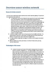
The received power and SIR curves drawn by Cumulative Distribution Function (CDF) in two situations are illustrated in Figures 7 and 8. From the simulation results, it can be seen that the received power in Situation B is higher than that in Situation A. The SIR value in Situation B is also higher than that in Situation A. Therefore, it proves that the drones can receive the signals sent by the BS to keep the formation in control during the swarm flight.
0.1 0 −40
−20
0
20
40
60
80
SIR SIR (Situation A) SIR (Situation B)
Figure 8: The SIRs in Situation A and B.
4. Conclusion
Conflicts of Interest
In this paper, a 5G wireless communication system within BS, user equipment, and UAVs is developed. The drones can fly around the regions where the lead drone sends its position signals to BS as the backhaul and receives the fronthaul signal called mmWave from BS simultaneously. Different from the communication links between the UE and the BS, the launching direction to the lead drone can be set specifically via the antenna with appropriate horizontal and vertical angle. In summary, the simulated system could rise the antenna gain to the lead drone, achieving satisfied performance for UAV formation control. In the future, more different complicated channel models will be considered in diversified communication system.
The authors declare that there are no conflicts of interest regarding the publication of this paper.
Acknowledgments This work was supported under the National Natural Science Foundation of China no. U1713209, Shenzhen Fundamental Research Program no. JCYJ20150629152510439, the National High Technology Research and Development Program 863 no. 2015AA042303, Public Welfare Research and Capacity Building Project of Guangdong Province no. 2015A30401016 and Science and Technology Planning Project of Guangdong Province no. 2017B010117009, and Shenzhen Science
Wireless Communications and Mobile Computing and Technology Innovation Commission Project Grants no. JCYJ20160510154736343 and no. JCYJ20170818153635759.
References [1] I. F. Akyildiz, W. Su, Y. Sankarasubramaniam, and E. Cayirci, “Wireless sensor networks: a survey,” Computer Networks, vol. 38, no. 4, pp. 393–422, 2002. [2] “MiXim Framework Simulation Tool,” http://mixim.sourceforge .net/. [3] M. Agiwal, A. Roy, and N. Saxena, “Next generation 5G wireless networks: A comprehensive survey,” IEEE Communications Surveys & Tutorials, vol. 18, no. 3, pp. 1617–1655, 2016. [4] Y. Niu, Y. Li, D. Jin, L. Su, and A. V. Vasilakos, “A survey of millimeter wave communications (mmWave) for 5G: opportunities and challenges,” Wireless Networks, vol. 21, no. 8, pp. 2657–2676, 2015. [5] M. R. Akdeniz, Y. Liu, M. K. Samimi et al., “Millimeter wave channel modeling and cellular capacity evaluation,” IEEE Journal on Selected Areas in Communications, vol. 32, no. 6, pp. 1164–1179, 2014. [6] E. Kalantari, H. Yanikomeroglu, and A. Yongacoglu, “On the number and 3D placement of drone base stations in wireless cellular networks,” in Proceedings of the 84th IEEE Vehicular Technology Conference, (VTC Fall ’16), Canada, September 2016. [7] S. M. Abd El-atty and Z. M. Gharsseldien, “Performance analysis of an advanced heterogeneous mobile network architecture with multiple small cell layers,” Wireless Networks, pp. 1-2, 2016. [8] R. Q. Hu and Y. Qian, “An energy efficient and spectrum efficient wireless heterogeneous network framework for 5G systems,” IEEE Communications Magazine, vol. 52, no. 5, pp. 94– 101, 2014. [9] Y. Azar, G. N. Wong, K. Wang et al., “28 GHz propagation measurements for outdoor cellular communications using steerable beam antennas in New York city,” in Proceedings of the IEEE International Conference on Communications (ICC ’13), pp. 5143–5147, Budapest, Hungary, June 2013. [10] S. Sun and T. S. Rappaport, “Multi-beam antenna combining for 28 GHz cellular link improvement in urban environments,” in Proceedings of the 2013 IEEE Global Communications Conference, (GLOBECOM ’13), pp. 3754–3759, USA, December 2013. [11] W. Guo, C. Devine, and S. Wang, “Performance analysis of micro unmanned airborne communication relays for cellular networks,” in Proceedings of the 9th International Symposium on Communication Systems, Networks & Digital Signal Processing (CSNDSP ’14), pp. 658–663, IEEE, Manchester, UK, July 2014. [12] A. Merwaday and I. G¨uvenc¸, “UAV assisted heterogeneous networks for public safety communications,” in Proceedings of the IEEE Wireless Communications and Networking Conference Workshops (WCNCW ’15), pp. 329–334, IEEE, New Orleans, La, USA, March 2015. [13] M. Mozaffari, W. Saad, M. Bennis, and M. Debbah, “Unmanned aerial vehicle with underlaid device-to-device communications: Performance and tradeoffs,” in Proceedings of the International Symposium on Communication Systems, Networks & Digital Signal Processing, (CSNDSP ’14), pp. 658–663, 2014. [14] M. Mozaffari, W. Saad, M. Bennis, and M. Debbah, “Drone small cells in the clouds: design, deployment and performance analysis,” in Proceedings of the 58th IEEE Global Communications Conference (GLOBECOM ’15), pp. 1–6, December 2015.
7 [15] R. K. Ganti and M. Haenggi, “Interference and outage in clustered wireless ad hoc networks,” IEEE Wireless Communications Letters, vol. 3, no. 6, pp. 569–572, 2009. [16] A. Al-Hourani, S. Kandeepan, and S. Lardner, “Optimal LAP altitude for maximum coverage,” IEEE Wireless Communications Letters, vol. 3, no. 6, pp. 569–572, 2014. [17] A. Al-Hourani, S. Kandeepan, and A. Jamalipour, “Modeling air-togroundpath loss for low altitude platforms in urban environments,” IEEE Wireless Communications Letters, vol. 3, no. 6, pp. 569–572, 2014. [18] F. Rusek, D. Persson, B. K. Lau et al., “Scaling up MIMO: opportunities and challenges with very large arrays,” IEEE Signal Processing Magazine, vol. 30, no. 1, pp. 40–60, 2013.
International Journal of
Advances in
Rotating Machinery
Engineering Journal of
Hindawi www.hindawi.com
Volume 2018
The Scientific World Journal Hindawi Publishing Corporation http://www.hindawi.com www.hindawi.com
Volume 2018 2013
Multimedia
Journal of
Sensors Hindawi www.hindawi.com
Volume 2018
Hindawi www.hindawi.com
Volume 2018
Hindawi www.hindawi.com
Volume 2018
Journal of
Control Science and Engineering
Advances in
Civil Engineering Hindawi www.hindawi.com
Hindawi www.hindawi.com
Volume 2018
Volume 2018
Submit your manuscripts at www.hindawi.com Journal of
Journal of
Electrical and Computer Engineering
Robotics Hindawi www.hindawi.com
Hindawi www.hindawi.com
Volume 2018
Volume 2018
VLSI Design Advances in OptoElectronics International Journal of
Navigation and Observation Hindawi www.hindawi.com
Volume 2018
Hindawi www.hindawi.com
Hindawi www.hindawi.com
Chemical Engineering Hindawi www.hindawi.com
Volume 2018
Volume 2018
Active and Passive Electronic Components
Antennas and Propagation Hindawi www.hindawi.com
Aerospace Engineering
Hindawi www.hindawi.com
Volume 2018
Hindawi www.hindawi.com
Volume 2018
Volume 2018
International Journal of
International Journal of
International Journal of
Modelling & Simulation in Engineering
Volume 2018
Hindawi www.hindawi.com
Volume 2018
Shock and Vibration Hindawi www.hindawi.com
Volume 2018
Advances in
Acoustics and Vibration Hindawi www.hindawi.com
Volume 2018