(awards CCR-0312079 and CCR-0204278), the SRC and DARPA, is gratefully ... SIAM J. Numer: Anal, 18, 1981. [2] K. Kundert, J. White, ... [6] C. William Gear. Numerical ... ICCAD, 2002. [9] K. E. Brennan, S. L. Campbell, and L. R. Petzold.
50.2
Robust, Stable Time-Domain Methods for Solving MPDEs of Fast/Slow Systems Todd S. Coffey, Scott A. Hutchinson, David M. Day
Ting Mei, Jaijeet Roychowdhury ECE Department University of Minnesota Minneapolis, MN, USA
Sandia National Laboratories Albuquerque, NM, USA
meiting,jr � @ece.umn.edu
tscoffe,sahutch,dmday � @sandia.gov
ABSTRACT
cuits [2]. Later, so-called Fourier-envelope methods were proposed (e.g., [3, 14, 4]), which combined harmonic balance (HB) with time-domain integration methods. This was followed by the advent of the multitime partial differential equation (MPDE) formulation [15, 5], which reformulated the circuit’s DAEs as partial differential equations in separate artificial time scales. The MPDE formulation unified prior time-domain and frequency-domain steady-state and envelope methods, in addition to leading to novel, purely timedomain, solution methods for computing envelopes as well as multitone steady states. One of the advantages of the MPDE formulation is that it provides a framework in which the numerical properties of a variety of envelope and multitone steady state methods can be clearly understood and contrasted. For example, the causes of instability in Fourier envelope methods were determined using the MPDE-based analysis in [8], and workarounds proposed. So far, however, the numerical stability properties of purely time-domain methods for solving the MPDE, important for highly nonlinear circuits, do not appear to have been systematically investigated. In this context, we note that stability results have long been known for ODEs and DAEs (e.g., [6, 7]) and have been instrumental in the development of robust numerical time-integration methods. It is this gap that we address in this paper: we provide a systematic analysis of the numerical stability properties of purely timedomain techniques for solving the MPDE. The motivation for doing so is to clarify which time-domain discretization methods are useful for practical MPDE solution algorithms, and which are not. As with Fourier envelope techniques [8], some purely time-domain MPDE solution methods have been observed empirically to suffer from numerical instability. Understanding the causes is crucial to the wide applicability of time-domain MPDE methods, useful for solving strongly nonlinear circuits, since Fourier approaches cannot efficiently represent strong nonlinearities. During numerical solution of time-domain MPDEs, one is free to choose different discretization methods for each artificial-time dimension. Not surprisingly, this choice can greatly impact the stability of the solution, due to coupling between artificial time dimensions. We first identify concrete combinations of discretization methods that lead to instability. We then explore the underlying cause of the problem by looking into the eigenstructure of the discretized system. We find that applying time-domain discretization methods introduces fast frequency components in the eigenvalues of the discretized system. This results in a change of stability properties from that of the original DAE, explaining the instability of certain combinations of discretizations. We develop our analysis in two hierarchical steps: first, the stability impact of discretizing the fast time scale, and then, the effect of further discretizing the slow time scale. We demonstrate that strange behaviors can be avoided by careful choice of step size along the slow time scale and of combinations of discretization methods for different time scales. As a result of our analysis, we are able to devise robust timedomain MPDE methods that work in a predictable and stable manner. We confirm our results with numerical simulations on a downconversion mixer and a fully differential opamp. We succeed in
In this paper, we explore in detail the stability properties of timedomain numerical methods for multi-time partial differential equations (MPDEs). We demonstrate that simple techniques for numerical discretization can lead easily to instability. By investigating the underlying eigenstructure of several discretization techniques along different artificial time scales, we show that not all combinations of techniques are stable. We identify choices of discretization method and of step size along slow time scales that lead to robust, stable time-domain integration methods for the MPDE. One of our results is that applying overstable methods along one time-scale can compensate for unstable discretization along others. Our novel integration schemes bring robustness to time-domain MPDE solution methods, as we demonstrate with examples. Categories and Subject Descriptors: B.7.2 [Integrated Circuits]: Design Aids – simulation General Terms: Algorithms, Theory, Verification Keywords: MPDE, stability, eigenstructure, time-domain discretization, envelope
1.
INTRODUCTION
In many mixed-signal circuits, internal signals can contain fast and slow components that vary at widely disparate rates. Examples of such circuits include mixers, phase-locked loops, VCOs, automatic gain-control circuits, microwave amplifiers, etc.. In such applications, it is often important to find the slow envelope that rides on fast-varying signal components. Simulation using conventional time integration of the circuit’s Differential Algebraic Equations (DAEs) is usually computationally expensive, since the time steps chosen must be small enough to accurately track the fastest-varying component(s) of the solution. This results in large numbers of time steps being needed to resolve the desired slow envelopes, hence leads to very long computation times. As many simulations are typically carried out during a system’s design flow, the computational problem is further compounded. Researchers have therefore endeavoured to develop faster numerical methods to apply to such problems, with a number of techniques having been developed to solve for slow envelopes. Petzold [1] was apparently first to propose a time-domain envelopefollowing technique for systems of differential equations. Extensions were used for the simulation of switching power and filter cir-
Permission to make digital or hard copies of all or part of this work for personal or classroom use is granted without fee provided that copies are not made or distributed for profit or commercial advantage and that copies bear this notice and the full citation on the first page. To copy otherwise, to republish, to post on servers or to redistribute to lists, requires prior specific permission and/or a fee. DAC 2004, June 7–11, 2004, San Diego, California, USA. Copyright 2004 ACM 1-58113-828-8/04/0006 ...$5.00.
848
finding slow envelope bitstreams robustly, thus reaping the 2-3 orders of magnitude less computation expected of MPDE techniques [5] compared to straightforward time integration of DAEs. The remainder of the paper is organized as follows. In Section 2, we demonstrate stability problems in certain time-domain discretizations of the MPDE. This is followed by Section 3, where several combinations of discretization and integration methods are analysed for stability, leading to predictably stable time-domain MPDE methods. In Section 4, we confirm our analysis with numerical simulations of circuits and demonstrate improvements in computation time.
2.
properties of the system and then establish methods to avoid the instability.
0.5
−0.05 −0.1
−0.15
−0.5 0.01
STABILITY ISSUES FOR TIME-DOMAIN MPDE METHODS
−0.2
0.005 fast time scale(t2) 0
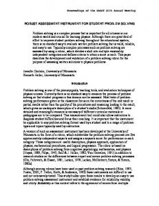
Consider the standard test problem for multi-step integration methods [13]: x˙ � λx � b � t ��� (1) Without loss of generality, we use λ � 10 and b � t ��� sin � 2π100t � here. Physically, this corresponds to a RC network, with time constant τ � 100 ms and an sinusoidal voltage source at 100 Hz, where x � t � is the voltage across the capacitor. Figure 1 shows the transient simulation result of the system. In addition to the fast-varying component resulting from the 100 Hz input, there is also a slow transient envelope caused by the slow RC time constant.
0.4 0.3 0.2 slow time scale(t1)
0.1
0
−0.25
0.5
−0.3 0
0.2 slow time axis (s)
(a) multi-time solution
0.4
(b) slice at t2 � 0
Figure 2: Unstable example: FD and BE are applied in the fast and slow time scales, respectively (h1 � h2 � 1 ms).
3. STABILITY ANALYSIS OF TIME-DOMAIN MPDE METHODS
In time-domain MPDE methods, different discretization methods can be applied to each time scale, but, as we will show, not all combinations are stable. To find the underlying cause of instability, we investigate the eigenstructure of the system after the fast time scale is discretized. We then examine the effect of discretization on the slow time scale. Based on the results from these analysis, robust time-domain MPDEs are established to avoid instability.
0.5 0.4
Capacitor Voltage
0.3 0.2 0.1
3.1 Effect of discretization along the fast time scale on poles/eigenvalues
0 −0.1 −0.2 0
0
0
capacitor voltage (v)
Capacitor Voltage
0.05
0.05
0.1
0.15
0.2 Time
0.25
0.3
0.35
When the backward difference (BD) method is applied along the fast time axis, the ODE corresponding to (2) becomes
0.4
xˆi � t1 �� xˆi � d xˆi � t1 � �� dt1 h2
Figure 1: Transient simulation of the standard test problem.
1 � t1 �
Following [5], the MPDE corresponding to (1) is ∂ ∂ xˆ � t1 t2 � � xˆ � t1 t2 � � λxˆ � sin � 2π100t2 ��� ∂t1 ∂t2
λxˆi � t1 � � b � t2 �
�
i ��� 1 ����� n2 � �
(3)
Here xˆi is the solution along the line t2 ��� i 1 � h2 . The question of stability of xˆi relates to the stability of its homogeneous problem (i.e., with b � t2 � � 0) [9, 10]. Collecting the equations (3) along all t2 ��� i 1 � h2 slices leads to n2 equations and the corresponding homogeneous problem
(2)
In this equation, we choose t1 to be the slow time scale and t2 to be the fast time scale. The time steps along the slow and fast time scales are denoted by h1 and h2 , respectively. To solve the MPDE in the time domain, we first discretize the fast time scale with n2 points, using a finite difference approximation such as forward differences (FD), backward differences (BD) or centered differences (CD). Note that, due to the periodicity of the fast time scale, there does not appear to be a strong reason to choose backward differences over forward differences. This results in the transformation of the MPDE into an ODE (or a DAE in the general case). Then, the differential equation is integrated along the slow time scale using conventional time-integration methods such as backward Euler (BE), trapezoidal or Gear’s methods. The transient solution can then be recovered from the MPDE solution by interpolating along the characteristics, in this case the diagonal line t1 � t2 � t. From Figure 1, the envelope for this system is a slowly-decaying curve. However, with the choice of different discretization methods for different time scales, the MPDE method sometimes fails to find this slow-varying envelope. Figure 2 shows a multi-time solution of this system with FD and BE applied in the fast and slow time scales, respectively, with h1 � h2 � 1 ms. The slow envelope, which is the variation of xˆ � t1 t2 � in t1 (shown in 2(b)), not only contains large oscillations but eventually becomes unbounded for this case. In the remainder of this paper, we first develop a clear understanding of such undesirable phenomena by investigating stability
x˙ � Ax Here, the matrix A � ��
� � �
A�
1 h2 1 h2
λ
where
ℜ n2 � n 2
1 h2
x ��� xˆ1 ����� xˆn2 � T �
is sparse with the structure !"
1 h2
λ ..
(4)
.
1 h2
1 h2
" " "
#
�$��
1 1 P � (5)
λ� I � h2 h2
λ
Here I is the identity matrix and P is a permutation matrix. The identity matrix only shifts the eigenvalues by 1 % h2 λ and the permutation matrix has its eigenvalues around a circle, i.e., e jθ . Therefore, A has n2 distinct eigenvalues (as shown in Figure 3): λˆi ��
1
λ� h2
1 jθ 2π e θ� � i 1� h2 n2 � i ��� 1 ����� n2 � �
(6)
A is diagonalizable and a similarity transformation can transform A into Λ , a diagonal matrix of the eigenvalues of A: M � 1 AM � Λ �
849
(7)
With the change of variables y � M � 1 x, we have a decoupled system of equations y˙ � Λ y �
while it keeps all eigenvalues negative only when h2 is large. In actuality, when the two time scales are widely separated, h2 ) λ1 , so 2 % h2 * λ. In this case, discretization by forward difference leads to an unstable system. An interesting result of this analysis is apparent if one considers the original system (1) for which the solution is always stable. When a FD method is applied to the fast time scale, the intermediate system may become unstable. The reason for this change in the stability is due to the introduction of the term 1 % h2 , which is usuˆ of the new system. ally much bigger than λ, to the eigenvalues (λ) Therefore, the stability is now dominated by this term instead of λ as in the original system (1). Similarly, discretization by BD also has this effect. However, notice that the only difference between these two methods is a sign change of h12 (compare Equations 6 and 9). While all eigenvalues from BD discretization are located on the left of λ, the eigenvalue of the original ODE, they locate on the right of λ for FD case. However, unlike the cases with FD and BD, when CD is applied on the fast time scale, the term h12 does not have any effect on stability because it only appears in imaginary parts of the eigenvalues. Stability in this case is solely determined by the original λ. The same is true for Fourier envelope methods. Notice that eigenvalues are equally spaced for Fourier’s methods while they are sparse at the center but dense at two ends for CD case. We could also consider higher order methods, such as k-th order Gear’s methods(k + 2). Here, we derive the eigenstructure for the case when the second-order Gear’s method is used on the fast time scale. Higher order Gear’s methods have similar eigenstructures. The corresponding DAE is
(8)
ˆ i yi . Thus, the staHere, for each yi , there is a test equation y˙i � λ bility for y, and for x as well, is determined by the eigenvalues and ˆ i ��& 0, for all i � 1 ����� n2 . stability is guaranteed if R e � λ Following the same procedure, we obtain the eigenstructure of the system when discretizing the fast time scale by forward difference, as indicated in Figure 3. 1 1 jθ 2π
λ � i 1� e θ� h2 h2 n2 � i ��� 1 ����� n2 � �
λˆi �
(9)
For the case when centered differences are used, the corresponding matrix A has the structure �� �
� �
A�
λ
1 2h2
1 2h2
λ
1 2h2
1 2h2
..
!"
1 2h2
" " "
.
1 2h2
#
(10)
λ
with n2 eigenvalues 1 2π � i 1� j sin θ θ � h2 n2 � i �(� 1 ����� n2 � �
ˆ i �' λ λ
−λ
−λ
3xˆi � t1 �� 4xˆi � 1 � t1 � � xˆi � d xˆi � t1 � �, dt1 2h2
λxˆi � t1 � � b � t2 ���
h2 small
h2 large 1/h2
(11)
1/h2
The matrix A has the structure: ��
a � b c � �
1/h2
BD
A�
a b
a c
FD
(12)
!"
c
b " c ""
..
#
. b
2 � t1 �
�
aI � bP � cP2
(13)
a
where −λ
Other Methods (Ex: Gear’s methods)
a �' original eigenstructure
CD
2 1 � c �' h2 2h2
It has n2 distinct eigenvalues (as shown in Figure 4):
Fourier
2π � i 1� n2 � i ��� 1 ����� n2 � �
λˆi � a � be jθ � ce j2θ θ �
1/h2 M/T2
−λ
3
λ b � 2h2
−λ
(14)
All eigenvalues are located on the negative half plane. Thus, the resulting system after discretizing the fast time scale by the 2ndorder Gear’s method is a stable one. For the third order method, there may appear positive eigenvalues, depending on the values of both h2 and λ. The trend is that the higher the order of the method, the less stable the resulting system becomes, with positive eigenvalues becoming more likely; in other words, there is a trade-off between accuracy and stability.
Figure 3: Effect of discretization along the fast time scale on poles/eigenvalues. Figure 3 summarizes the transformation of the eigenvalues due to discretization; note that the original ODE system has one negative eigenvalue. For comparison, we have also shown the eigenstructure of Fourier envelope methods [8] for this problem. When BD, CD or Fourier methods are used along the fast time scale, all eigenvalues of the resulting DAE are located on the negative half plane. Therefore, discretization of the fast time scale by these methods results in a stable system. Forward difference, on the other hand, can result in some eigenvalues on the positive half plane when h2 is small
3.2 Effect of discretization on the slow time scale
Continuing the MPDE analysis, the slow time scale is numerically solved utilizing a conventional DAE integration method (e.g., backward Euler or the trapezoidal rule). When the fast time scale is discretized by methods which only generate eigenvalues/poles on the negative half plane (such as BD, CD, Fourier, or 2nd-order Gear), using any A-stable method on the slow time scale results in
850
radius of dashed line 0 OA 01+'0 OA 230 , i.e.,
50 40 30
h1 +
20
Im
10 0
−20 −30 −40 −50
−80
−60
−40
Re
−20
0
20
Figure 4: Locations of poles/eigenvalues after fast time discretization by 2-nd Gear’s method.
Im
2
2nd
1st order
0
stable
O
−1
0 Re
1
2
unstable O (1,0)
A’
B B’
unstable O (1, 0)
To illustrate this point, Table 1 shows the results derived from the above analysis for different h1 values using the test problem (1). Simulation results in Section 4.1 show a perfectly match with the analysis results. For the same h2 , even a small change in h1 may totally change the stability of the solution. For example, if h2 � 1 ms, with h1 � 1 ms, the solution is unstable, while with h1 � 1.1 ms, the solution is stable.
−2
−2
unstable A (1,0)
ˆ and the unstable Figure 6: The relative locations of σ � h1 λ circle of the BE method. The stability region of BE method is the shaded area.
−1
−3 −3
(16)
It is obvious that this equation always holds. Considering these three situations, we conclude that h1 must satisfy (15) to ensure the stability of the solution.
4th 3rd
1
(15) �
h1 1 + h1 �
λ ��� h2 h2
a stable solution. (Recall that a method is said to be A-stable if its stability region includes the entire left half plane.) Some implicit methods, such as backward Euler, the trapezoidal rule and 2ndorder Gear, are A-stable. The 3rd-order Gear’s algorithm, although not A-stable, also could be an option since its stability region almost covers the entire left half plane. Explicit methods, like the forward Euler method, are usually not preferred, since their stability regions only include small area on the left half plane. Explicit Runge-Kutta (RK) methods, which have both higher accuracy and better stability regions than many other explicit methods, are also not good choices for the slow time discretization. The stability regions for ith order RK methods (i � 1 2 3 4) are shown in Figure 5. From the previous section, the ˆ could be as large as +/- h1 % h2 . When imaginary part of σ � h1 λ two time scales are widely separated, we usually choose h1 * h2 . However, from Figure 5, even for the 4th-order RK method, the stability region can not be beyond - 3 along the imaginary coordinate; therefore, it results in unstable solutions. 3
λ
As h1 increases, the center of the dashed circle moves to the right. At some point, h1 � 1 % h2 λ �4� 1 and the two centers overlap. In this situation, the radius of dashed circle h1 % h2 � 1 � h1 λ 5 1 and the solution is always stable. As h1 grows, h1 � 1 % h2 λ �/5 1 and the center of the dashed circle is located to the right of � 1 0 � . ˆ are outside the instability circle, the radius To ensure all σ � h1 λ of dashed line 0 OB 06+'0 OB230 , i.e.,
−λ
−10
2 2 h2
3
h2
h1
1 ms 1 ms 1 ms 1 ms
0.9 ms 1 ms 1.1 ms 10 ms
h1 +
2 h2
No No Yes Yes
2
� λ
stability unstable, blows up quickly unstable, blows up slowly damps slowly damps quickly
Table 1: Calculation results for the test problem using differing h1 values.
Figure 5: Stability regions of Runge-Kutta methods.
Notice here that h1 only needs to be approximately larger than h2 to ensure a stable solution with stability being proportional to the size of h1 . In reality, when two time scales are widely separated, we usually choose h1 * h2 . Therefore, we usually obtain stable solutions without uncovering the potential instability of this combination.
Some implicit methods, such as backward Euler and the 2ndorder Gear’s method, are “overly stable”: they are stable even for ODEs with positive eigenvalues. This suggest a way to get a stable solution even when the system has positive eigenvalues. For instance, with suitable time step sizes along the slow time scale (h1 ), BE can damp out the artificial instabilities introduced by the forward difference discretization of the fast time scale. Early experiments with these methods could easily miss this distinction and reinforce the idea that forward differences are not different from backward differences for MPDE methods. We next look into how to choose h1 in order to obtain a stable ˆ is located at a solution in this case. From (9), we know that σ � h1 λ circle with the center � h1 � 1 % h2 λ � 0 � and the radius h1 % h2 . With fixed h2 , a change in h1 not only moves the center but also changes ˆ the radius. Figure 6 illustrates the relative locations of σ � h1 λ (dashed line) and the unstable circle of the BE method (solid line). ˆ is located to the left of that When h1 is small, the center of σ � h1 λ of the instability circle of the BE method, i.e., h1 � 1 % h2 λ �/. 1. ˆ are located outside the instability circle, the To ensure all σ � h1 λ
3.3 Stable time-domain MPDE methods
To summarize the above analysis, we consider the case of interest ( h22 λ 5 0). We begin with a stable DAE and transform it to a MPDE form. At this point, the equation is still stable prior to applying any discretization. However, when this MPDE form is discretized along the fast time scale, the stability condition of the resulting slow-time DAE changes. With the FD method, the result is an unstable system while with BD, CD or the 2nd-order Gear’s method, the result is a stable system. Then, when numerically integrating the slow time scale, the stability properties change once more. For the former case, only using the “overly” stable methods will result in a stable solution provided that h1 5 h2 (for BE). For the latter case, any A-stable method will result in a stable solution
851
but the explicit methods usually do not work. The results are summarized in table 2 and the discretization flow is shown in Figure 7. Therefore, to ensure the stability of the MPDE solution, one should always use the “Good” combinations in Table 2. Note that if one chooses to use FD and BE (or 2nd-order Gear) along the fast and slow time scales, respectively, the resulting combination will yield a stable overall solution but an unstable form was created after the discretization of the fast time scale. fast
7 slow 7 7
7
FD BD CD 2nd Gear Fourier
FE
BE
Trap
2nd Gear
RK
BAD BAD BAD BAD BAD
ok Good Good Good Good
BAD Good Good Good Good
ok Good Good Good Good
BAD BAD BAD BAD BAD
DAE
stable
89 8:9 8:9 8:9 8:9 8:9 8:9 8:9 8:9 BE :9 :9 :9 :9 :9 :9 :9 :8 DAE 89:9 89 888 :9 888 :9 888 :9 888 FD 888 :9 888 :9 888 :9 888 :8:8:8 :9 :9 89 2nd Gear 9:9 889 8 :9 8 :9 8 :9 8 :9 8 :9 8 :9 8 :9 8 unstable :9 :9 :9 :9 :9 :9 :9 :9 :8 8 8 8 8 8 8 8 8 8 9 : 9 : 9 : 9 : 9 : 9 : 9 : 9 : : 89:9 8 :9 8 :9 8 :9 8 :9 8 :9 8 :9 8 :9 8 :8 MPDE CD stable Fourier A−stable BD DAE 2nd Gear stable Explicit fast time discretization
continuous
capacitor voltage (v)
−0.05
0
−0.1
−0.5
−0.15
−1
−0.2
−1.5
−0.25
−2 0
0.05 slow time axis (s)
0.1
−0.3 0
0.2 slow time axis (s)
(a) h1 = 0.9ms
0.4
(b) h1 = 1 ms
0.05
0 −0.02
0 capacitor voltage (v)
FE
0
0.5
Table 2: Stability summary. Trap
0.05
unstable
−0.04 capacitor voltage (v)
7
x 10
1
capacitor voltage (v)
7
8
1.5
−0.05
−0.1
−0.08 −0.1 −0.12 −0.14
−0.15
stable
−0.06
−0.16
−0.2 0
for h1 > h2 (BE)
stable
0.05
0.1
0.15 0.2 slow time axis (s)
0.25
−0.18 0
0.3
(c) h1 = 1.1ms
unstable
0.1
0.2 slow time axis (s)
0.3
(d) h1 = 10 ms
Figure 8: Test problem: FD and BE along the fast and slow time scale, respectively.
slow time discretization
Figure 7: Discretization flow. 0.02
RESULTS
capacitor voltage (v)
−0.02
capacitor voltage (v)
4.
0
0
We have implemented time-domain MPDE methods using the discretization schemes described above in GnuQAPP and Myce, which are MATLAB-based packages for prototyping and testing analog simulation algorithms. All simulations were performed using MATLAB on an 2.4 GHz, Athlon-XP based PC running Linux (kernel 2.4 series).
−0.04 −0.06 −0.08
−0.1
−0.1 −0.12 0
4.1 Simple linear test problem
0.02
0.04 0.06 slow time axis (s)
0.08
0.1
−0.2 0
0.12
(a) h1 = 0.9ms
Simulation results for the simple linear test problem of Equation 1 are shown in Figures 8 and 9. Here we plot the envelope solution along the t2 � 0 slice. Note that the scales are different. Figure 8 demonstrates how BE along the slow time scale damps out instabilities introduced by the forward difference discretization of the fast time scale. For comparison, we use the same values in Table 1 for the “Good” combinations. In the interest of brevity, we only present results for BD+BE combination. Other “Good” combinations show the same stability properties. Figure 9 indicates that the envelope solution is always stable.
0.05
0.1 0.15 0.2 slow time axis (s)
0.25
0.3
(b) h1 = 10 ms
Figure 9: Test problem: BD and BE along the fast and slow time scale, respectively.
VDD
R
4.2 Simple CMOS down-conversion mixer (4 active transistors)
−VRF
A balanced CMOS direct-downconversion mixer (based on [11]) is shown in Figure 10. The lower pair of MOSFETs generates a current that doubles the LO frequency while the upper pair form a differential pair. This circuit implements a multiplication of the RF and LO signals, with the high-frequency component of the product filtered out by the RC network. In our example, the LO signal is a 450 MHz sinusoid modulated by a 2.5 kHz sinusoid. The RF signal is a 900 MHz carrier modulated by a bit-stream at 10 kbps. The simulation results are illustrated in Figures 11 - 12, using BD and BE in the fast and slow time scales, respectively. As pointed out
−VLO
C
C
R
+VRF
+VLO
Figure 10: Balanced CMOS direct-downconversion mixer.
852
in Table 2, this is always a stable strategy. The figures show both the multi-time solution and a slice through the solution at t2 � 0. Figure 11 show the voltage at one output node. The voltage at the drains of the lower MOSFETs is shown in Figure 12. As can be seen, it doubles the frequency of the LO signal. The envelope, as expected, is a slowly-varying curve. In addition, the slowly changing amplitude of bits illustrates the change of the downconversion gain, which is caused by amplitude changes of LO signal. As this example demonstrates, more than 2 orders of magnitude of speedups can be obtained from robust and stable time-domain MPDE methods compared to traditional time-domain methods. Furthermore, the wider the separation between fast and slow time scales, the greater the obtained speedup. In addition, if the envelopes are the only features of interest, we do not even need to interpolate the multi-time solution, resulting in further speed improvement.
Vout
3
4
2.5
2
2 1.5 Vout
0
−2 6 5 −3
x 10
t2=0 t2=0.5*T2
1 0.5 0
4
30
3
20
2 fast time scale(t2)
10
1 0
0
slow time scale(t1)
(a) multi-time solution
−0.5 −1 −1.5 0
5
10
15 slow time axis
20
25
30
(b) slice at t2 � 0 and t2 � 0 � 5T2
Figure 13: Simulation results: at differential output. 3
3
2.5
vided by this analysis, which has been confirmed by numerical simulations. We have applied our new robust time-domain MPDE techniques to mixed-signal circuits with strong nonlinearities and demonstrated speedups of 2-3 orders of magnitude over traditional transient simulations. We are currently extending stability analysis to the Warped MPDE, useful for analyzing autonomous systems such as voltage-controlled oscillators and phase-locked loops. We expect the adoption of our methods to lead to significant improvements in simulation speed for practical applications with fast/slow signal characteristics.
2.5 2
2
1.5 1.5
1 0.5 3
1
6
2 −9
x 10
4
1
−4
2 0
fast time axis(t2)
0
x 10
0.5 0
2
slow time axis(t1)
(a) multi-time solution
slow time axis
4
6
−4
x 10
(b) slice at t2 � 0
Acknowledgments
Figure 11: Simulation results: at output.
Support of authors Mei and Roychowdhury by Sandia National Laboratories, and additional support of Roychowdhury by the NSF (awards CCR-0312079 and CCR-0204278), the SRC and DARPA, is gratefully acknowledged. Computational resources used include those from the Digital Technology Center and the Supercomputing Institute of the University of Minnesota.
0.45 0.4 0.35
6. REFERENCES
1 0.3
0.5
[1] L. Petzold. An efficient numerical method for highly oscillatory ordinary differential equations. SIAM J. Numer: Anal, 18, 1981. [2] K. Kundert, J. White, and A. Sangiovanni. An envelope-following method for the efficient transient simulation of switching power and filter circuits. In Proc. ICCAD, 1988. [3] E. Ngoya and R. Larchev´eque. Envelop transient analysis: a new method for the transient and steady state analysis of microwave communication circuits and systems. In Proc. IEEE MTT Symp, 1996. [4] P. Feldmann and J. Roychowdhury. Computation of circuit waveform envelopes using an efficient, matrix-decomposed harmonic balance algorithm. In Proc. ICCAD, 1996. [5] J. Roychowdhury. Analyzing circuits with widely separated time scales using numerical PDE methods. IEEE Transactions on Circuits and Systems — I: Fundamental Theory and Applications, 48(5):578–594, 2001. [6] C. William Gear. Numerical initial value problem in ordinary differential equations. PRENTICE-HALL, INC, Englewood Cliff, N.J., 1971. [7] Robert K. Brayton and C. H. Tong. Stability of dynamical systems: A constructive approach. IEEE Transactions on Circuits and Systems, CAS-26:224–234, 1979. [8] J. Roychowdhury. Making Fourier-envelope simulation robust. ICCAD, 2002. [9] K. E. Brennan, S. L. Campbell, and L. R. Petzold. Numerical solution of initial-value problems in differential-algebraic equations, volume 14 of Classics in Applied Mathematics. SIAM, Philadelphia, PA, first edition, 1996. [10] U. M. Ascher and L. R. Petzold. Computer methods for ordinary differential equations and differential-algebraic equations. SIAM, Philadelphia, 1998. [11] Z. Chen, Z. Zhang and J. Lau. A 900mhz cmos balanced harmonic mixer for direct conversion receiver. In Proc. IEEE Radio and Wireless Conference, pages 219–222, 2000. [12] D.A. Johns and K. Martin. Analog integrated circuit design. John Wiley & Sons, INC, 1997. [13] L.O. Chua and P-M Lin. Computer-aided analysis of electronic circuits : algorithms and computational techniques. Prentice-Hall, 1975. [14] D. Sharrit. New Method of Analysis of Communication Systems. MTTS WMFA Nonlinear CAD Workshop, 1996. [15] H-G. Brachtendorf, G. Welsh, R. Laur and A. Bunse-Gerstner. Numerical steady state analysis of electronic circuits driven by multi-tone signals. Electrical Engineering (Springer-Verlag), pages 103–112, 1996.
0.25
0 2.5
6 2 −9
x 10
4
1.5 1 fast time axis(t2)
0
0
slow time axis(t1)
(a) multi-time solution
−4
x 10
2 0.5
0.2 0.15 0.1 0
2
4 slow time axis
6
−4
x 10
(b) slice at t2 � 0
Figure 12: Simulation results:at drains of lower MOSFETs.
4.3 Fully differential op-amp (28 transistors)
We also simulate a fully differential opamp composed of two single-ended output current-mirror opamps [12, page 286]. Here we use the sum of a fast sinusoid and a slow bit stream as the input. The intent of this simulation is to investigate nonlinearities in the amplifier that can cause intermodulations. The simulation results of the differential output are shown in Figure 13. It is obvious that the amplifier saturates: at bit ’1’, the sinusoidal wave becomes flatter than that at bit ’0’. Time-domain MPDE envelope integration on this example runs about 100 times faster than ordinary DAE integration.
5.
CONCLUSIONS
In this paper, we have used eigenstructure analysis to investigate the stability properties of a variety of discretization methods for time-domain MPDE solution. We have proposed robust and stable methods to circumvent instabilities based on the insight pro-
853