2011 International Conference on Multimedia, Signal Processing and Communication Technologies
Rotating Magnetic Field Based Instantaneous Angular Speed Measurement of Low Speed Rotating Machines S. Javed Arif1, Imdadullah2 and M. S. Jamil Asghar3, Member IEEE 1
Department of Electronics Engineering, A.M.U., Aligarh, India Email:
[email protected] 2 Electrical Engineering, University Polytechnic, A.M.U., Aligarh, India Email:
[email protected] 3 Department of Electrical Engineering, A.M.U., Aligarh, India Email:
[email protected] Abstract— For early fault detection and health monitoring of low speed machines the instantaneous angular speed (IAS) measurement with high resolution and accuracy is required. The results show that IAS measurement is much more superior to the conventional methods i.e. analyzing acoustic waveforms, temperature variations, and vibrations etc. However accurate IAS measurement becomes very difficult due to slow and noisy response of the rotary transducers for low speed rotating machines. In the proposed technique, a fast rotating magnetic field (RMF) is used to measure the IAS for low-speed machines. An independent ac source is used to generate a balanced threephase ac voltage, which is applied to the stator windings of a synchro whose rotor is coupled with the rotating member or rotor of a motor. The RMF in the air gap generates emf in the rotor of synchro whose frequency depends upon the slip speed. Since the RMF revolves at a speed, several times the speed of the rotating member or the rotor of motor, hence the IAS measurement becomes very fast and accurate. The proposed scheme is tested successfully for instantaneous change of speed within a range of 0 to 2 rpm. Index Terms—Speed measurements, IAS measurement, tachometers, rotating machines, low speed transducers
I. INTRODUCTION The instantaneous angular speed (IAS) measurement is one of the important issues for applications in the area of fault diagnosis, condition monitoring and control of rotating machines. The word ‘instantaneous’ refers to small duration of time over which the measured speed is reduced to a very small period. In the case of fault detection and overall condition monitoring, the angular speed from a very small fraction of a revolution is obtained to get the required information. Typical applications of IAS measurement include the diagnosis of faults in bearings of diesel engines [1], vibration measurement in electric machines [2],
measurement of noise for machine diagnosis [3] and monitoring the overall conditions of the machines with time [4]. These applications reveal how IAS is useful in fault diagnosis and health monitoring of different types of machines. The IAS measurement is much more useful for low speed machines of cement kilns, paper mills, textile mills and heavy stone crushing machines where the fault diagnosis and condition monitoring is very critical as the abrupt shutdown of these machines would result in serious consequences. A number of methods have been proposed for the measurement of IAS in the literature. However the analog-todigital converter (ADC)-based methods and timer/counterbased methods are commonly used for IAS measurement. The ADC-based methods require longer period of the measurement as the methods are based on averaging processes [5]. In case of a timer/counter based method, the pulses of a pulse-train are counted over a fixed duration of the measurement time. At low speed, this duration is kept large, therefore, a significant delay appears in the response time of the measurement. Moreover, the method results in a loss of one pulse and give significant error during the count of the pulses. [6]. A significant improvement is made in the above method by the constant elapsed time method. However, this method has a serious limitation of “minimum measurable speed,” within a given maximum response time. Therefore, it does not work effectively for a speed below 30 rpm [7]. A sensor-less speed measurement technique is also proposed in the literature for measurement of speed, but the output filters, slows down the response as well as may alter the information output at low angular speed [8]. In general these techniques are not suitable for high resolution and accurate IAS measurement for low speed rotating machines. In the proposed method, a fast RMF is used to generate an emf in the rotor circuit of a synchro [9]. In fact, the rotor of the synchro is mechanically coupled with rotor of the rotating
978 1 4577 1107 7/11/$26.00 ©2011 IEEE
252
2011 International Conference on Multimedia, Signal Processing and Communication Technologies
member. Both the magnitude and frequency of the output voltage depend upon of the speed and difference in the speed. The effect of variation in the magnitude of the output voltage is eliminated by using a zero crossing detector (ZCD) in open-loop mode at the output. Moreover, the RMF is kept faster (several times) than the rotor, therefore, before the completion of even one revolution of the rotor or the rotating member, the RMF rotates several times. Thus a slight deviation in angular speed causes a fast deviation in frequency; hence the IAS measurement becomes extremely fast and accurate. II.
THEORY
The speed (revolution) of a rotating magnetic field in the air-gap of a stator, produced by a balanced three-phase ac supply is given by 120
1
Where P is number of poles and fs is frequency of the stator input voltage or current, in Hz. For a synchro whose rotor is rotating at nr rpm, the relative speed or the slip is (ns – nr), in the direction of ns. However, if it rotates in opposite direction, the slip becomes (ns + nr). The frequency of the induced emf in the rotor circuit is given by 120 120 120
120
2
III.
REALIZATION
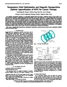
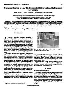
Figure 2 shows the set up for the realization of IAS measurement of low speed rotating machines. To obtain low instantaneous angular speed within a range of 0 to 2 rpm, a three-phase induction motor is used as a prime mover. The speed of this motor is first reduced to a maximum limit of about 10 rpm with the help of adjustable frequency ac drive system. To reduce the speed further, a pulley and wheel arrangement is used, which is mechanically coupled to the rotor of synchro. A sine wave signal of 40 Hz (18 V peak to peak) from a stable arbitrary function generator is supplied to a centretapped transformer. The output of transformer is applied to an RC network (R=100 kΩ and C = 0.1µF), to generate a balanced three-phase, 40 Hz voltages Va1, Vb1, and Vc1 (Fig. 1). These voltages are attenuated to a value of about 100 mv as Va2, Vb2, and Vc2, before feeding into three audio power amplifiers (LM 384N). The outputs of these amplifiers, VA, VB and VC are in turn applied to the stator winding of synchro. Therefore at stationary condition, a sine wave, Vr (40 Hz) is generated at the rotor of the synchro (Fig. 3). IV.
EXPERIMENTAL RESULTS
A. When the rotating member is stationary As long as the rotating member is stationary, the speed of rotor of synchro, S is zero. The frequency fr of Vr of the rotor circuit is equal to fs of Vs of the stator circuit (Fig. 3). The signal Vr is now passed through a ZCD to produce a square waveform, VR with the same frequency (fR = fr), as shown in Fig. 4.
3
Since the supply frequency (fs) and the number of stator poles (P) are constant, therefore, the frequency of the induced emf in the rotor circuit varies linearly with the variation of the rotor speed, nr. For this purpose, a three-phase balanced voltage supply is realized with the help of a sine wave oscillator and a single-phase to three-phase converter using three audio amplifiers as shown in Fig. 1. These voltage signals are applied to the stator winding of a synchro (Fig. 2). When the rotor of the synchro (rotating member) is standstill, the synchro acts as a transformer. Therefore the frequency of rotor emf (fr), is same as that of stator (fr = fs). When the rotor rotates, the frequency is proportional to the slip (ns ∓ nr), Fig. 1. Single-phase to three-phase conversion system
where ns is constant.
253
2011 International Conference on Multimedia, Signal Processing and Communication Technologies
fr = Frequency of induced emf (Vr ) of rotor of synchro. fs = Frequency of induced emf (Vs ) of stator of synchro. fR = Frequency of signal VR at the output of ZCD (fR = fr). TR = Time period of the signal VR at the input of OS. TWR+ = Positive width of the signal VR. TWQ+ = Positive width of signal Q TWG- = Negative width of the pulse at the output of G-1 TWG- = TWR+ - TWQ+ When nr = 0 rpm, TWG- =0 Fig. 2. RMF and synchro based IAS measurement setup
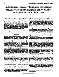
The positive going transition (PGT) of signal, VR with a positive width (TWR+) of 12.5 ms is used to trigger a one shot mono-stable multi-vibrator (OS) as shown in Fig. 5. The components of OS (74LS121N) are chosen to give a signal Q with stable positive pulse width (TWQ+) of 12.5 ms. These two signals are applied to an EX-NOR gate (G-1). The output of G-1 becomes HIGH as the positive width of both the signals, VR and Q is equal as shown in DSO record of Fig. 6 (a). B.
When the rotating member instantaneously changes to different speeds
When the rotating member instantaneously changes to a low angular speed, the RMF revolves in the air gap at a very fast speed of 2400 rpm for a 40 Hz, 2 pole machine (synchro S). Even a very small angular movement of rotor (one tenth of a radian per second) generates an emf, Vr whose frequency, fr in the rotor circuit immediately decreases. The associated time period TR (or 1/fR) and hence the positive width TWR+ of signal, VR at the output of ZCD quickly increases. The PGT of VR triggers OS to produce a signal, Q with stable positive width TWQ+ of 12.5 ms. When the signals VR and Q are applied to G-1, a pulse with negative width is generated at its output on the trailing edge of these signals (VR and Q) as shown in Fig. 5. The width of this pulse depends on the IAS of rotor of synchro, S (or rotating member). The pulse with maximum negative width is proportional to the maximum instantaneous change in angular speed of rotor or rotating member. The calculations for the measurement of IAS with various parameters are given by.
2) When nr instantaneously changes to 1 rpm fs = 40 Hz fr = 40 −
1× 2 120
fR = fr = 39.983 = (1/fR) = 25.010 ms TR TWR+ = TR/2 = 12.505 ms TWQ+ = 12.5 ms TWG- = TWR+ - TWQ+ TWG- = 12.505-12.5 TWG- = 5.210 µs (Theoretical) Figures 6(a)-(b) show the DSO records for IAS measurement within a speed range, 0 to 2 rpm. These results are also tabulated in Table 1.
Fig. 3. Measured three phase voltages, VA, VB, VC at stator winding of synchro (CH#1, CH#2 and Ch#3). Vr (CH#4).
3
120
The output of EX-NOR gate G-1 is HIGH as shown in Fig. 6(a).
TABLE I THEORITICAL AND OBSERVED RESULTS OF THE TEST
12.5
nr rpm (IAS) 0
fR (VR) Hz (Theoretical) 40
fR (VR) Hz (Observed) 39.999
TR=1/ fR ms (Theoretical) 25.00
TWR+ = TR/2 ms (Theoretical) 12.50
TWR+ = TR/2 ms (Observed) 12.50
TWG- (µs) = TWR- TWQ+ (Theoretical) 0
(Observed) 0
12.5
1
39.983
39.983
25.010
12.505
12.50
05.210
6.001
12.5
2
39.966
39.966
25.020
12.510
12.51
10.425
10.08
TWQ+ ms
254
TWG- (µs)
2011 International Conference on Multimedia, Signal Processing and Communication Technologies
Fig. 4. Measured output of rotor, Vr of synchro, S (Ch#1) and output of ZCD, VR (Ch#2) at 40 Hz.
Fig. 6(b) Fig. 6(a)-(b) Measured signal, VR with TWR+ (Ch#1), signal Q with TWQ+ (Ch#2) and output TWG- at G-1 for 0 to 2 rpm respectively (Ch#4).
IAS is measured at the speed of RMF, which is faster than the speed of rotating member. While the RMF completes one revolution in 25 ms but due to the fast measuring mechanism, the deviation in speed is even detected within 12.5 ms. Hence the proposed method provides fast measurement of IAS with high accuracy and resolution. Therefore it is very useful in more accurate and early detection of faults and condition monitoring for the low speed machines.
VI. Fig. 5. Waveforms of signals, VR, Q and output TWG-
[1]
[2]
[3]
[4]
[5] Fig. 6(a) [6]
V.
CONCLUSION
[7]
A novel RMF and synchro based IAS measurement technique has been proposed for low speed machines. The rotor output of synchro is used to measure the IAS of a low speed machine within a range of 0-2 rpm. An adjustable frequency ac drive system with a pulley and wheel arrangement (mechanically coupled to the rotor of synchro) is used to realize the IAS for low speed machines. The instantaneous change in angular speed changes the frequency of induced emf in the rotor circuit of synchrro which is detected in terms of pulses of different pulse-width. As the
[8] [9]
255
REFERENCES
J.G. Yang, L.J. Pu, Z.H. Wang, Y.C. Zhou, X.P. Yan, “Fault detection in a diesel engine by analyzing the instantaneous angular speed,” Mechanical Systems and Signal Processing , vol. 15, no. 3, pp. 549564, 2001. M. Makowski, P. Pietrzak, B. Pokoslawski and A. Napieralski, “Measurement synchronization in the vibration diagnostic system of high power electric machines,” in proc. 2010 MIXDES, 17th International Conf., Lods, Poland, pp. 566 – 569. F. Gu, I. Yesilyurtb, Y. Li, G. Harris, and A. Ball, “An investigation of the effects of measurement noise in the use of instantaneous angular speed for machine diagnosis,” Mechanical Systems and Signal Processing, Elsevier, vol. 20, issue 6, pp. 1444-1460, Aug. 2006. A. Ben Sasi, B.S. Payne, F. Gu, A.D. Ball, “The exploitation of instantaneous angular speed for condition monitoring of electric motors,” in Proc. of 2001 COMADEM, 14th International Conf., Manchester, UK, pp. 311–318. A. Ben Sasi, B. Payne, A. York, F. Gu, A. Ball, “Condition monitoring of electric motors using instantaneous angular speed,” in Proc. of 2001 MARCON, Maintenance and Reliability Conference, Gatlinburg, TN, USA. E. Galvan, A. Torralba, and L. G. Franquelo, “ASIC implementation of a digital tachometer with high precision in a wide speed range,” IEEE Trans. Ind. Electron., vol. 43, no. 6, pp. 655–660, Aug. 2002. Y.H. Li, F.S. Gu, G. Harris, A.D. Ball, “The measurement of instantaneous angular speed,” Mechanical Systems and Signal Processing, vol. 19, no. 4, pp. 786–805, July 2005. A. Piipo, M. Hinkkanen and J. Luomi, “Signal injection in sensor less PMSM drives equipped with inverter output filter,” IEEE Trans. Ind. Appl., vol. 44, no. 5, pp. 1614-1620, Sep./Oct. 2008. S. J. Arif and Shahedul Haque Laskar, “A rotating magnetic field based high resolution measurement of velocity and acceleration of seismic vibrations,” The Patent Office Journal 29/04/2011, Issue No. 17/2011, Application No.778/DEL/2011A, pp-7116, April 2011.