Rotation-invariant pattern matching using wavelet decomposition
D. M. Tsai and C. H. Chen Machine Vision Lab. Department of Industrial Engineering and Management Yuan-Ze University, Chung-Li, Taiwan, R.O.C. E-mail:
[email protected]
1. Introduction
Template matching has been a commonly used method for detecting objects of interest in complex images.
It finds a desired pattern in the scene image by sliding
the window of a reference template in a pixel-by-pixel basis, and computing the degree of similarity between them, in which the measure of similarity is commonly given by correlation or normalized correlation [Gonzalez, 1992].
Pixel-by-pixel template matching is very time-consuming.
For an input image
of size N × N , and the template of size W × W , the computational complexity is 2 O( W • N 2 ), given that the object orientations in both images are coincident. When
we search an object with unknown orientation, the straightforward way to do template matching is to rotate the reference template in every possible orientation.
It makes
the matching scheme become impractical when arbitrary rotation of a search object is present.
In order to alleviate the drawbacks of long processing time and sensitivity to rotation in template matching, the coarse-to-fine and multiresolution approaches [Rosenfeld and Vanderbrug, 1977; Gross and Rosenfeld, 1987; Crowley and
1
Sanderson, 1987] have long been used in template matching or object detection to reduce computation. In recent years, the wavelet transform is a popular alternative in multiresolution analysis for coarse-to-fine registration due to its space-frequency localization properties. Stone et al. [1999] used a mathematical model to study the effects of image translation on wavelet-based image registration.
Allen et al. [1993]
developed orthogonal wavelet pyramid methods for registration and matching of object contours in their curvature representation.
The registration algorithm begins
with a set of feasible points at the coarest level of representation.
Feasible points at
finer scales are found, furnishing feasible paths up the pyramid.
The best complete
feasible path to the finest level of representation gives the registration between the candidate and template patterns. Yoon et al.[1998] presented a continuous wavelet transform approach to obtaining the curvature scale-space representation of contours for object recognition. Zero crossings of the curvature function at various wavelet resolutions are used as features for recognition.
In optical wavelet-based approaches, Roberge and Sheng [1994] developed an optical composite wavelet-matched filter (WMF) to perform the continuous wavelet transform for edge feature enhancement and the correlation between two wavelet transforms for pattern recognition. Chapa and Raghuveer [1995] also considered the design of matched filters for pattern recognition.
They developed a technique for
deriving the wavelet directly from the desired signal spectra such that the mean squared error between two compared spectra is a minimum. Maestre et al. [1997] presented a sequential approach for pattern recognition tasks based on the use of a bank of filters matched to different wavelet coefficients of the targets. Since the proposed filtering bank is sensitive to rotation, it only works for the object in a known orientation. Ahmed et al. [1995] proposed a wavelet transform-based correlator for 2
the recognition of rotationally distorted images.
The success of the method needs to
carefully select an optimal set of filter parameters and a mother wavelet filter. In order to recognize rotationally distorted objects, a large set of training images at different resolutions and in different orientations is required for the filters to extract features. Then a composite reference feature vector is formulated from these features for use in the correlator.
The wavelet transform methods aforementioned for pattern matching and recognition are generally based on the extraction of object features in different scales and subbands.
They are restricted to the objects in a known orientation, or require a
large training set of objects in all possible orientations.
Our work has been
motivated by a need to develop an efficient template matching scheme so that the detection of arbitrarily oriented objects in a complex gray-level image can be achieved. In this paper, we propose a wavelet decomposition approach for template matching.
The multiresolution wavelet technique reduces an original image to
small subimages at a low multiresolution level. It also transforms the image into a representation in which both spatial and frequency information present. It is ideally suited for highlighting local feature points in the decomposed subimages, and results in significantly computational saving in the matching process.
For one level of the standard wavelet decomposition, we obtain one smooth (low frequency) subimage and three detail (high frequency) subimages that contain fine structures with horizontal, vertical, and diagonal orientations.
In the matching
process, we first decompose an original image into different resolution levels, and use only the pixels with high wavelet coefficient values in the composite detail subimage at a lower level to compute the normalized correlation between the reference pattern 3
and the scene image.
This significantly reduces the computational burden of the
traditional pixel-by-pixel matching.
To make the matching invariant to rotation, we
use the ring project to represent an object pattern in the decomposed subimage.
The
ring projection representation converts the 2D pattern in a circular window into a 1D gray-level signal as a function of radius. The ring projection representation not only is rotation-invariant but also reduces the computational complexity of normalized correlation from O(W2) to O(W), where W is the radius of the circular window.
The
wavelet decomposition along with the ring projection representation makes the template matching scheme feasible and efficient for detecting objects in arbitrary orientations.
This paper is organized as follows: Section 2 first introduces the 2D wavelet decomposition and the composition of three detail subimages at a lower resolution level. Section 3 describes the 1D ring projection representation for 2D gray-level image patterns, and the similarity measure of normalized correlation.
Section 4
discusses the effects of changes in wavelet support length and rotation on detection results.
Experimental results on a variety of real objects including IC components on
printed circuit boards, bar-coded strips and license plates on vehicles are also presented in this section.
This paper is concluded in section 5.
2. Wavelet Decomposition
The wavelet transform of a 2D image f ( x, y ) is defined as the correlation between the image and a family of wavelet functions { ϕ s ( x, y ) }: 4
W f ( s , t ; x , y ) = f ( x, y ) * ϕ s ( x, y ) Wavelets ϕ s ( x, y ) are generated from a mother wavelet function ϕ ( x, y ) as follows: 1 x − tx y − t y ϕ s ( x, y ) = ϕ ( , ) s s s Where s is the scale parameter, and (t x , t y ) the translation parameters in the x-axis and y-axis.
In most practical applications, one never explicitly calculates the mother wavelet
ϕ ( x, y ) .The pyramid-structured wavelet decomposition operation [Mallat, 1989] consists of filtering and down-sampling horizontally using 1D lowpass filter L (with impulse responses l (i ) ) and highpass filter H (with impulse responses h( j ) ) to each row in the image f ( x, y ) , and produces the coefficient matrices f L ( x, y ) and f H ( x, y ) . Vertically filtering and down-sampling follows, using the lowpass and highpass filters L and H to each column in
f L ( x, y ) and
f H ( x, y ) , and
produces 4 subimages f LL ( x, y ) , f LH ( x, y ) , f HL ( x, y ) and f HH ( x, y ) for one level of decomposition. f LL ( x, y ) is a smooth subimage, which represents the coarse approximation of the image.
f LH ( x, y ) ,
f HL ( x, y ) and
f HH ( x, y ) are detail
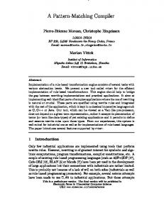
subimages, which represent the horizontal, vertical and diagonal directions of the image, respectively. Figure 1 depicts 1 stage in a multiresolution pyramid decomposition of an image. The detailed 2-D pyramid decomposition algorithm, with periodic boundary conditions applied, can be expressed as follows :
Let M × N = the original image size of f ( x, y ) l (i ) = the analysis lowpass coefficients of a specific wavelet basis, i = 0,1,2,… , N l - 1 , where N l is the support length of the filter L . h( j ) = the analysis highpass coefficients of a specific wavelet basis, 5
j = 0,1,2,..., N h − 1 , where N h is the support length of the filter H . Then, f L ( x, y ) =
1 Nl
f H ( x, y ) =
1 Nh
for x = 0,1,2,… ,
N l −1
∑ l (i) ⋅ f ((2 x + i) mod M , y) i =0
N h −1 j =0
M − 1 and y = 0,1,2,..., N − 1 . 2
1 f LL ( x, y ) = Nl 1 f LH ( x, y ) = Nh 1 f HL ( x, y ) = Nl 1 f HH ( x, y ) = Nh
for x = 0,1,2,… ,
∑ h( j ) ⋅ f ((2 x + j ) mod M , y)
N l −1
∑ l (i) ⋅ f i =0
L
( x, (2 y + i ) mod N )
N h −1
∑ h( j ) ⋅ f
L
j =0
N l −1
∑ l (i) ⋅ f i =0
H
( x, (2 y + j ) mod N )
( x, (2 y + i ) mod N )
N h −1
∑ h( j ) ⋅ f j =0
H
( x, (2 y + j ) mod N )
(1) (2) (3) (4)
N M − 1 and y = 0,1,2,..., − 1 . 2 2
The 2-D pyramid algorithm can iterate on the smooth subimage f LL ( x, y ) to obtain four coefficient matrices in the next decomposition level.
The lowpass coefficients l (i ) and highpass coefficients h( j ) of various wavelet bases such as Haar and Daubechies can be found in references [Daubechies, 1992; Tsai and Hsiao, 2000].
Our primary experiments show that the choice of wavelet
bases has only small effects on the detection results. However, the length of suport of a wavelet basis is crucial for the success of matching.
Due to the boundary effect
of the limited template size, the computation of wavelet coefficient for pixels in the 6
vicinity of window boundaries depends on pixels that lie beyond the boundaries of the template and extrapolation of existing pixel data.
For a wavelet basis with long
support length, the boundary effect is enlarged and poor correlation may be generated in the matching process.
In practice, a wavelet basis with shorter supports such as
the Haar wavelet with a very compact support of 2 and a 4-tap Daubechies wavelet are the best choice for the investigated application.
Wavelet bases with short support
lengths are not only less sensitive to the boundary effect but also more computationally efficient, compared to those with long support lengths.
The reduction factor of an image size is given by 4 J , where J is the number of decomposition levels. For a level 2 decomposition, the size of an original image can be reduced by a factor of 16. matching process.
This results in great computational saving in the
In practice, the effective size of the smallest subimages in the
decomposition should be used as a stopping criterion for determining the maximum number of decomposition levels.
If the decomposed subimage has an
over-downsampling size, the locations and wavelet coefficient values of object features may change dramatically from sample to sample, and generate a false match accordingly. Our experimental results on a variety of test images show that the smallest size of a decomposed template subimage should be larger than 20 × 20 pixels.
The matching process can be performed either on the decomposed smooth subimage or on the decomposed detail subimages at a lower multiresolution level. In this study, we select the detail subimages for the computation of normalized correlation so that only pixels with high energy values in the detail subimages are used as the matching candidates. It alleviates pixel-by-pixel matching in the smooth 7
subimage.
As aforementioned, three detail subimages containing, separately,
horizontal, vertical, and diagonal edge information of object patterns are obtained in one decomposition level.
These three detail subimages are combined as a single
composite detail subimage that simultaneously displays horizontal, vertical and diagonal edge information in the same images.
The composite detail subimage is
given by (J ) (J ) (J ) f d( J ) ( x, y ) = f LH ( x, y ) + f HL ( x, y ) + f HH ( x, y )
(5)
(J ) (J ) (J ) ( x, y ) , f HL ( x, y ) and f HH ( x, y ) are the horizontal, vertical and diagonal where f LH
detail subimages at resolution level J ,respectively. They can be calculated from eqs. (1)-(4).
We use the l1 -norm as the energy function for each pixel in the composite
detail subimage f d( J ) ( x, y ) . Although the l 2 -norm can also be used for the energy function, primary experiments show that the l1 and l 2 norms make little difference in the final results.
The l1 -norm is chosen due to its simplicity in computation.
Given an original image of size M × N, the size of the composite detail subimage f d( J ) ( x, y ) at resolution level J is reduced to ( MJ ) × ( NJ ) . 2
2
The matching process can now be carried out on the composite detail subimage. Since the energy values of most pixels in the detail subimage are approximate to zero, only the pixels with high energy values are considered for further matching. Depending on the complexity of a scene image, the high energy-valued pixels generally dominate only 20 to 30% of the entire composite detail subimage.
The
threshold for selecting high energy-valued pixels can be manually predetermined or adaptively determined by using binary thresholding techniques such as the well-known Otsu’s method [Otsu, 1979]. 8
3.
Ring Projection Representation
Pattern matching basically involves two tasks: pattern representation followed by a matching process based on some similarity measures. In order to reduce the computational burden in the matching process and make the match invariant to rotation, a ring projection transformation is proposed.
It transforms a 2D gray-level
image into a rotation-invariant representation in the 1D ring projection space. The proposed transformation scheme for gray-level patterns is inspired by the ring projection algorithm [Tang et al., 1991; Yuen et al; 1998], which is originally developed for character recognition in binary images.
Let the pattern of interest be contained in a circular window of radius W.
The
radius chosen for the window depends on the size of the reference template.
The
ring projection of the composite detail subimage f d( J ) ( x, y ) is given as follows. First, f d( J ) ( x, y ) in the Cartesian coordinates is transformed into the polar coordinates: x = r cosθ y = r sin θ The ring projection of image f d( J ) ( x, y ) at radius r, denoted by p (r ) , is defined as the mean value of f d( J ) (r cosθ , r sin θ ) at the specific radius r.
p(r ) =
1
2π r ∫
2π 0
That is,
f d( J ) ( r cosθ , r sin θ )dθ
Taking the mean energy value for each specific ring reduces the noise effect and makes the projected values in different ring radii limited to a controlled range. 9
The
resulting p(r ) is equal to the mean energy values as distributed along concentric circular rings.
The discrete form of p(r ) in a search window of radius W is given by p(r ) =
1 nr
∑f
(J ) d
( r cosθ k , r sin θ k )
(6)
k
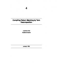
where nr is the total number of pixels falling on the circle of radius r, r = 0,1,2,…,W. Since the projection is constructed along circular rings of increasing radii, the derived 1D ring projection pattern is invariant to rotation of its corresponding 2D image pattern.
Figures 2(a) and 2(b) show a lion image in two distinct orientations.
Figures 2(c) and 2(d) present the plots of ring-projected values as a function of radius r.
It can be seen from the figures that these two ring-projection plots are
approximately identical, regardless of orientation changes.
In the matching phase, the measure of similarity is given by the normalized correlation.
Let PM =< p (0), p (1),..., p (W ) > ,
and ) ) ) PS =< p (0), p(1),..., p(W ) > represent the ring-projection vectors of the reference template and a scene subimage, respectively.
The normalized correlation between ring-projection vectors PM and
PS is defined as W
ρp =
∑ r =0
W
{∑ r =0
) ) [ p (r ) − µ p ][ p (r ) − µ p ] W
[ p (r ) − µ p ] .∑ 2
r =0
where 10
) ) [ p(r ) − µ p ] 2
}
(7) 1
2
µp =
1 W ∑ p(r ) W + 1 r =0
) µp =
1 W ) ∑ p(r ) W + 1 r =0
The correlation coefficient ρ p is scaled in the range between –1 and 1. The computation of correlation coefficient is only carried out for those high energy-valued pixels in the composite detail subimage.
Note that the dimensional length of the
ring-projection vector is only W + 1, where W is the radius of the circular window. This significantly reduces the computational complexity for the correlation coefficient
.
Given an original image of size M × N and the circular window of radius W , the computational complexity of a traditional pixel-by-pixel matching scheme is given by M ⋅ N ⋅ (π ⋅ W 2 ) for objects in each possible orientation. However, for a level J wavelet decomposition, the computational complexity of the proposed matching scheme is reduced to ( M ⋅ N 4 J ) ⋅ (W 2 J ) ⋅ k % for objects in arbitrary orientations, where k % is the percentage of high energy-valued pixels in the composite detail subimage f d( J ) ( x, y ) , and k % < 1. Once the candidate locations of a reference pattern are identified in the composite detail subimage at a lower resolution level, we then verify those candidate locations by computing the correlation coefficients in the vicinity of their corresponding ones in the original (level 0) image. the detected coordinates in the level J detail subimage.
Let ( x * , y * ) be
Then, the corresponding
coordinates of ( x * , y * ) in their level 0 image are given by (2 J x * , 2 J y * ) . If the localization error in one axis is ∆t in the level J subimage, the search region in the original image should be ( x * ± 2 J ∆t ) × ( y * ± 2 J ∆t ) for fine tuning.
Our primary
experiments indicate that the localization error ∆t is generally within 2 pixels and 11
no more than 4 pixels for resolution level J ≤ 2 , and window radius W ≥ 20 .
4.
Experimental Results
In this section, we present the experimental results for evaluating the efficacy of the proposed template matching method. All experiments are implemented on a personal computer with a Pentium III 450 MHz processor. 256 × 256 pixels wide with 8-bit gray levels.
The images are
To illustrate the localization
capability of the proposed method, the matched patterns shown in all figures in this section are based on the detected positions at the low resolution level without fine tuning at level 0. The effects of changes in support length of a wavelet basis, rotation and lighting are first discussed in the subsection that follows.
4.1 Effects of changes in wavelet support length, rotation and lighting
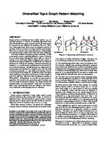
In order to evaluate the effect of a change in the support lengths of a wavelet basis, Figures 3(b), (c), (d) and (e) show the matching results from wavelet bases Haar (support length of 2), D4 (4-tap Daubechies), D8 (8-tap Daubechies) and D12 (12-tap Daubechies), respectively. template.
Figure 3(a) presents the original image of the reference
Figures 3(f), (g), (h) and (i) illustrate the composite detail subimages at
resolution level 1 (J = 1) for Figures 3(b), (c), (d) and (e), respectively. The circles shown in Figures 3(b)-(e) mark the detected locations of the best matches. The matching results reveal that wavelet bases with shorter support lengths such as Haar and D4 (Figures 3(f) and 3(g)) work well for pattern matching tasks. 12
The edge
information in the composite detail subimages obtained from D8 and D12 (Figures 3(h) and 3(i)) is severely distorted due to boundary effects.
The longer the support
length is used, the worse the edge distortion is obtained. Throughout this section, the D4 wavelet basis is used in the subsequent experiments.
It has been verified to
be efficient and robust for many test samples in pattern matching tasks.
The effect of changes in rotation is evaluated using two test images shown in Figures 4 and 5.
The reference templates of a Chinese “one” and a snail image are
marked with squares as shown in Figures 4(a) and 5(a), respectively.
Both test
samples are rotated by 45, 90, and 220 degrees with respect to the original templates. Since the template sizes are 76 × 76 pixels in Figure 4(a) and 56 × 56 pixels in Figures 5(a), the level 1 decomposition is used so that the sizes of decomposed templates are not smaller than 20 × 20 pixels. The detection results are marked with circles and shown in Figures 4(b)-(d) and 5(b)-(d). It can be seen from both Figures 4 and 5 that all instances of reference templates are correctly detected, regardless of rotation changes.
The effect of changes in illumination is evaluated using two test samples shown in Figures 6 and 7. Figure 6(a) shows the reference template of a “Coca-Cola” cap marked with a square. The template size is 130 × 130 pixels and, therefore, the composite detail subimage at resolution level 2 can be used for matching.
Figures
6(b) and 6(c) are the underexposed and overexposed versions of Figure 6(a), respectively. Figures 6(d) and 6(e) present the composite detail subimages at the second resolution level for Figures 6(b) and 6(c).
The detection results are marked
with circles and shown in Figures 6(b) and 6(c).
Figure 7(a) shows one additional
test template of a marble ornament with the size of 70 × 70 pixels (and, therefore, 13
level 1 decomposition is used). Note that the template on the left is similar in appearance to the marble ornament on the right in the image.
Figures 7(b) and 7(c)
are the underexposed and overexposed versions of Figure 7(a), respectively. The detected instances of the template are marked with circles in these two figures.
The
target template is well detected in the underexposed and overexposed images with a minor localization difference.
The experimental results from both Figures 6 and 7
reveal that the proposed pattern matching scheme is robust for detecting objects under varying illumination.
4.2 Industrial applications
In order to further demonstrate the effectiveness of the proposed pattern matching scheme, three object detection applications for IC components, bar-coded strips and license plates are examined in this subsection. In IC component detection, the reference template with larger size of 88 × 88 pixels (Figue 8(a)) is searched on the composite detail subimage at level 2 decomposition.
The template with smaller
size of 72 × 72 pixels (Figures 9(a)) is detected on the composite detail subimage at level 1 decomposition.
Note that both test samples in Figures 8(b) and 9(b) are
rotated approximately by 90 degrees with respect to their reference templates.
As
seen in Figures 8 and 9, the marked circles have reliably identified all desired IC components on the complex layouts of the printed circuit boards.
In the bar-coded strip detection, the main purpose of the application is to locate the position of the strip on a commodity rather than to decode the contents of the bar codes.
The reference templates are marked with rectangular frames as shown in
Figures 10(a) and 11(a). The template size in Figure 10(a) is 100 × 100 pixels, and 14
the level 2 decomposition is used accordingly. The template size in Figures 11(a) is only 74 × 74 pixels and, therefore, the level 1 decomposition is used for matching. The detection results of the two test samples are marked with circles and displayed in Figures 10(b), and 11(b).
It can be seen from Figure 11(b) that there are two
bar-coded strips in the test image.
The proposed method also works well to detect
the target strip.
In license plate detection, we use one arbitrary plate shown in Figure 12(a) as the reference template to detect the locations of different plates on various vehicles, which are shown in Figures 12(b)-(e).
Figure 12(d) shows the plate on a car at the
sloping position, and Figure 12(e) shows the plate on the front of a car. The size of the reference plate is 76 × 76 and, therefore, the composite detail subimage at resolution level 1 is used for matching. in the test images.
All detected plates are marked with circles
Although the characters in the reference plate are different from
those in all test plates, the proposed pattern matching scheme has reliably detected the locations of the plates regardless of the plates on the rear or the front of different cars.
5.
Conclusions
Template matching has been a fundamental technique in machine vision for detecting objects in complex images.
The main limitations of traditional pattern
matching methods are that an enormous number of templates must be matched against an image field to account for changes in rotation of reference templates, and the measure of similarity must be carried out in a pixel-by-pixel manner. 15
In this paper,
we have tackled the problem of pattern matching using the wavelet decomposition and ring-projection representation. The proposed method significantly reduces the number of search pixels by using the composite detail subimage at a low resolution level.
The computation of correlation coefficients is only carried out for those high
energy-valued pixels in the composite detail subimage. The 2D circular window for each high energy-valued pixel in the composite detail subimage is further transformed to a 1D pattern in the ring projection space.
The ring-projection representation not
only reduces the computational complexity of the normalized correlation but also makes the detection invariant to rotation.
Based on the experiments in the previous section, a wavelet basis with short support lengths such as Haar and 4-tap Daubechies should be used in the wavelet decomposition to alleviate boundary effects for pattern matching tasks. The size of the smallest decomposed template should not be less than 20 × 20 pixels, and it should be used as a stopping criterion for further decomposition.
Experimental results have shown that the proposed pattern matching scheme is efficient and robust for detecting complex objects in arbitrary orientations.
However,
the proposed method in its current form is sensitive to scale changes.
It is
worthwhile to extend the proposed method with the multiscale property of the wavelet transform for scale-invariant pattern matching.
16
References
Ahmed, F., Karim, M. A., Alam, M. S., 1995. Wavelet transform-based correlator for the recognition of rotationally distorted images. Optical Engineering 34, 3187-3192. Allen, R. L., Kamangar, F. A.; Stokely, E. M., 1993. Laplacian and orthogonal wavelet pyramid decompositions in coarse-to-fine registration. IEEE Trans. Signal Processing 41, 3536-3541. Chapa, J. O., Raghuveer, M. R., 1995. Optimal matched wavelet construction and its application to image pattern recognition. Proceedings of SPIE 2491/1, Bellingham, WA., 518-529. Crowley, J. L., Sanderson, A.C., 1987. Multiple resolution representation and probabilistic matching of 2-D gray-scale shape. IEEE Trans. Pattern Anal. Machine Intell. 9, 113-121. Daubechies, I., 1992. Ten Lectures on Wavelets, SIAM, Philadelphia, PA. Gonzalez, R. C., Woods, R. E., 1992. Digital Image Processing. Addison-Wesley, Reading, MA. Gross, A. D., Rosenfeld, A., 1987. Multiresolution object detection and delineation. Computer Vision, Graphics, Image Processing 39, 102-115. Maestre, R. A., Garcia , J., Ferreira, C., 1997. Pattern recognition using sequential matched filtering of wavelet coefficients. Optics Communications 133, 401-414. Mallat, S. G, 1989. A theory for multiresolution signal decomposition: the wavelet representation, IEEE Trans. Pattern Anal. Mach. Intell.11, 674-693. Otsu, N., 1979. A threshold selection method for gray-level histogram. IEEE Trans. Syst. Man Cybern. 9, 62-66. Roberge, D., Sheng, Y., 1994. Optical composite wavelet-matched filters. Optical Engineering 33, 2290-2295.
17
Rosenfeld, A., Vanderbrug, G. J., 1977. Coarse-fine template matching. IEEE Trans. Syst. Man Cybern., SMC-7, 104-107. Stone, H. S., Le Moigne, J.; McGuire, M., 1999. The translation sensitivity of wavelet-based registration. IEEE Trans. Pattern Anal. Machine Intell. 21, 1074-1081. Tang, Y. Y., Cheng, H, D., Suen, C. Y., 1991. Transformation-ring-projection(TPR) algorithm and its VLSI implementation. Int. J. Pattern Recog. Artifical Intell. 5, 25-56. Tsai, D.-M., Hsiao, B., 2000. Automatic surface inspection using wavelet reconstruction. Pattern Recognition (to appear). Yoon, S. H., Kim, J. H., Alexander, W. E., Park, S. M., Sohn, K. H., 1998. An optimum solution for scale-invariant object recognition based on the multiresolution approximation. Pattern Recognition 31, 889-908. Yuen, P. C., Feng, G. C., Tang, Y. Y., 1998. Printed Chinese character similarity measurement using ring projection and distance transform. Int. J. pattern Recog. Artifical Intell. 12, 209-221.
18
l (x )
2↓x
f L (x , y )
f (x, y ) h (x )
2↓ x
f H (x , y )
l (x )
2↓y
f LL ( x , y )
h (x )
2↓y
f LH ( x , y )
l (x )
2↓y
f HL ( x , y )
h (x )
2↓y
f HH ( x , y )
2↓ x
: Down sample by 2 along x (row)
2↓y
: Down sample by 2 along y (column)
Figure1. One stage in a multiresolution image decomposition.
19
y 255 240 225 210 195 180 165 150 p(r) 135 120 105 90 75 60 45 30 15 0
x
r
(a)
(c)
y 255 240 225 210 195 180 165 150 p(r) 135 120 105 90 75 60 45 30 15 0
x
r
(b)
(d)
Figure 2. A lion image in two different orientations: (a), (b) the original images; (c), (d) the corresponding ring projection plots of (a) and (b), respectively. Notice the resemblance between (c) and (d).
20
(a)
(b) Haar
(f)
(c) D4 (g) Figure 3. The effect of changes in wavelet support length : (a) the template image ; (b)-(e) the detection results from wavelet bases Haar, D4, D8 and D12, respectively ; (f)-(i) the composite detail subimages at resolution level 1 for respective (b)-(e)
21
(d) D8
(h)
(e) D12
(i) Figure 3. (Continued)
22
(a)
(b)
(e)
(c)
(f)
(d) (g) Figure 4. The effect of changes in image rotation for a Chinese “one ” image: (a) the template marked with a square; (b), (c), (d) the rotated images in 45o, 90o and 220o , respectively (the detected objects are marked with circles); (e), (f), (g) the corresponding composite detail subimages at resolution level 1.
23
(a)
(b)
(e)
(c)
(f)
(d) (g) Figure 5. The effect of changes in image rotation for a snail image : (a) the template marked with a square, (b), (c), (d) the rotated images in 45o, 90o and 220o , respectively (the detected objects are marked with circles); (e), (f), (g) the corresponding composite detail subimages at resolution level 1.
24
(a)
(b)
(d)
(c) (e) Figure 6. The effect of changes in image illumination for a “Coca-Cola” template : (a) the image containing the template marked with a square; (b), (c) the underexposed and overexposed versions of the image ( the detected objects are marked with circles); (d), (e) the corresponding composite detail subimages at resolution level 2.
25
(a)
(b)
(d)
(c) (e) Figure 7. The effect of changes in illumination for a marble ornament template : (a) the image containing the template marked with a rectangular frame; (b), (c) the underexposed and overexposed versions of the image. ( the detected objects are marked with circles); (d), (e) the corresponding composite detail subimages at resolution level 1.
26
(a) (a)
(b) (b)
(c) Figure 9. Detecting an IC component of size 72×72 pixels: (a) the original PCB image; (b) the detected component marked with a circle; (c) the composite detail subimage at resolution level 1.
(c) Figure 8. Detecting an IC component of size 88×88 pixels: (a) the original PCB image; (b) the detected component marked with a circle; (c)the composite detail subimage at resolution level 2.
27
(a)
(a)
(b)
(b)
(c) (c) Figure 11. Detecting a bar-coded strip of size 74×74 pixels: (a) the original image; (b) the detected strip marked with a circle; (c) the composite detail subimage at resolution level 1.
Figure 10. Detecting a bar-coded strip of size 100×100 pixels: (a) the original image; (b) the detected strip marked with a circle; (c) the composite detail subimage at resolution level 2.
28
(a)
(b)
(f)
(c) (g) Figure 12. Detecting license plates on cars: (a) the plate used as the template; (b)-(e) the detected plates marked with circles; (f)-(i) the corresponding composite detail subimages at resolution level 1.
29
(d)
(h)
(e)
(i)
Figure 12. (Continued)
30