Journal of Electrical Engineering www.jee.ro
Rotor broken bar fault detection in Induction Motor Using Transformative Techniques Khadim Moin Siddiqui
Kuldeep Sahay
Institute of Engineering & Technology, Lucknow, INDIA
[email protected],
[email protected]
V.K. Giri Madan Mohan Malaviya University & Technology, Gorakhpur, INDIA
[email protected] Abstract: Induction motors, especially squirrel cage induction motors, have an important role in industry. Their rotor may be failed under stresses depending on their application and get unexpected failure condition during motor operation. If the failure can be detected during its operation i.e. in transient condition then it prevent failure spread and also manufacture trip. The advancement in digital signal processing transformative techniques have enabled researchers to process more data in less time. Consequently, the information that is not previously available can be extracted from the collected data. In the light of these developments, condition monitoring in induction motor using transformative techniques has recently gather more attention from researchers. Earlier, there are many transformative techniques used for rotor broken bar fault detection purpose but each technique had some disadvantages. The most frequent techniques used by the researchers for rotor faults detection purpose, such as Fast Fourier Transform (FFT) and Short Term Fourier Transform (STFT). The FFT based method unable to diagnose rotor fault in the transient condition and in the noload condition. Therefore, some researchers proposed STFT technique which is able to diagnose fault in the transient conditions but faced frequency resolution problem. In the present paper, the rotor broken bar fault has been detected by time domain, frequency domain (FFT) and time-frequency domain (Wavelet Transform) transformative techniques. The wavelet transform technique solved all the above stated problems and detected fault in the transient and all loading conditions. The stator current motor parameter is used for the rotor fault detection purpose. Key words: Squirrel Cage Induction Motors, Time Domain Analysis, Fast Fourier Transform, Wavelet Transform
1. Introduction Continuous and trouble-free operation of induction motors is an essential part of modern power and production plants[1-2]. The faults and failures of electrical machinery may cause remarkable economical losses but also highly dangerous situations. Since, the analysis and design of rotating machinery is critical in terms of the cost of both production and maintenance, it is not surprising that the fault diagnosis of rotating machinery is a crucial aspect of the subject and is
receiving ever more attention. As the design of rotating machinery becomes increasingly complex, as a result of the rapid progress being made in technology, so machinery condition monitoring strategies must become more advanced in order to cope with the physical burdens being placed on the individual components of the machine[3-4]. Therefore, the condition monitoring of induction motors have been a challenging task for the engineers and researchers mainly in industries. There are many condition monitoring methods, including vibration monitoring, thermal monitoring, chemical monitoring, acoustic emission monitoring[8] but all these monitoring methods require expensive sensors or specialized tools whereas current monitoring out of all does not require additional sensors[1,2]. The current monitoring techniques are usually applied to detect the various types of induction motor faults such as rotor fault, short winding fault, air gap eccentricity fault, bearing fault, load fault etc. In current monitoring, no additional sensors are necessary. This is because of basic electrical quantities associated with electromechanical plants such as current and voltage are readily measured by tapping into the existing voltage and current transformers that are always installed as part of the protection system. As a result, current monitoring is non-invasive and may even be implemented in the motor control center remotely from the motors being monitored[2,6]. The Motor Current Signature Analysis (MCSA) uses the current spectrum of the machine for locating characteristic fault frequencies. When a fault is present, the frequency spectrum of the line current becomes different from healthy motor. Such fault modulates the air-gap and produces rotating frequency harmonics in the self and mutual inductances of the machine. It depends upon locating specific harmonic component in the line current [1,3,11-14]. During direct-on-line (DOL) starting, the rotor current of the induction machine is very high. Under
1
Journal of Electrical Engineering www.jee.ro
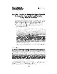
these conditions, rotor faults should be much more evident than under normal running conditions. There is also the advantage that the starting current is less sensitive than the running current to the level of motor load, and so reliable data analysis can be obtained even with motors with no mechanical load[6]. The two drawbacks in dealing with the starting current are firstly the motor speed is constantly changing during starting which means the fault related signal frequency components are changing in both amplitudes and frequency, and secondly the starting current only occurs for a short time. The starting time, which depends upon the total inertia of the motor and the load, may vary from a fraction of a second for small motors, up to several seconds for large motors [1,10]. Therefore, due to the transient nature of the signal, conventional FFT analysis is not suitable for analysing starting currents. Although Short Time Fourier Transform (STFT) can be used for analysing transient signals using a time-frequency representation, it can only analyse the signal with a fixed sized window for all frequencies, which leads to poor frequency resolution. However, wavelet techniques can overcome this problem by using a variable sized window [5,7,10,12]. A wavelet technique for detecting broken rotor bars in induction motors has been reported in [11,15-17]. A new method was reported for rotor broken bar fault detection purpose in transient condition. it was based on improved root-music approach[7]. But this method also does not diagnose rotor fault in the no-load conditions. Finally, It has been observed that from the previous researches. The FFT based method can not be used in the variable load conditions and unable to diagnose fault in the transient conditions. It has also been observed that the FFT based method does not diagnose rotor fault in the no-load conditions. In the present paper, the rotor broken bar fault has been diagnosed in the time domain, frequency domain and time-frequency domain transformative techniques. The obtained results solved all the above mentioned problems and diagnosed rotor fault in the transient condition for various loads. 2. Time Domain Analysis The 0.5 HP, 415 V, 1725 rpm squirrel cage inverterfed induction motor is used for the analysis in present work. The fundamental frequency of the motor is 50 Hz and inverter frequency is 60 Hz. The block diagram of the experimental set-up is as shown in Fig 1. In the presnet paper, we will concentrate towards stator current motor paramter for fault diagnosis purpose because it does not require costly sensors.For Motor Current Signature Analysis(MCSA) only current transformer is required which is pre-installed with
motor.This tecnique is very flexible with lower cost.
Fig. 1. Block Diagram of Experimental Set-up First, we have done time domain analysis and observed the transient characteristics of the motor. The same rating motor is applied for healthy as well as faulty motor. The responses of the healthy motor and faulty motor will be different. The healthy motor may be considered as faulty motor by varying some physical parameters such as slip and load torque. The mathematical modeling has been done of the three phase squirrel cage induction motor [18].In this particular analysis, we can diagnose broken rotor bar in time domain from various motor signatures of IM but widely used are stator current, rotor current, rotor speed and electromagnetic torque. The motor signatures for healthy condition are as shown in Fig 2
(a)
(b)
(c) (d) Fig. 2. Healthy condition of the motor, (a) Rotor current, (b) Stator current, (c) Rotor speed, (d) Electromagnetic torque We can observe from the fig 1(a) to (d) that the stator current, rotor current, rotor speed, electromagnetic torque all are reached in the steady state condition after 0.8 seconds.. The steady state electromagnetic torque is achieved 11.9 N-m as can observe from fig 1(d). The 11.9 N-m is nominal full load torque. In the healthy condition of the motor, the slip is set at 1(s=1) and nominal full load torque 11.9 N-m. It means rotor is in standstill condition. Therefore; all the motor parameters give rated value. The comparison is made for healthy and faulty condition of the motor for different loading conditions. In both the cases, the first maximum
2
Journal of Electrical Engineering www.jee.ro
transient peak of the motor parameters has been observed for early fault detection purpose. The first maximum transient peak variations for 5-broken bar conditions are as shown in table 1.
given in the Table 2 are decreased except electromagnetic torques value it is slightly increased. It is concluded that if the rotor fault severity is increased then electromagnetic torque also will be increased. The TABLE: II Comparison of Various Broken Bars Parameters MC
(a)
Healthy 1 1 BRB 0.04 3 BRB 0.056 5 BRB 0.08 No-Load 0.01 BRB: Broken Bar
(b)
(c) (d) Fig. 3. Faulty conditions (5-broken bar at full load),(a) Rotor current, (b) Stator current, (c) Rotor speed, (d) Electromagnetic torque The motor signature variations for 5-broken bar faulty conditions are shown in fig 3(a) to (d). it has clearly been observed from the fig 3 that the motor transient characteristics has been disturbed. Therefore, motor has been unbalanced. TABLE: I Comparison in Faulty Motor Conditions at Different Load (5-broken bar) MC
Slip
TMPRC (A)
TMPSC (A)
RS (rpm)
Slip
TMPEMT (N-m)
H-Y 1 74.53 87.07 1725 90.64 N-L 0.01 59.83 78.02 1485 53.07 H-L 0.04 55.43 77.79 1440 54.92 F-L 0.08 49.02 77.52 1380 55.83 MC: Motor Condition, H-Y: Healthy N-L: No-Load, H-L: Half-Load, F-L: Full-Load, TMPRC: Transient Maximum Peak Rotor Current, TMPSC: Transient Maximum Peak Stator Current, TMPEMT: Transient Maximum Peak Electromagnetic Torque (N-m),
The comparison in faulty motor conditions for various broken bar is as shown in Table 2. This comparison clearly shows the difference between 1, 3, 5 broken bars in the motor parameters. The comparison is made from healthy motor parameters. The analysis is also done for no-load condition of the motor. It is observed from the table 2, when the rotor bar is broken at that time all the motor parameters are decreased but when the rotor broken bar is increased then the parameters of the motor is being decreased except electromagnetic torque. It is clearly indicated in the table 2 that when the first rotor bar is broken then at that time stator current maximum peak value is 77.74 A whereas, in healthy condition it is more than the faulty stator current i.e. 87.07 A. If bar broken is increased then fault will be severe and stator current will be further decreased. It is observed that all the mentioned signatures of the motor
TMPRC (A) 74.53 54.56 52.68 49.02 59.83
TMPSC (A) 87.07 77.74 77.68 77.52 78.02
RS (rpm) 1725 1440 1416 1380 1485
TMPEMT (N-m) 90.64 55.29 55.59 55.83 53.07
Rotor speed is also decreased. It is concluded that from the above tables the signatures of the motors in the healthy condition is completely different from the faulty condition of the induction motor due to non-invasive nature. Since, in the healthy condition the rotor speed is 1725 rpm when inverter frequency is 60 Hz. For, 50 Hz inverter frequency the rotor speed is 1430 rpm. The combined response of the three phase squirrel cage induction motor for healthy and faulty (5-broken bar) condition is as given in figure 4(a) and (b). It shows clear variation between the signal magnitudes verses time for healthy and faulty motor. Now, it is clear that using time domain responses it is possible to detect rotor faults in all load conditions but we cannot have any frequency information, a lot of signal information is hidden in the form of frequency. Therefore, the Fast Fourier Transform (FFT) technique is used to overcome this problem. It gives frequency information and it was used for the rotor bar broken purpose in our applications.
(a)
(b)
Fig. 4. Combined response, (a) For healthy condition (b) for 5 broken bar condition at full load 3. Application of Fast Fourier Transform (FFT) Due to the advancement of digital signal processing techniques the role of frequency in the signal become very important part of the detection of the rotor fault in the induction machine. The fast Fourier transform is the advance version of the discrete Fourier transform, the data computing time is less in the FFT than discrete Fourier transform. The FFT algorithm is widely used for the detection of rotor broken bar fault. It is possible to find out power spectral density of the motor stator
3
Journal of Electrical Engineering www.jee.ro
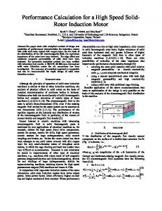
current. The stator current shows the side bands around the fundamental frequency. The fundamental frequency of the motor is 50Hz. If any fault is occurred then amplitude of the side lobes are increased that is clear indication of fault. It is due to the reverse rotating magnetic field in the inductor and mutual inductance. The power spectrum of healthy motor is shown in fig 5.
detection of fault for one rotor broken bar condition in the half-load condition. In spite this drawback if we analyse fault detection for more broken bars motors such as for 5 and 12. It may be successfully used and side lobes fault frequencies are clearly visualized as shown in fig 6. The power spectrums for various broken bars at noload condition are as shown in fig 7. It is observed that in the no-load condition the sidelobes amplitude are very small around the fundamental frequency therefore; it looks like same as the response of healthy motor. From this method, at no-load condition is almost impossible to detect rotor broken bar fault.
Fig. 5. Power Spectrum of Healthy Motor Power spectrums of healthy motor and for various broken bars at half load conditions are given in fig 6.It has been observed that from the results that the sidelobes around the fundamental frequency are visualized and fault frequencies are 46 Hz and 54 Hz respectively. It is noted that the fault frequency is unique for all broken bars of the motor.
Fig. 6. Power Spectrums at Half-Load Conditions If we compare the results which are obtained for 1,5 and 12 broken bars condition at half-load from the healthy motor response. Both responses are different. Therefore, it may be concluded that at the half load condition of the motor, FFT method is suitable for rotor fault detection purpose for all broken bar conditions. Since, in the half-load condition the side lobe around the fundamental frequency is very small and is not easily visualized. Therefore, it is quite difficult for the
Fig. 7. Power spectrums at no-load conditions The power spectrum at full load condition is as given in fig 8 for the different rotor broken bars. It is clearly observed when the rotor broken bar is increased then the amplitude of the sidelobes around the fundamental frequency is increased. It is also observed that fault frequencies are unique for all the loading condition as can be observed from the full load fig 8. All the power spectrums are generated from the motor stator current sometimes it is also called Motor Stator Current Signature analysis (MCSA). This analysis is successfully used in the rotor fault detection for various loading conditions except no-load. FFT based power spectrum method is only used for the steady state analysis it is not used in the transient analysis. An another drawback of this method is that it can not successfully used when the load is varied. It is only applicable for constant load. The transient analysis is done by the two methods of signal processing transformative techniques one is STFT and other is wavelet transform. The STFT technique faced some sort of drawbacks, it has constant window in all the
4
Journal of Electrical Engineering www.jee.ro
frequencies therefore has resolution problem.
shows it has 11detailed signals and final approximation signal. Detailed signal contains high frequency information and approximation signal contains low frequency information. The 11th level approximation signal contains frequency band 2.44 to 1.22 Hz. It is very low frequency and diagnose rotor broken bar fault correctly. It is observed that the final approximation signal of the healthy and faulty motor is completely different.
Fig. 9(a). Full Level Decomposition of Healthy Motor
Fig. 8. Power Spectrums at Full Load Conditions The wavelet transform is successfully used in the early fault detection of the motor because it has variable window size at different frequencies. Therefore, the rotor fault detection using wavelet transform is carried out in the next section. 4. Rotor Fault Diagnosis with Wavelet Transform The rotor fault diagnosis using wavelet transform is widely used in these days. The results obtained from the wavelet transform for rotor broken bar are as shown in fig 9. The full level decomposition of healthy and faulty motor is as shown in fig 9.The sampling frequency is set at 5 KHz. The original signal s is decomposed at the 11th level of decomposition. The signal is decomposed in the two signals one is approximation signal and other is detailed signal. Each signal has its own frequency band. The detailed signal contains high frequency information and approximation signal contains low frequency information. The 11 level decomposition has been performed here in order to extract low frequency information. It is recommended to use high decomposition levels. For lower levels the mother wavelet is located more in time and oscillates faster in a short period of time. A Debauchees (db-10) mother wavelet is used in this work .There is no set rule exist to use the mother wavelet. The advantage of Debauchees mother wavelet is, it is most stable and during reconstruction of the signal from the wavelet coefficients it does not loose any information. As the wavelet goes to higher levels, it is located less in time and oscillates less due to the dilation nature of the wavelet transform. Therefore, fast and low type of faults can be detected with one type of wavelet. It is observed that from the fig 9(a) and 9(b). That
Fig. 9(b). Full Level Decomposition of Faulty Motor(5rotor broken bar) The separate decomposition of the source signal is as shown in fig 10(a) and (b). It has been observed that in the ninth level approximation signal, there is not much change just looks like as the source signal but the 10 th level and 11th level approximation signal contained some useful information. The approximation signal has correct shape to find out rotor broken bar. Therefore, the 11 th level approximation signal is used for the medium of diagnose for the broken rotor bar fault purpose.
Fig. 10(a). Separate decomposition for healthy motor
Fig. 10(b). Separate decomposition for faulty motor The fig 9(a and b) and 10(a and b) are the results of full load condition. Now we will see the approximation signal at the different loading conditions. These results
5
Journal of Electrical Engineering www.jee.ro
are involved in the tree so commonly called tree method. From these results, we can analyze the rotor broken bar at different load. The approximation signal for healthy condition and rotor broken bar fault condition at half load, full load and no-load condition are given in fig 11(a-d). From these results we can understand the difference between the healthy and faulty results. First see the result for healthy condition of the motor in fig 11(a), this diagram contains three signals: one is source signal, wavelet decomposition tree and finally approximation signal that
(a)
(b)
(c) (d) Fig. 11 (a). Approximation signal for healthy condition, (b) Approximation signal at full load condition, (c) Approximation signal at half load condition, (d) Approximation signal at no-load condition is used for the rotor fault diagnosis purpose. In the decomposition tree, the source signal is decomposed and get two signals those are called first level approximation and first level detail signal respectively. This decomposition is continued at level 11. There we can have 11th detail and 11th approximation signal. Since the 11th level approximation signal contains low frequency information so, we can diagnose fault very easily from final approximation signal, that fault is involved at low frequency information. From the fig 11 (a - d), It is observed that the entire figures is used for fault diagnosis of rotor broken bar; all the results are different from each other. Observe the result shown in fig 11(d), the result is shown for no-load condition there is much deviation in the stator current. In the other results there is small change in the stator current. It is a non-invasive technique of rotor broken bar fault detection, if we want to see waveform for fault diagnosis then observe the beginning and end point of the approximation signal, there we have observed distortion in the approximation signal waveform as per the nature of the result. The superimpose waveforms for healthy and faulty motor (5-broken bar) for full load is as shown in fig. 12 (a) and (b)
(a)
(b)
Fig.12 (a). Superimpose Waveform in Healthy Condition,(b)Waveform in Faulty Condition After observing superimpose waveforms we can easily observe the difference between the healthy and faulty motor. It is observed that in both the figures, the waveform of faulty motor is completely different from the healthy motor. Therefore, it is concluded that the wavelet transform is successfully used for the fault detection of rotor broken bar from various ways. V. CONCLUSIONS In this paper, the rotor fault detection of induction motor based on Time domain, FFT, and wavelet analysis of stator current are discussed with some experimental results which are useful for online diagnosis in industrial applications. It has been observed that from the obtained results by transformative techniques that The FFT method successfully used to diagnose rotor broken bar fault in the steady state condition not in transient condition. Two more drawbacks of the FFT method are that it is not suitable for variable load condition and noload condition. It has been observed that in the no-load condition the sidelobes around the fundamental frequency are not visualized. Since, it is a non-invasive technique of the rotor broken bar fault detection. Therefore, the sidelobe frequency must be visualized. Therefore, some researchers proposed STFT technique for rotor broken bar fault detection purpose in the transient condition with time-frequency localization. But, STFT shows frequency resolution problem because it shows constant window size for all frequencies..In the present paper, the rotor broken bar fault has been diagnosed in the transient condition with improved resolution by Wavelet Transform(WT). The WT technique has been used to detect rotor broken bar fault in the transient condition with low frequency approximation signal. The low frequency approximation signal gives correct results for faulty broken bar at different loading conditions. The WT shows different window for all frequencies. It does not face resolution problem through multi-resolution analysis.
6
Journal of Electrical Engineering www.jee.ro
REFERENCES [1] Siddiqui, K.M., and Giri,V.K: Broken Rotor Bar Fault Detection in Induction Motors using Wavelet Transform. In: Conf Proc, IEEE, Computing, Electronics and Electrical Technologies [ICCEET], March, 2012,p. 1-6, Chennai, India. [2] Benbouzid, M.E.H.: A Review of Induction Motors Signature Analysis as a Medium for Faults Detection .In: IEEE Transactions on industrial electronics, vol. 47, no. 5, Oct., 2000. [3] Benbouzid, M.E.H.: Bibliography on induction motors faults detection and diagnosis. In: IEEE Trans. Energy Conversion, vol. 9, no.4, Dec., 1999, p. 1065–1074, [4] Hakan Calis and Abdulkadir Cakir: Experimental study for sensorless broken bar detection in induction motors. In: Elsevier, Energy Conversion and Management vol. 49, 2008, p. 854–862. [5] Radhika,S., Sabareesh, G.R., Jagadanand, G. and Sugumaran,V.:Precise wavelet for current signature in 3φ IM. In: Expert Systems with applications, vol.37, no.1, 2010, p.450–455. [6] Bonnet, A. H., Al-Ahmar, M.E.H, Benbouzid and Turri, S.: Cause and analysis of stator and rotor failures in three-phase squirrel-cage induction motors. In: IEEE Trans. Ind. Applicat., vol. 28, July/Aug.,1992, p. 921–937. [7] Boudinar A .H., Bendiabdellah A., Benouzza N. and Boughanmi N.: Three Phase Induction Motor Incipient Rotor’s Faults Detection Based On Improved Root-Music Approach. In: Journal of Electrical Engineering (JEE),vol.7, no.7, 2007, p.100-107. [8] O.I. Okoro: Steady and Transient States Thermal Analysis of a 7.5-kW Squirrel Cage Induction Machine at rated-load Operation. In: IEEE Transactions On Energy Conversion, vol. 20, no.4, Dec. 2005, p. 730-736. [9] Song M. H., Kang E. S., Jeong C. H., Chow M.Y. and Ayhan B.: Mean Absolute Difference Approach for Induction Motor Broken Rotor Bar Fault Detection. In: SDEMPED 2003, Symposium on Diagnostics for Electric Machines, Power Electronics and Drives, Atlanta. CA, USA, 24-26 August 2003, p. 115 – 118. [10] Schoen, R. R., Habetle, T. G. and Brandlein, J.: Effects of time-varying loads on rotor fault detection in induction machines. In: IEEE Trans. Ind.Applicat., ,Vol. 31, July/Aug., 1995, p.900–906. [11] Schoen, R. R. and Habetle, T. G. : Evaluation and implementation of a system to eliminate arbitrary load effects in current-based monitoring of
induction machines. In: IEEE Trans. Ind. Applicat, vol. 33, Nov./Dec.1997, p. 1571–1577. [12] B.,Aruna Kumari, K.Naga, Sujatha and K.Vaisakh: Assessment of Stresses induction motor under different fault conditions. In: Journal of Theoretical and App Information Technology, 2009. [13] Zhang Jian wen, Zhu Ning-hui, Yang Li and Yao Qi, Lu Qing: A Fault Diagnosis Approach for Broken Rotor Bars Based on EMD and Envelope Analysis: In: Journal of China University Mining & Technology, vol.17, no. 2, 2007, p. 205-209. [14] Filippetti F., Franceschini G. Tassoni, C and Vas, P.: Broken bar detection in induction machines: comparison between current spectrum approach and parameter estimation approach. In: Industry Applications Society, vol. 10, 1994, p.95-102. [15] P. S. Meliopoulos and C. H. Lee: Wavelet based transient analysis. In: IEEE Transact. Power Delivery, Vol., 2000, p. 19–121. [16] P. F. Ribeiro: Wavelet transform: An advanced tool for analyzing non-stationary harmonic distortions in power systems. In: Conf Proc. IEEE Harmonics in Power Systems, 1994, p. 91–99. [17] Askari, M.R.: Broken bars detection in squirrel cage induction motors using wavelet theory. In: Journal of Applied sciences, vol. 10, no.6, 2010, p.471-478. [18] Ritchie, E., Deng, X. and Jokinen, T.: Dynamic model of three-phase squirrel cage induction motors with rotor faults. In: Conf Proceedings of the ICEM, IEE Publication, 1994. p. 694–698.
7