Jun 3, 2009 - [12] George Michelogiannakis, James Balfour, and William J. Dally. Elastic buffer flow control for on- chip networks. In HPCA '09: Proceeding of ...
Stanford University Concurrent VLSI Architecture Memo 125
Router Designs for Elastic Buffer On-Chip Networks George Michelogiannakis and William J. Dally Computer Systems Laboratory, Stanford University, Stanford, CA 94305 {mihelog,dally}@cva.stanford.edu 3 June 2009 Abstract This paper explores the design space of elastic buffer (EB) routers by evaluating three representative designs. We propose an enhanced two-stage EB router which maximizes throughput by achieving a 42% reduction in cycle time and 20% reduction in occupied area by using look-ahead routing and replacing the three-slot output EBs in the baseline router of [12] with two-slot EBs. We also propose a single-stage router which merges the two pipeline stages to avoid pipelining overhead. Compared to it, the enhanced two-stage router has a 32% increase in zero-load latency when operated at the same clock frequency; moreover, the single-stage router reduces the required energy per transferred bit and occupied area by 29% and 30% respectively, compared to the enhanced two-stage router. However, the cycle time of the enhanced two-stage router is 26% smaller than that of the single-stage router.
1
Introduction
With the recent scaling in semiconductor technology, more processing and storage elements may be integrated on the same die. Networks-on-chip (NoCs) provide a scalable communication infrastructure [2,4]. As designs get larger, the effect NoCs have on the overall design increases. Thus, increasing network efficiency is essential. This paper explores the design space of elastic buffer (EB) routers. EB routers are bufferless packetswitched routers. They have the area and energy benefits of circuit-switched routers, without the latency and cost overhead of setting up and tearing down circuits. EB routers operate by using master and slave latches of flip-flops (FFs) as independent storage locations [12]. Therefore, the pipeline FFs in channels are used for buffering, in place of input buffers at routers. We evaluate three representative EB router designs. The baseline two-stage router was initially presented in [12]. While simple, it requires a three-slot EB at each output to handle flow-control digits (flits) crossing the switch because arbitration is performed one cycle in advance. Moreover, routing and output arbitration are performed serially. Our first proposed design, the enhanced two-stage router, replaces the intermediate pipeline registers and output EBs with two-slot EBs to reduce cycle time and thus increase throughput in absolute time. A synchronization module maintains alignment between grants and flits. Moreover, lookahead routing [6] is used so that output arbitration is performed in parallel with routing. Finally, our second proposed design, the single-stage router, merges the two stages of the enhanced two-stage router to avoid pipelining overhead and reduce router latency. The enhanced two-stage router reduces cycle time by 42% compared to the baseline two-stage router. It also occupies 20% less area. The single-stage router occupies 30% less area and requires 29% less energy per transferred bit than the enhanced two-stage router. However, it has a 33% increased cycle time compared to the enhanced two-stage router. In our network setting and with each router operating at its maximum frequency, the single-stage router offers comparable (1% less) zero-load latency in absolute time compared 1
Width
Input
D
Data
Q
Master Latch
Q D Slave Latch
Enable
Enable
ENM
Data
ENS V_out
V_in R_in
Output
EB Control Logic
R_out
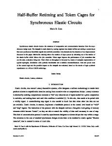
Figure 1: An elastic buffer. to the enhanced two-stage router. Assuming an equal clock frequency, the enhanced two-stage has a 32% increased zero-load latency compared to the single-stage router. The optimal router choice depends on the clock frequency used for the routers. If all routers operate at the same clock frequency, the single-stage router is superior in terms of area and latency. If each router operates at its maximum frequency, the optimal choice for area is the enhanced two-stage router. The baseline two-stage router provides the smallest energy per transferred bit. However, it is very close to the single-stage router which is preferrable in terms of cycle time, latency and area. The choice for designs prioritizing latency can depend on how the channel latency in clock cycles is affected by the clock frequency increase. The rest of the paper is organized as follows: Section 2 outlines related work. Section 3 provides an overview of EB flow-control. Section 4 presents the three EB router designs in detail. Section 5 provides evaluation methodology and results. Section 6 discusses the results and provides insights. Finally, section 7 concludes this paper.
2
Related Work
The first router architectures explored for NoCs focused on virtual channel (VC) flow-control [1]. Past work proposed look-ahead routing [6] and speculative allocation allowing allocators or router stages to be bypassed [8, 14]. Express virtual channels [10] allow the router pipeline to be bypassed. Further work has explored more optimizations such as dynamic VC buffer allocation and other aspects, such as faulttolerance [7, 15]. Asynchronous NoCs and router designs based on VC flow-control have also been proposed [18]. Routers for other flow-control schemes have been explored as well. Hybrid EB–VC networks using elastic channels in addition to input buffers at routers have been explored [9]. Other hybrid router schemes combining VCs or wormhole with circuit-switching by establishing a connection between frequent communication pairs have also been proposed [5, 13]. Routers with both best-effort and guaranteed traffic services have been investigated [17]. Furthermore, bufferless circuit-switched routers have been explored. They can avoid dropping packets by emitting them in a non-ideal direction, also called deflection routing [16], and can provide guaranteed throughput and multicast support [11]. Our work extends previous work in that it performs a design space exploration of EB routers, by proposing and evaluating two new designs. Therefore, the gains EB networks offer in contrast to the currently-dominant VC flow-control are increased compared to [12].
2
3
EB Overview
EB flow-control uses the pipeline FFs in the channels for buffering. The addition of control logic to control the latch enable pins of a master-slave FF separately enables their use as independent storage locations. Thus, each FF becomes an EB with two storage locations. The control logic can be implemented with a four-state finite state machine (FSM) [12]. EB channels feature multiple EBs to form a distributed FIFO. An EB is illustrated in Figure 1. Flits advance to the next EB using a ready–valid handshake. An incoming ready (R) signal indicates that the next EB has at least one free storage location to store an additional flit. An outgoing valid (V) signal indicates that the flit currently being driven by the EB is valid. Flits advance when both ready and valid signals are asserted between two EBs at a rising clock edge. Since flow-control is applied on a per-flit basis, control logic is amortized over the width of the channel. Using channels for buffering enables the removal of router input buffers. Removing router input buffers removes a significant part of the overall network energy and area costs. Moreover, this removes VCs [1] and credits from the network, compared to VC flow-control networks. In a router, this removes credit channel ports and logic as well as the VC allocator. Furthermore, it replaces the switch allocator with a switch arbiter for each output, since each input may request only one output. The area and energy savings from the simplified router design are traded for an increased datapath width to compensate for the decreased channel utilization due to the removal of the input buffers. The ready–valid handshake is used to advance flits within the router. Further overhead, such as VC identifiers and credit channels and logic, are also removed. The FIFO nature of the channels provides no isolation between traffic. Deadlock prevention is achieved by duplicating physical channels and preventing packets from being interleaved [12]. The latter is achieved by performing switch arbitration on a per-packet basis in EB routers.
4
Router Architecture
This section describes the three router designs evaluated in this paper. Section 4.1 outlines the baseline two-stage router of [12]. Section 4.2 describes the enhanced two-stage router. Finally, section 4.3 describes the single-stage router.
4.1
Baseline Two-stage Router
A block diagram of the baseline two-stage EB router of [12] is shown in Figure 2. Only one input and one output are illustrated in detail. This router represents a straightforward design which resembles in operation buffered packet-switched networks. Incoming flits are stored into the input EB. The first pipeline stage consists of routing computation (RC) and switch arbitration (SA). A valid signal from the input EB indicates that a valid flit is driven in the first stage. The head flit’s routing information goes through routing computation. Non-head flits of the same packet use the same selected output, stored in destination registers. When a flit receives a grant, it advances to the intermediate pipeline register. A ready signal is driven back to the input EB to release the flit. The switch arbiters temporarily de-assert their grant as long as their output EB is non-ready. The second stage consists of switch traversal (ST) for flits which won arbitration in the previous cycle. Because arbitration is performed a cycle in advance of switch traversal (and without credits), an extra storage slot is required at the output EB to cover the pipeline delay. Each three-slot output EB de-asserts its ready output if it has two or more flits stored. The third slot is used to store any flit in transit when ready gets de-asserted. However, if an output EB contains two flits and its ready output was de-asserted during the previous cycle, there can be no flit in transit and it can therefore assert its ready output for one cycle. Due to the complexity of the control logic for an EB with three latches, the output EB is implemented as a FIFO using a register file with rotating read and write pointers. Shift registers generate the read and write pointers pointing to one of the three storage locations, while combinational logic handles the rest of the output EB’s inputs and outputs.
3
V
Dest. reg RC EB
SA R
V
V
V
EB
Input R Buffer
Intermediate Register
Output Buffer Output unit
Input unit
Figure 2: The baseline two-stage router. Sel. out. EB
V
SA
Sync module
R
R Logic
EB Input Buffer
EB
V R LA R
Interm. Buffer
V
EB Output Buffer Output unit
Input unit
Figure 3: The enhanced two-stage router. The baseline two-stage router, while simple, has a long critical path in the first stage because routing and arbitration are performed serially. Moreover, the output EB introduces complexity and further area and energy overhead because it is implemented as a FIFO. This is an obstacle in meeting the output port timing constraints to drive the long network channel.
4.2
Enhanced Two-stage Router
The enhanced two-stage router is illustrated in Figure 3. It maximizes throughput in absolute time by minimizing the cycle time. The first difference with the baseline router is that the intermediate register and output EB are replaced with two-slot EBs. This makes the output EBs less costly in terms of area and energy. It also reduces their complexity and thus allows them to meet tighter output port timing constraints, thus enabling the router to operate under smaller cycle times. Furthermore, to remove the routing computation from the critical path of the first stage, we use look-ahead routing (LA R) [6]. Head flits enter the first stage containing their selected output. Therefore, switch arbitration can begin as soon as the head flit arrives, without waiting for routing computation. The look-ahead routing logic calculates the packet’s output at the next hop and inserts it in the head flit via concatenation. No other architectural optimization is possible compared to the baseline two-stage router design since EBs have to remain exactly two-slot to prevent unecessary pipeline bubbles (for less slots) and to prevent excessive implementation cost (for more slots). Moreover, moving the switch arbitration logic to the second stage would essentially result in the single-stage router, explained in section 4.3. The small number of design parameters to explore reflects on the simplicity of EB routers. Flits advance to the intermediate EB even without receiving an output grant, as long as the intermediate EB is ready. Therefore, extra care must be taken to maintain alignment between flits arriving at the second stage and their grants. This is achieved by the synchronization module (sync module). It maintains the selected output ports for the flits stored in the intermediate EB in a separate selected output EB. The 4
Second case
First case
Sel. output
B
Sel. output
A
(O) (O) (O)
Sync mod. EB
Transition at next cycle
C
B
(H)
(H)
B Stage 1 flit
A
B
C (O)
B
(O) (O)
A
A
(H) (H)
Stage 1 flit
Interm. Buffer
A
(T) (H)
Interm. Buffer
The new head flit (B) will remain in stage 1. The chosen output bits will be enqueued next cycle. H: head flit. T: tail flit. O: selected output.
Three different singleflit packets.
Figure 4: Synchronization module operation. selected output port contained in the head of the selected output EB is always that of the current packet (oldest to have flits remaining in the first stage or the intermediate EB). The selected output EB may also contain the selected output port of the next packet as shown in Figure 4 (left). In the worst case, only the tail of the current packet remains and there are two more single-flit packets. The most recent to arrive is contained in the intermediate EB, and the other is driven in the router’s first stage. In that case, the selected output EB stores the current packet’s selected output port at its head and the next packet’s selected output port at its tail (master latch). The third packet’s selected output port is driven as an input. It will be enqueued when the third packet is enqueued into the intermediate EB, a cycle after the tail flit of the current packet departs. The synchronization module detects when the current packet’s tail is about to depart from the intermediate EB and propagates the selected output port of the next packet to the switch arbiters. This is done one cycle in advance of the next packet being able to traverse the switch, as shown in Figure 5. Arbiter outputs are registered to shorten the critical path such that it does not extend past the router first stage. Thus, propagating one cycle in advance is necessary to avoid creating bubbles. Depending on the next packet’s time of arrival, it may either have its head flit stored in the intermediate EB, or driven in the first router stage. In the former case, the next packet’s selected output port will be stored in the selected output EB. In the latter case, the selected output port will be driven as an input to the selected output EB. However, if the next packet’s head flit has remained in the first stage for more than one cycle because the intermediate EB is full, the selected output EB is non-empty because there is no intervening packet, and the next packet’s selected output port will be stored in the selected output EB. This is illustrated in Figure 4 (right). The synchronization module propagates the selected output port of the next packet from the appropriate location, knowing if the intermediate and routing EBs are full (non-ready) or empty (non-valid). Flits at the head of the intermediate EB traverse the switch if they have a grant from their selected output and that output’s EB is ready. Grants are made on packet boundaries and then gated by the selected output EB ready input. When a tail flit is traversing the switch, that input’s synchronization logic asserts an update signal to all outputs. An output which receives an update signal from the input it is granting has its grant registers clocked at the next clock edge, thus updating the grants driven to the other router components. This is illustrated in Figure 5. Arbiters also have their grant register clocking enabled if they are currently granting no input, to assure that grants for newly-arrived packets will be propagated. An extra storage slot in the output EBs is not required because the decision to have the flit traverse the switch is made on the same cycle as it would arrive at the output EB.
5
Cycle 1
Cycle 2
Clk Is tail Is granted Update Grants Requests Previous packet's Next packet tail departs. traverses switch.
Figure 5: Updating output grants. V SA R EB
V
V
Input R LA R Buffer
Dest. reg
EB Output Buffer Output unit
Input unit
Figure 6: The single-stage router.
4.3
Single-stage Router
The single-stage router is shown in Figure 6. It prioritizes latency instead of throughput and avoids pipelining overhead by merging the two stages of the enhanced two-stage router. Incoming flits request their selected output, calculated in advance by the previous router. Grants can only be given for outputs with ready output EBs. The grants from the switch arbiters enable the appropriate flits to traverse the switch and enter the output EBs. Look-ahead routing is performed in parallel, in the same manner as the enhanced two-stage router.
5
Evaluation
The section presents evaluation results for the three EB router designs. Section 5.1 explains the evaluation methodology. Section 5.2 presents the results.
5.1
Methodology
Implementation results were obtained by synthesizing a single instance of each router design using Synopsys Design Compiler and placing and routing the synthesized netlists using Cadence Silicon Encounter. Clock frequencies were determined by static timing analysis using post place and route parasitics. Energy per transferred bit results were calculated by simulating the placed and routed netlists to record activity under
6
an equal cycle time and flit injection rate for all cases, then multiplying by simulation time and dividing by the number of flits and flit size in bits. We used a commercial 45nm low-power library under worst-case conditions. The initial floorplan utilization was set to 70%. Primary input and output driving strengths, loads and timing constraints were specified to realistically assume network channels at the router ports. The network we assumed was an 8×8 mesh using routers of radix 5 with a single network terminal attached to each router. Router ports were placed in the floorplan according to the inter-router connections of the assumed network. Deterministic dimensionordered routing (DOR) was used. Round-robin arbiters were used for switch arbitration. The switch was implemented using multiplexers. Therefore its area and energy cost increases linearly with the number of incoming and outgoing wires, in constrast with the quadratic increase of a tri-state-based crossbar. The network throughput data points were generated using a modified version of booksim [3] for EB networks. No communication protocol was assumed. Thus, there could be no protocol deadlocks. Therefore, we used a single physical 8×8 mesh network defining a single traffic class. We used the clock frequencies from the place and route results for each router and datapath width. For each router, one cycle was adequate for the flits to traverse our 2mm-long channels. Sources generate packets according to their injection rate. Flits are of the same width as the router datapath (they consist of 1 phit). Each cycle, up to one flit can be injected into the network from the injection buffer, and one ejected and stored into the ejection buffer. The set of traffic patterns [3] used for the throughput curves is uniform random, random permutations, shuffle, bit complement, tornado and neighbor traffic. Results are averaged over the set of traffic patterns for each sample point of the curves. The maximum throughput is the average of the maximum throughput for each traffic pattern. Percentage summaries were calculated by calculating the average distance between the sampling points of the routers under comparison, dividing by the normalized aspect, and averaging among all sampling points. For all curves, the packet size was held constant at 512 bits. The datapath width was swept from 29 to 171 bits such that packets consisted of 3-18 flits. To illustrate the effect of routers operating under different clock frequencies, we also present throughput curves assuming an equal clock frequency for all routers. Curves assuming an equal frequency use a cycle time of 4.45ns, the maximum obtained from place and route results. However, the routers were still placed and routed for their maximum frequencies. Throughput and latency are measured in absolute time for curves using different cycle times for each sample point.
5.2
Results
Figure 7 presents place and route implementation results for the three routers. Curves with place and route results are not smooth because the software tools for the place and route flow use randomized algorithms with heuristics (such as simulated annealing) to perform optimizations on discreet values, such as cell sizing. The enhanced two-stage router has a cycle time reduced by 42% compared to the baseline two-stage router and 26% compared to the single-stage. The baseline two-stage router requires 9% less energy per transferred bit compared to the single-stage router and 35% compared to the enhanced two-stage router. Finally, the single-stage router occupies 30% less area than the enhanced two-stage router, and 44% than the baseline two-stage router. Table 1 presents the cell, gate and net count for each router for the smallest and largest datapath widths we explored. Figure 8 presents a breakdown of the gates and cells in router components, for each router design and a 64-bit datapath width. Results shown for arbiters as well as input, output and intermediate registers or EBs are a sum of all five router ports. For the enhanced two-stage router, the intermediate EBs bar includes the gates and cells for the synchronization module. The baseline two-stage router was constrained by the first stage for all datapath widths. The enhanced two-stage router was constrained by the second stage for datapaths of 64 bits or greater. This causes the linear increase of the enhanced two-stage router’s cycle time for those datapath widths. For datapath widths smaller than 64 bits and greater than 47 bits the enhanced two-stage router was constrained by the input EB which could not meet the input port timing constraints. This is because of the increased fanout from the EB control logic to the latches. For smaller datapath widths, the enhanced two-stage router was constrained
7
EB 5x5 mesh DOR routers. P&R energy per bit.
EB 5x5 mesh DOR routers. P&R cycle times.
350
4.5
300 Energy per bit (fJ)
3.5
3
2.5
1.5 0
50
100 Datapath width (bits)
150
4
5
x 10
4.5
250
200
150
Baseline two−stage Enhanced two−stage Single−stage
2
100 0
200
50
100 150 Datapath width (bits)
EB 5x5 mesh DOR routers. P&R occupied areas. Baseline two−stage Enhanced two−stage Single−stage
4 Area (square um)
Cycle time (ns)
4
Baseline two−stage Enhanced two−stage Single−stage
3.5 3 2.5 2 1.5 1 0.5 0
50
100 Datapath width (bits)
150
200
Figure 7: Place and route implementation results.
8
200
Table 1: Router implementation attributes. Aspect
Baseline
Enhanced
Gates Cells Nets
9658 2664 2866
9228 3712 3506
Gates Cells Nets
43383 11024 11887
36343 19190 14046
Percentage 29 bits -4.4% +39.3% +22.3% 171 bits -16.2% +74.1% +18.1%
Single-stage
Percentage
5817 2522 2388
-39.8% -5.3% -16.7%
24313 11088 10898
-44% 0% -0.1%
by the arbitration path in the first stage. The arbitration path which drives the switch enables was critical for the single-stage router. To explore the importance of using look-ahead routing and replacing the three-slot output EBs when designing the enhanced two-stage router, we implemented an intermediate router design with look-ahead routing and three-slot output EBs. For a 64-bit datapath, this design was able to reach a cycle time of 2.3ns, compared to 3.8ns of the baseline and 1.8ns of the enhanced two-stage router. Lower cycle times were not achieved because the three-slot output EBs failed to meet the output port timing constraints. Gate count by router component (64-bit datapath)
Cell count by router component (64-bit datapath)
10000 9000 8000 7000 6000 5000 4000 3000 2000 1000 0
2000 1800 1600 1400 1200 1000 800 600 400 200 0
Input EBs
Int. Reg/EBs
Baseline two-stage
Crossbar
Arbiters
Enhanced two-stage
Output EBs
Input EBs
Single-stage
Int. Reg/EBs
Baseline two-stage
Crossbar
Arbiters
Enhanced two-stage
Output EBs
Single-stage
Figure 8: Router gate and cell breakdown. Figure 9 shows the curves associating throughput and zero-load latency. For each datapath width, the average maximum throughput and the zero-load latency were sampled. If routers operate at their maximum frequencies, the single-stage router offers the lowest zero-load latency. The enhanced two-stage router has comparable (1% increased) zero-load latency, whereas the baseline two-stage router has an increase of 46%. Assuming all routers operate at a cycle time of 4.45ns, the single-stage router still offers the lowest zero-load latency, with the baseline-two stage router having a 32% increase and the enhanced two-stage a 34% increase. Figure 10 shows Pareto optimal curves associating average maximum throughput with occupied area when routers operate at their own minimum cycle time, or at an equal cycle time of 4.45ns. Points on these curves represent optimal design points. Comparison of one aspect by normalizing for the other is done by drawing a horizontal or vertical line on the graph. In the first case, the throughput per unit area percentage gain for the enhanced two-stage router is 2% compared to the single-stage router, and 160% compared to the baseline two-stage router. In the second case, the single-stage router provides a 48% improvement compared to the enhanced two-stage router, and 114% compared to the baseline two-stage router. The trends shown in Figure 7(b) for energy per transferred bit remain the same when comparing against
9
EB 5x5 mesh routers. DOR. Same frequency. Average maximum throughput (packets/cycle * 100)
Average maximum throughput (packets/4.45ns * 100)
EB 5x5 mesh routers. DOR. Max frequencies. 35 Baseline two−stage Enhanced two−stage Single−stage
30 25 20 15 10 5 0 0
10 20 30 40 Zero−load latency (in units of 4.45ns)
12
10
8
6
4
2
0 15
50
Baseline two−stage Enhanced two−stage Single−stage
20
25 30 35 40 Zero−load latency (cycles)
45
50
Figure 9: Latency-throughput comparison. throughput.
6
Discussion
The significantly reduced cycle time of the enhanced two-stage router compared to the baseline is due to look-ahead routing and replacing the three-slot output EB with a two-slot EB. Those were identified as the two most significant weaknesses of the baseline design. Using look-ahead routing had a greater impact on cycle time since the baseline two-stage router is constrained by the first stage. However, using a two-slot output EB is necessary when going to cycle times below 2.3ns for 64-bit datapaths, due to the output port timing constraints. This is because three-slot output EBs are implemented as FIFOs. Thus, replacing them also provides area and energy savings because of removing the third storage slot and the FIFO control logic complexity. Even though both stages were merged into one for the single-stage router, it uses look-ahead routing allowing it to meet smaller cycle times than the baseline two-stage router. Moreover, the cycle time increases by less than double compared to the enhanced two-stage router because of the lack of pipelining overhead. As datapath width increases, the baseline two-stage router remains constrained by the first stage, indicating how large its critical path is. On the other hand, the enhanced two-stage router is constrained by the first stage only for datapath widths smaller than 47 bits. This shows how much less complex the first stage of the enhanced two-stage router is, and also means that further optimization attempts should focus on other aspects of the router instead, unless the datapath width is small. If the switch was implemented as a tri-state-based crossbar, its cost would had increased quadratically with datapath width, therefore the second stage would had dominated for smaller datapath widths than 64 bits. As the datapath width increases to very large numbers, the cycle times of all routers converge due to the switch dominating the cycle time for all three routers, and using the same type of switch. Techniques such as switch splicing reduce the timing overhead of the second stage and thus will allow the enhanced two-stage router to be clocked at smaller cycle times for large datapath widths. However, routers with large critical paths on the first stage will have their cycle times unaffected. The single-stage router occupies the least area. These savings compared to the enhanced router are due to merging the two pipeline stages, thus removing the pipelining overhead. The enhanced two-stage router occupies less area than the baseline two-stage router because of the removal of the expensive three-slot output EBs. Since the synchronization module operates only on chosen output port bits, its significance is
10
EB 5x5 mesh routers Pareto curve. DOR. Same frequency.
30
Average maximum throughput (packets/cycle * 100)
Average maximum throughput (packets/4.45ns * 100)
EB 5x5 mesh routers Pareto curve. DOR. Max frequencies. 35 Baseline two−stage Enhanced two−stage Single−stage
25 20 15 10 5 0 0
1
2 3 Area (square um)
4
12
10
8
6
4
2
0 0
5 4
x 10
Baseline two−stage Enhanced two−stage Single−stage 1
2 3 Area (square um)
4
5 4
x 10
Figure 10: Throughput-area pareto optimal curves. small compared to the datapath. Difference in cycle time has a small effect on occupied area because it only affects cell sizing and placement. Instead, the dominant factor is component complexity. The enhanced two-stage router requires the most energy per transferred bit. This is attributed to the addition of the synchronization logic, splitting the intermediate register into two latches to implement the intermediate EB, but also due to it operating at an increased clock frequency which forces the cells to have a greater driving strength. This affects cells in the whole router, including the switch. The single-stage router is much simpler than the enhanced two-stage router, thus it requires less energy. However, it operates at a higher clock frequency which allows the baseline two-stage router cells to be smaller. This is especially true for the switch, since it is not close to constraining the cycle time of the baseline two-stage router. This effect offsets the removal of the pipelining overhead. The reduced complexity of the single-stage router is shown by its gate, cell and net count compared to the two-stage routers. The reduction in gates of the enhanced two-stage router compared to the baseline two-stage router reflects removing the FIFO logic of the three-slot output EBs. The increase in cells and nets is attributed to replacing the intermediate register cells with the intermediate EBs, which are made of two latch cells, connected with extra nets. This also makes the intermediate EBs larger in area, narrowing down the area savings compared to the baseline two-stage router. Figure 8 illustrates that the three-slot output EBs of the baseline router have 175% more gates than the two-slot output EBs, showing how expensive the FIFO logic of the three-slot output EBs is compared to the control logic for two-slot EBs. However, the output EB cell count is practically not affected because the dominant portion is the datapath. Furthermore, the cell count of the intermediate EBs of the enhanced two-stage router includes the synchronization module logic, and thus has increased by 375% compared to the baseline two-stage router. Finally, the gate and cell count of the switch arbiters is low (61% fewer gates than the mux-based crossbar), illustrating the low arbitration complexity of EB routers. As shown in the latency–throughput curves of Figure 9(b), the single-stage router offers the smallest zero-load latency per unit of throughput, by average. This is because of the one less clock cycle delay to traverse the router. Its effect is directly dependent on the average number of hops of our network, therefore especially important in our multi-hop 8×8 mesh with DOR. However, the difference with the enhanced two-stage router significantly decreases when clocking each router at its maximum frequency, compared to clocking them at an equal frequency. This is due to applying the same cycle time to the network channels as the routers. Therefore, the network with the enhanced two-stage router also has higher-frequency channels, which have a lower latency in absolute time. However, these results rely on the channel latency in clock cycles remaining equal when increasing the clock frequency. While this is true for our low clock frequencies 11
and channel physical lengths, other network settings might find that increasing the clock frequency also increases the channel latency in clock cycles. In that case, the single-stage router will provide a further smaller latency than the enhanced two-stage router because the latter will have its channel latency in clock cycles increased. In both latency–throughput curves, the two two-stage routers do not have an equal zero-load latency, because their throughput for a given datapath width differs. Thus, normalizing for throughput uses different datapath widths, and thus different serialization latencies. Increasing the channel pipeline stages excessively has a diminishing return in terms of latency, because traversal time will be dominated by the pipelining overhead. Furthermore, the importance of router frequencies will be reduced if we assume a network with a smaller average number of hops than our 8×8 mesh with DOR. Such topologies will have their latency influenced more by the channel latencies, in clock cycles, as the clock frequency increases. Since the routers were placed and routed for their maximum clock frequencies, their occupied areas remain the same regardless of the clock frequency they operate at. At an equal clock frequency, the single-stage router provides the most throughput per unit area because it occupies the least amount of area compared to the other two routers due to its simple design. Therefore, the single-stage router has an increased datapath width compared to two-stage routers occupying the same area. Thus, it can provide a higher throughput. However, if the three routers operate at their own maximum frequencies, the enhanced two-stage router provides more throughput per unit area due to its reduced cycle time. The enhanced two-stage router is the optimal choice for network designs prioritizing area. Designs prioritizing energy have the baseline two-stage router as their best choice, by average. However, it is closely followed by the single-stage router which carries cycle time, latency and area benefits. Designs with zero-load latency in mind should take into account the average number of hops and the effect on channel latency in clock cycles when applying the enhanced two-stage router’s maximum clock frequency. Network designs which would clock all three routers under the same clock frequency have the single-stage router as their optimal choice in terms of area and latency. Examples of such designs can be systems-on-chip, which may not require a higher clock frequency or may keep the network clock synchronized to a slower system-wide clock to avoid multiple clock domains. The two new routers presented in this study exemplify designing for different goals. Reducing the cycle time is important when designing for throughput. Thus, the most important cycle time constraints need to be identified and mended in the new design. On the other hand, router pipeline stages are a primary contributor to latency. Therefore, an improved design for latency can look into merging pipelining stages or be able to bypass them. Side effects of the designs, such as the channel cycle time or cost savings which can be traded for an increased datapath width, must also be investigated. Further techniques can be applied to EB routers. For instance, speculation can be applied to bypass the first stage of a router, in a similar fashion as [14]. Output arbiters can grant an empty input if no input is requesting that output. If a flit arrives at the granted input, it can be written directly to the intermediate EB and traverse the switch during the next cycle. This requires look-ahead routing to be performed at a different part of the router than the first stage. Furthermore, look-ahead adaptive routing algorithms may need extra mechanisms to sample network state at the router for which they are making the routing decision for. Finally. router designs with clock cycle, energy or area savings can trade those savings for an increased datapath width.
7
Conclusion
This work presented three EB router designs representative of the design space — the baseline two-stage router, the enhanced two-stage router and the single-stage router. The enhanced two-stage router replaces the three-slot output EB of the baseline two-stage router with a two-slot EB. Moreover, it uses look-ahead routing. Thus, it prioritizes throughput since it can achieve a cycle time reduced by 42%, with a 20% reduction in area. The baseline router’s cycle time is always constrained by the first stage, whereas the enhanced router is constrained by the second stage for datapath widths of 64 bits or greater. The single-stage router reduces router latency by merging the two stages of the enhanced two-stage 12
router, also avoiding the pipelining overhead. It can be clocked at a 22% decreased cycle time compared to the baseline two-stage router, with a 44% reduction in area. Compared to the enhanced two-stage router, it can be clocked at a cycle time increased by 33%. With an equal clock frequency, a network using the enhanced two-stage router has a 34% increase in latency, and 32% using the baseline two-stage router. The single-stage router requires 9% more energy per transferred bit than the baseline two-stage router. Lastly, it offers comparable (1% decreased) zero-load latency compared to the enhanced two-stage routers if routers are clocked at their maximum clock frequencies, and 34% if they are not. Savings of a router design in area, energy or cycle time can be traded for a wider datapath. The single-stage router is the optimal choice in terms of area and latency if all three routers would be clocked at the same frequency. Otherwise, the enhanced two-stage router is the optimal choice for network designs prioritizing area. The baseline two-stage router provides the smallest energy per transferred bit. However, it is very close to the single-stage router which is preferrable in terms of cycle time, latency and area. Finally, if prioritizing for latency, the choice between the single-stage router and the enhanced two-stage router can depend on how channel latency in clock cycles is affected by the increase in clock frequency. EB routers are simple, lacking overhead such as that introduced by the currently-dominant VC flowcontrol. Simple designs can be clocked at higher clock frequencies and provide area and energy savings. Thus, they can provide significant savings for many applications. Moreover, they have only a few design parameters that can be explored. Therefore, designs which focus on a specific aspect, such as throughput or latency, are easily deduced.
Acknowledgments This work was supported in part by the National Science Foundation under Grant CCF-0702341, in part by the National Security Agency under Contract H98230-08-C-0272 and in part by the Robert Bosch Stanford Graduate Fellowship.
References [1] William J. Dally. Virtual-channel flow control. IEEE Transactions on Parallel and Distributed Systems, 3(2):194–205, 1992. [2] William J. Dally and Brian Towles. Route packets, not wires: On-chip interconnection networks. In DAC ’01: Proceedings of the 38th Conference on Design Automation, pages 684–689, 2001. [3] William J. Dally and Brian Towles. Principles and Practices of Interconnection Networks. Morgan Kaufmann Publishers Inc., San Francisco, CA, USA, 2003. [4] Giovanni de Micheli and Luca Benini. Networks on chip: A new paradigm for systems on chip design. In DATE ’02: Proceedings of the conference on Design, Automation and Test in Europe, page 418, 2002. [5] Jose Duato, Pedro Lopez, Federico Silla, and Sudhakar Yalamanchili. A high performance router architecture for interconnection networks. In ICPP ’96: Proceedings of the International Conference on Parallel Processing, Vol. 1, pages 61–68, 1996. [6] Mike Galles. Spider: A high-speed network interconnect. IEEE Micro, 17(1):34–39, 1997. [7] Jongman Kim, Chrysostomos Nicopoulos, and Dongkook Park. A gracefully degrading and energyefficient modular router architecture for on-chip networks. SIGARCH Computer Architecture News, 34(2):4–15, 2006. [8] Jongman Kim, Dongkook Park, T. Theocharides, N. Vijaykrishnan, and Chita R. Das. A low latency router supporting adaptivity for on-chip interconnects. In DAC ’05: Proceedings of the 42nd annual conference on Design automation, pages 559–564, 2005. 13
[9] Avinash Kodi, Ashwini Sarathy, and Ahmed Louri. Design of adaptive communication channel buffers for low-power area-efficient network-on-chip architecture. In ANCS ’07: Proceedings of the 3rd ACM/IEEE Symposium on Architecture for Networking and Communications Systems, pages 47–56, 2007. [10] Amit Kumar, Li-Shiuan Peh, Partha Kundu, and Niraj K. Jha. Express virtual channels: towards the ideal interconnection fabric. In ISCA ’07: Proceedings of the 34th annual international symposium on Computer architecture, pages 150–161, 2007. [11] Jian Liu, Li-Rong Zheng, and Hannu Tenhunen. A guaranteed-throughput switch for network-on-chip. In SOC ’03: Proceedings of the International Symposium on System-on-Chip, pages 31–34, 2003. [12] George Michelogiannakis, James Balfour, and William J. Dally. Elastic buffer flow control for onchip networks. In HPCA ’09: Proceeding of the 15th International Symposium on High-Performance Computer Architecture, pages 151–162, 2009. [13] George Michelogiannakis, Dionisios Pnevmatikatos, and Manolis Katevenis. Approaching ideal NoC latency with pre-configured routes. In NOCS ’07: Proceedings of the First International Symposium on Networks-on-Chip, pages 153–162, 2007. [14] Robert Mullins, Andrew West, and Simon Moore. Low-latency virtual-channel routers for on-chip networks. In ISCA ’04: Proceedings of the 31st annual International Symposium on Computer Architecture, page 188, 2004. [15] Chrysostomos Nicopoulos, Dongkook Park, Jongman Kim, Narayanan Vijaykrishnan, Masin S. Yousif, and Chita R. Das. ViChaR: A dynamic virtual channel regulator for network-on-chip routers. In MICRO ’06: Proceedings of the 39th annual International Symposium on Microarchitecture, 2006. [16] Erland Nilsson, Mikael Millberg, Johnny Oberg, and Axel Jantsch. Load distribution with the proximity congestion awareness in a network on chip. In DATE ’03: Proceedings of the conference on Design, Automation and Test in Europe, pages 1126–1127, 2003. [17] E. Rijpkema, K. G. W. Goossens, A. Radulescu, J. Dielissen, J. van Meerbergen, P. Wielage, and E. Waterlander. Trade offs in the design of a router with both guaranteed and best-effort services for networks on chip. In DATE ’03: Proceedings of the conference on Design, Automation and Test in Europe, page 10350, 2003. [18] Dobkin (Reuven) Rostislav, Victoria Vishnyakov, Eyal Friedman, and Ran Ginosar. An asynchronous router for multiple service levels networks on chip. In ASYNC ’05: Proceedings of the 11th IEEE International Symposium on Asynchronous Circuits and Systems, pages 44–53, 2005.
14