Runtime Verification of State Machines and Defect Localization Applying Model-Based Testing Mehrdad Saadatmand*† , Detlef Scholle† , Cheuk Wing Leung† , Sebastian Ullström† , Joanna Fredriksson Larsson† *
† Alten AB, Stockholm, Sweden, @alten.se Mälardalen University, Västerås, Sweden,
[email protected]
ABSTRACT
1.
In this paper we introduce a method for runtime verification of the behavior of a system against state machines models in order to identify inconsistencies between the two. This is achieved by tracking states and transitions at runtime and comparing with the expected behavior of the system captured in the form of state machine models. The goal is to increase our confidence that the order of states at runtime matches what is specified by the models. The method also provides for defect localization by identifying that in the transition between which states a deviation from the expected behavior has occurred. The necessity and importance of the method lies in the fact that in model-based development, models are also used to perform analysis. Therefore, if there is any discrepancy between the behavior of the system at runtime and the models, then the result of model-based analyses which are performed may also be invalid and not applicable for the system anymore. For this purpose, in our method we create executable test cases from state machine models to test the runtime behavior of the system.
Model-based development is one of the techniques that can help to cope with the ever-increasing complexity of computer systems. Using models and by performing model-based analysis, it becomes possible to identify problems earlier in the development process. In this scenario, models capture the intended behavior of the system and are used as the source of information for performing analysis. From this perspective, it is important to know if the actual runtime behavior of the system matches the expected behavior represented by the models. If this is not the case, then the results of analyses that are performed on the models may not be valid and applicable to the system anymore [1–3]. On the other hand, models can also be used to design testing artifacts and automatically derive test cases; this practice is referred to as model-based testing [4, 5].
Categories and Subject Descriptors D.2.4 [Software Engineering]: Requirements/Specifications—Methodologies; D.2.11 [Software Engineering]: Software/Program Verification—Assertion checkers, Model checking, Validation; D.2.5 [Software Engineering]: Testing and Debugging
General Terms Verification, Design, Theory
Keywords Model-based development, static analysis, model-based testing, defect localization, state machine, behavioral consistency.
Permission to make digital or hard copies of all or part of this work for personal or classroom use is granted without fee provided that copies are not made or distributed for profit or commercial advantage and that copies bear this notice and the full citation on the first page. Copyrights for components of this work owned by others than ACM must be honored. Abstracting with credit is permitted. To copy otherwise, or republish, to post on servers or to redistribute to lists, requires prior specific permission and/or a fee. Request permissions from
[email protected]. WICSA ’14, April 07 - 11 2014, Sydney, NSW, Australia. Copyright 2014 ACM 978-1-4503-2523-3/14/04 ...$15.00. http://dx.doi.org/10.1145/2578128.2578234
INTRODUCTION
Considering these points, in this work we introduce a method to generate concrete test cases (i.e., executable test scripts) from abstract test cases, which themselves are derived from state machine models. The method actually works by parsing the information about states and transitions in the abstract test cases and generating executable Python scripts from them. These scripts when run against the target system, check whether the same order of states, as described in the abstract test cases, are respected at runtime or not. The main goal is to help determining whether the actual execution of the system in terms of states and transitions differs from the state machine models. The generation of concrete test cases is described as a set of steps and guidelines to create test scripts out of path information in the abstract cases. To be able to observe different states of the system during execution, there needs also to be a mechanism to track state changes at runtime. We show how the code is implemented in the form of a state machine to provide such a state-tracking feature. By gaining detailed information on how the system behaves at runtime in terms of state and transitions, we not only can identify violations from this perspective, but also can determine where along a set of states and transitions the system has deviated from its expected behavior. In other words, it becomes possible to see in the transition between which states, a violation has occurred. This provides a form of defect localization in the sense that testers get hints on which parts of the system and models they need to start examining in order to detect the root cause of the problem. The details of the method are demonstrated by applying it on the Anti-lock Braking System (ABS) part of a Brake-By-Wire system from automotive
domain. The remainder of the paper is structured as follows. In Section 2, background of the work and the use-case system for which the method is developed are described. Section 3 contains the guidelines and steps that are performed to automatically generate concrete and executable test cases from abstract ones. In Section 4, the method is described with examples by showing its application on the use-case. Section 5 covers the related work and in Section 6 conclusion and future directions of this work are discussed.
2.
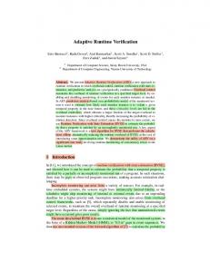
BACKGROUND & MOTIVATION Figure 2: Components composing a BBW system
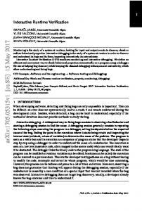
This work has been formulated in the scope of the the MBAT (Combined Model-based Analysis and Testing of Embedded Systems) European project [6] which consists of 38 project partners from 8 European countries (Austria, Denmark, Estonia, France, Germany, Italy, Sweden, UK). The main focus in MBAT is on the synergy between model-based analysis and testing, and the potentials that are provided by combining these two techniques in reducing the cost of verification and validation activities. Figure 1 shows an overall picture of this idea which we have discussed in more detail in [7].
not to be more than 200ms (in a sample implementation of the BBW system), or requirements on the periods of samplings done by sensors. Generally, BBW is an example of safety-critical, distributed and real-time systems in which meeting timing requirements has also direct impacts on the safety of the system.
2.1
Figure 1: MBAT approach: combining model-based analysis and testing One of the industrial use-cases in this project is the BrakeBy-Wire system (BBW) from Volvo. BBW is a braking system in which mechanical parts are replaced by electronic sensors and actuators and thus removing the hydraulic connections between the brake pedal and each wheel brake. Anti-lock Braking System (ABS) is usually an inherent functionality provided by BBW systems [8]. The purpose with the ABS subsystem is to prevent locking of the wheels by controlling braking based on calculated slip rate value. Slip rate is calculated according to the following formula (where r is the radius of the wheel):
A signal is essentially defined as a data structure. An example signal definition is shown in Figure 3. 1 2 3 4
s = (vehicleSpeed − wheelSpeed ∗ r)/vehicleSpeed If s is greater than a certain limit, then the brake actuator is released and no brake is applied, otherwise the requested brake torque is used. The Electronic Control Unit (ECU) for each wheel will have three application software components: one is a sensor to measure the wheel speed, one is an actuator for the brake, and the third one implements the ABS controller for the wheel. A schematic view of the BBW system components is shown in Figure 2 considering only one wheel for brevity. There are several timing requirements in BBW systems. For example, the total brake reaction delay could be specified
Extended Farkle
Farkle is a test execution environment that enables testing an embedded system in its target environment. It is originally developed for testing embedded systems built using OSE Real-Time Operating System (RTOS) [9]. OSE is a commercial and industrial RTOS developed specifically for fault-tolerant and distributed systems. LINX is the InterProcess Communication (IPC) protocol that is used in OSE. LINX provides the concept of direct and asynchronous message passing for communication and synchronization between tasks. This allows tasks to run on different processors or cores, while utilizing the same message-based communication model as on a single processor. This programming model has the advantage of not using shared memory. The messages that are passed between processes (i.e., tasks) are referred to as signals. The LINX protocol is also available for Linux, which is the operating system and platform used here to implement the system.
5
#define WHEEL_SPEED_SIG 1026 typedef struct WheelSpeedSignal{ SIGSELECT sigNo; float WheelSpeed; } WheelSpeedSignal;
Figure 3: Signal example Using the signal passing mechanisms of LINX, Farkle runs on a host machine and communicates with the target. Hence, Farkle enables testing an embedded system by providing certain inputs to the target in the form of signals and receiving the result as signals containing output values. The test scripts that are used to send and receive signals, and also determine the verdict of a test case (pass/fail) are implemented in Python. Moreover, in order for the signal passing mechanism to work between the host and target, the host
(i.e., the scripts run by Farkle on host) needs also to have information about signal structures. For this purpose, Farkle also generates signal definitions in Python from the signal definitions of the application source code, which is then imported and used in the Python test script. In our approach, Farkle serves basically as the test execution framework that we extended for this work with features to parse abstract test cases as input, and automatically generate executable test scripts from them, which are then run against the target.
1 2 3 4 5 6 8 9 10
Testing Methodology
State:(ABSFL.Entry) ABSFL.w=8 ABSFL.wheelABS=1 ABSFL.torqueABS=0 ABSFL.v=12 ABSFL.R=1/2
11 12
Transitions: ABSFL.Entry->ABSFL.CalcSlipRate { v> 0}
13 15 16
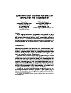
In [10] we have introduced a testing methodology to verify the runtime behavior of the BBW system against the desired behavior. In the approach, the architectural model of the BBW system is done in EAST-ADL modeling language [11], which is an Architecture Description Language (ADL) for automotive systems. The internal behavior of each component in the architecture is modeled using Timed Automata (TA) [12, 13] designed in Uppaal Port tool [14, 15]. A TA model describing the behavior of the ABS component of the BBW system is shown in Figure 4. Since in this work our focus is mainly on the functional behavior of the system, timing specifications are removed from the TA shown in the figure for brevity.
Transitions: ABSFL.idle->ABSFL.Entry { w:= 8, wheelABS:= 1, v:= 12}
7
14
2.2
State:(ABSFL.idle) ABSFL.w=0 ABSFL.wheelABS=0 ABSFL.torqueABS=0 ABSFL.v=0 ABSFL.R=1/2
State:(ABSFL.CalcSlipRate) ABSFL.w=8 ABSFL.wheelABS=1 ABSFL.torqueABS=0 ABSFL.v=12 ABSFL.R=1/2
17 18 19
Transitions: ABSFL.CalcSlipRate->ABSFL.Exit {vABSFL.idle { }
26 27 28 29
State:(ABSFL.idle) ABSFL.w=8 ABSFL.wheelABS=1 ABSFL.torqueABS=0 ABSFL.v=12 ABSFL.R=1/2
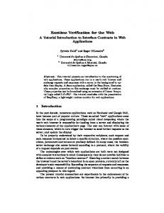
Figure 5: Trace information as Abstract Test Case
v==0 [torqueABS=0]
v0 [ ] v>=5*(v-w*R) [torqueABS=wheelABS]
CalcSlipRate
Figure 4: Timed automata model of the ABS component Different coverage criteria formalized as Timed Computational Tree Logic (TCTL) reachability properties, which actually represent requirements of the system, are applied in Uppaal Port which produces trace information as a result. As will be described in the next section, these traces serving as abstract test cases are then transformed into concrete ones which are essentially executable test scripts. By executing the concrete test cases, it is determined if the runtime behavior of the system differs from the desired behavior. In other words, it is checked that the order of system states at runtime matches what is specified in the models. Figure 5 shows a trace example generated from Uppaal Port. In [10], the overall testing methodology from EAST-ADL models down to concrete test cases and test results is described with different types of analysis and checks that can be done at the model level. In this paper, we start from the abstract test cases and provide an updated and complete implementation for the concrete test case generation part of that work, where it was presented as a draft idea how this generation (i.e., abstract to concrete) is feasible. By executing the concrete test cases, it becomes possible to determine if the state changes at runtime violate the order which is specified in the trace information and TA models,
and moreover, identify where along the transitions such a violation has happened. Also, since the main concern here is the states and transitions, we simply use the term state machine to refer to timed automata models in the BBW system, disregarding their timing specifications and additional semantics.
3.
EXECUTABLE TEST SCRIPTS
In this section, we describe how using Extended Farkle, concrete test cases (i.e., executable test scripts) can be generated from abstract test cases (i.e., the trace information generated based on Timed Automata models). To do so, the following steps are taken: 1. An abstract test case is read as input by Farkle. 2. The abstract test case is parsed and the order of states and transitions, along with the values of variables in each state, are identified. 3. Based on the information mentioned above, which is identified during the parsing step, a test script is created. The test script basically creates signals with values of variables at each state extracted by parsing the abstract test cases, which are then sent to the target system. 4. The initial values of variables that are sent to the target system by the test script, in the form of signals, trigger the SUT to execute and evolve through a set of states and transitions. 5. The information about the actual set of states and transitions taken by the SUT during execution is collected and sent back to the script (again in the form of signals).
6. The test script receives the result, that is, the information on the set of states and transitions, as well as the values of variables at each state. This information, collected during execution and at runtime, is then used to compare the actual order of states and transitions against the expected one originated from the models and specified in the abstract test-case.
1 2 3 4 5 6 7
void mbatAbs_calc(MbatAbsInput* input, void* hdl) { state = Idle; /* Internal variables of automaton */ float s; /* Output variables */ U32 TorqueABS = 0;
8 9
state = Entry;
10
7. If any discrepancy between the actual and expected orders of traversed states and transitions (with the option of also checking the expected values for variables) is found, the test result is evaluated to fail, otherwise a pass verdict is decided.
11 12 13 14 15 16 17 18 19
In the steps described above, the generation of executable test scripts is based on the following principles:
20 21 22 23 24
• For each variable (in the TA), we create an array containing all of their expected values at each state and in the exact same order as it appears in the abstract testcase as follows: = [x,..,y].
25 26 27 28 29 30 31 32
• The initial values of variables are used in the structure of a signal, which is then sent to the target.
33 34 35
• We define an additional array to preserve the order of states, in the form of: state = [x,..,y]; e.g., SM1 state = [1,2,4,5], where the numbers serve as IDs and represent a unique state in the automaton, respectively. • Based on the number of states, we create a loop in the script. • Inside the loop, we add assertion statements for each variable to check its expected value at the current state versus its received value at that state, which is retrieved from the log information sent back from the target (in the form of a signal). • An additional assertion statement is used in a similar way, for checking the actual order of visited states in the code versus the expected ones in the model.
Basically, this allows us to verify the internal state of the system, and to determine whether it is behaving as expected (as specified in the models) or not. Moreover, it makes possible to determine exactly between which states a deviation from the expected behavior has occurred. In other words, testers can get some ideas about the vicinity of a problem in the code, which can ease debugging and fixing that respective problem.
4.
APPLICATION OF THE METHOD
We have applied the method introduced in the previous sections to the ABS subsystem of the Brake-By-Wire system. To apply the method, there needs to be a way to track states at runtime. For this purpose, the implementation code of the ABS component is implemented in the form of a state machine and using a variable to keep track of different states, as shown in Figure 6.
while(state != Exit) { switch(state) { case Entry: { if(input->v > 0) {state = CalcSlipRate; } else if(input->v == 0) { TorqueABS = 0; state = Exit;} else { // Error } break; } case CalcSlipRate: { s = (float)(input->v - input->w*input->R)/input->v; if(s > 0.2) { TorqueABS = 0; } else { TorqueABS = input->WheelABS; } state = Exit; break; } case Exit: { break; } } printf(" Tracing ABS calculation state:%d\n", state); mbatAbs_transition(state, input->w, input->WheelABS, input->v, TorqueABS, input->R, (MBAT_TRC*)hdl); state = Idle; } }
Figure 6: Implementation of the ABS component
To generate an executable test script from trace information, the steps mentioned in Section 3 are taken. Figure 7 shows the test script that is generated for the abstract test case shown in Figure 5. This script is then executed by Farkle on the host system which in turn communicates with the target using signals. As can be seen in Figure 7, at lines 7-11 the values of variables, which are defined as part of the input signal to be sent to the ABS subsystem, are set. Sending of the signal is then done at line 12 using the send API of the LINX protocol. Upon the receipt of the signal on the target, the variable values are extracted from the signal and used to perform different calculations as done in the code part depicted in Figure 6. While the calculations are performed on the target, each state change is logged along with the values of variables at each state. This log information is then sent back to the test script on the host again using signal passing mechanism. The script loops through each log record (contained in the signal) and compares the actual order of states and values of variables collected from the target against the expected ones. The expected values are included in the test script during the generation process of the executable test script as shown at lines 15-20 in Figure 7. This way it is determined whether the actual execution of the system in terms of states and transitions follows the expected behavior as described by state machine models or not. Part of the information that is produced as test result is shown in Figure 8. Besides getting a pass or fail result about whether the be-
1 2 3 4
import sys import signals import xmlrunner ...
5 6 7 8 9 10 11 12
# Sending input signal to ABSFL sig_send_ABSFL = signals.ABSFL_INPUT_SIG() sig_send_ABSFL.input.ABSFL_w = 8 sig_send_ABSFL.input.ABSFL_v = 12 sig_send_ABSFL.input.ABSFL_wheelABS = 1 sig_send_ABSFL.input.ABSFL_R = 0.5 self.linx.send(sig_send_ABSFL, self.pid_ABSFL)
13 14 15 16 17 18 19 20
# Expected values ABSFL_w = [8, 8, 8] ABSFL_wheelABS = [1, 1, 1] ABSFL_torqueABS = [0, 0, 0] ABSFL_v = [12, 12, 12] ABSFL_R = [0.5, 0.5, 0.5] ABSFL_state = [1, 2, 3]
21 22 23 24
# Receive signals from test targets sig_recv_ABSFL = self.linx.receive( [signals.ABSFL_OUTPUT.SIGNO])
25 26 27 28 29 30 31 32 33 34 35 36 37 38 39 40 41 42 43
# Testing of ABSFL for i in range(sig_recv_ABSFL.num_states): print "Transition %d:" %(i+1) self.assertEqual( sig_recv_ABSFL.states[i].state, ABSFL_state[i]) print " state = %d" %sig_recv_ABSFL.states[i].state self.assertEqual(sig_recv_ABSFL.states[i].w, ABSFL_w[i]) print " w = %d" %sig_recv_ABSFL.states[i].w self.assertEqual( sig_recv_ABSFL.states[i].wABS, ABSFL_wABS[i]) print " wheelABS = %d" %sig_recv_ABSFL.states[i].wheelABS self.assertEqual( sig_recv_ABSFL.states[i].tABS, ABSFL_tABS[i]) print " torqueABS = %d" %sig_recv_ABSFL.states[i].torqueABS self.assertEqual(sig_recv_ABSFL.states[i].v, ABSFL_v[i]) print " v = %d" %sig_recv_ABSFL.states[i].v self.assertEqual(sig_recv_ABSFL.states[i].R, ABSFL_R[i]) print " R = %d" %sig_recv_ABSFL.states[i].R
44 45 46 47 48 49
if __name__ == ’__main__’: del sys.argv[1:] unittest.main(testRunner=xmlrunner.XMLTestRunner( output="test")) ...
Figure 7: Generated Python script 1 2 3 4 5 6 7 8 9 10 11 12 13 14 15 16 17 18
Failure=0, Time=3.464 -----------------------Transition 1: state = 1 w = 8 wheelABS = 1 torqueABS = 0 v = 12 R = 0.5 Transition 2: state = 2 w = 8 wheelABS = 1 torqueABS = 0 v = 12 R = 0.5 ... ------------------------
Figure 8: Test result
havior of the system conforms to the models, in case of failure, it is also possible to identify between which two states
a deviation from the expected behavior has occurred. This way, the suggested method also helps with the localization of defects and provides hints to testers about which parts in the system might contain errors and need to be investigated. For example, in case of the trace information in Figure 5 and considering the specified input values, the expected behavior of the system in terms of state changes should be (ignoring the Idle state): Entry → CalcSlipRate → Exit. If for any reason, the actual runtime behavior of the system is observed to be Entry → Exit, for instance, it shows that there is a problem in transiting from Entry state to the CalcSlipRate state. Similarly Entry → CalcSlipRate → CalcSlipRate → Exit as the observed behavior will not be the desired behavior. One of the actions that can be taken in such cases is to generate more traces and create more test cases targeting those states and paths that are identified as violating the model, to further help with pinpointing the root cause of the problem. Additionally, more analysis (model-based analysis) can be performed targeting the part of the model whose representative test case has failed. This also further emphasizes the potentials of combining modelbased analysis and testing, and exploiting the synergy between the two; as is aimed for in the MBAT project.
5.
RELATED WORK
Uppaal is a tool suite for modeling and verification of realtime systems modeled as networks of timed automata [15]. Three main parts that constitute Uppaal are a description language, a simulator and a model-checker. Uppaal is an example of prominent tools and methods for verification of real-time systems at the modeling level. It does not, however, concern implementation code and actual execution of the system. Uppaal Port is one edition from the family of Uppaal tools which applies the Partial Order Reduction Technique (PORT). It is mainly intended for modeling, simulation and verification of component-based systems in real-time embedded domain. Uppaal TRON [16,17] is a testing tool based on the Uppaal engine that is designed for black-box conformance testing of real-time systems. Uppaal TRON derives, executes, and evaluates test cases against the implementation of the system in real-time. However, the main difference between the testing method of Uppaal TRON and our approach is that Uppaal TRON addresses online generation and execution of test cases based on the results of previous executed test cases, and focuses mainly on observable input and output actions, considering the Implementation Under Test (IUT) as black-box and assuming that its internal states are not observable [17]. While in our approach, test cases are only generated offline, and also the IUT is considered as white-box whose internal state changes are fully tracked and compared against the TA models. Tracking of state changes at runtime is thus needed and introduced to enable this feature. Also what is tested in our approach is not the output from the IUT, but the order of states and the values of relevant variables at each state. In [18], we have provided a method similar to the one we described here in this work, but with the focus on testing timing properties and constraints against timed automata models. In contrast, our main concern here in this paper has been on the functional aspects of the system than extrafunctional properties such as timing. As for localization of faults and defects, [19] and [20] provide surveys on different
localization methods. J.A Jones and M.J. Harrold in [21] offer an empirical evaluation of four automatic fault localization techniques, namely Set union, Set intersection, Nearest Neighbor, and Cause Transitions, compared with Tarantula which is another well-known fault localization method. These methods, however, mainly focus on the statements and at the code level, while our method enables localization of defects at the model level and the counterparts at the code, provided that the code is implemented in the form of a state machine. SOBER [22] is a statistical model-based bug localization approach which models evaluation patterns of predicates. It measures the bug-relevance of program predicates by applying probabilistic and quantification principles on them. Ning Ge et al. in [23] propose a model-based diagnosis approach based on Hidden Markov Model (HMM) for fault localization in integration testing. They perform analysis on different components in the system and map each to an HMM, and then calculate fault probability for the components. Abstract State Machine Language (AsmL) is a formal software specification language based on abstract state machines [24]. It aims to provide a human-readable, machine-executable, complete yet minimal abstraction model of a system’s operations. AsmL could serve as a way to represent state machine model of the use-case described in this work. However, for the use-case, Timed Automata formalism was considered for modeling the system as it can capture timing aspects and enables performing different types of analysis using Uppaal. Moreover, a C/C++ code implementation of the states and transitions in the models was considered since it is deemed as the suitable language for the embedded needs of the usecase.
6.
DISCUSSION AND CONCLUSION
In this paper, we introduced a method for testing the behavior of a system in term of its internal states and transitions. Such testing is needed in order to make sure that the systems behaves as expected; where the expected behavior is captured as part of the architectural models. This is especially important considering that models are used as the source of information for performing model-based analysis; and therefore, any deviation from the models can mean the invalidation of the analysis results. For this purpose, our method is helpful in order to check if the actual runtime behavior conforms to the models. It is important here to note that as a fundamental rule in testing, passing of test cases does not necessarily mean the absence of errors and it just helps to increase our confidence in the correctness and quality of the software product. Moreover, our method enables to see precisely on the transition between which states a deviation from the expected behavior has occurred. This way, it offers a form of defect localization feature which helps to understand where the root cause of a problem could be and provides hints and information about the vicinity of a problem in the system. In summary, the approach contributes to identifying inconsistencies between design models of a system and its actual behavior at runtime. Currently, we are extending the approach to include traces that cover several components in the architectural model. This way, it becomes possible to also examine the communication paths across interacting components and test their be-
haviors in terms of communication. Such an extension would also be helpful in comparing different architectural models of a system with respect to the behavior of their components; for example, to test if they result in the same communication order and pattern at runtime or not. This can especially be interesting in the evolution of a software system where architectural models and components are refactored, components are replaced with a different version or new ones are added, and so on [25]. Careful investigation of such features and scenarios are left as a future work. Another direction of this work would be strengthening the combination of model-based analysis and testing in our method by establishing a more explicit feedback loop between the test results and the models. One of the scenarios that will become possible using such a loop and relationship is that whenever a failure is detected by testing states and transitions at runtime, that path at the model could be marked and highlighted. More (static) analysis can then be performed on that part of the model to see if the problem can be identified and solved statically; otherwise, more test cases can be generated for that part to further examine it dynamically. Moreover, automating the generation of abstract test cases covering the path in which a failure is observed may also be done; leading to an automated complete chain considering that the generation of concrete test cases from abstract ones is already automated as described in this work. This helps to create and execute more test cases to further scrutinize the execution path that deviates from the expected behavior. These possibilities and related issues such as consideration of appropriate test termination criteria in such automated testing tool chains need to be further examined. In this paper, we did not deal explicitly with if the code is generated from models (entirely or partially) or manually developed. In either case, our approach helps to gain more confidence that the behavior of the system when the code is executed matches the expected behavior captured by models. On the other hand, the closer the code is to the models (e.g. through an automatic and verified code generation process), the less might be the deviation of system’s runtime behavior from the models. This, of course, needs to be further investigated and verified. The main point to note though is that no matter how much analysis is performed on the models, if the assumptions that are taken into account for those analyses are violated at runtime, their results may not be valid anymore. Moreover, situations may still occur at runtime that might have been neglected during system design or are hard to predict which can thus lead to the deviation of a system’s actual behavior from its desired one. Considering the case that the models of a system are reverseengineered and constructed from code (e.g. in a legacy system), again the proposed approach can be useful towards verifying the intended and actual behavior of the system. In such a scenario though, the result of the approach could imply if the reverse-engineering process was successful or not and if models which are supposed to capture the system behavior correctly have been successfully constructed. The defect localization feature that is provided in our method is somewhat simpler and different from major bug/fault/de-
fect localization techniques in the literature which are based on formal methods, clustering, and probabilistic and statistical methods. However, it provides hints at the model level based on the test results, which has been the main purpose of it. Applying these techniques and methods to complement the defect localization feature introduced in this paper can also be another interesting future extension.
7.
ACKNOWLEDGMENTS
This work has been supported by the MBAT European Project [6] and Alten AB (formerly Enea Services Stockholm AB) [26] through the ITS-EASY industrial research school [27]. The research leading to these results has received funding from the ARTEMIS Joint Undertaking under grant agreement no 269335 (see Article II.9. of the JU Grant Agreement) and from the Swedish Governmental Agency for Innovation Systems (VINNOVA) [28]. We would also like to thank Raluca Marinescu and Dr. Cristina Seceleanu at M¨ alardalen University for their technical tips and support for this work.
8.
[10]
[11]
[12]
[13]
REFERENCES
[1] M. Utting and B. Legeard, Practical Model-Based Testing: A Tools Approach. San Francisco, CA, USA: Morgan Kaufmann Publishers Inc., 2007. [2] J. Zander, I. Schieferdecker, and P. Mosterman, Model-Based Testing for Embedded Systems, ser. Computational Analysis, Synthesis, and Design of Dynamic Systems. Taylor & Francis, 2011. [Online]. Available: http://books.google.se/books?id=fzgzNW alD0C [3] M. Saadatmand, A. Cicchetti, and M. Sj¨ odin, “Design of adaptive security mechanisms for real-time embedded systems,” in Procs of ESSoS’12. Springer-Verlag, 2012, pp. 121–134. [4] M. Utting, A. Pretschner, and B. Legeard, “A taxonomy of model-based testing approaches,” Journal of Software Testing, Verification and Reliability, vol. 22, no. 5, pp. 297–312, 2012. [5] J. Peleska, “Industrial-strength model-based testing state of the art and current challenges,” in Proceedings of the Eighth Workshop on Model-Based Testing, March 2013, pp. 3–28. [6] MBAT Project: Combined Model-based Analysis and Testing of Embedded Systems, http://www.mbat-artemis.eu/home/, Accessed: November 2013. [7] M. Saadatmand and M. Sj¨ odin, “On combining model-based analysis and testing,” in Tenth International Conference on Information Technology: New Generations (ITNG), Las Vegas, NV, USA, 2013, pp. 260–266. [8] S. Anwar, “An anti-lock braking control system for a hybrid electromagnetic/electrohydraulic brake-by-wire system,” in American Control Conference, 2004. Proceedings of the 2004, vol. 3, 2004, pp. 2699–2704 vol.3. [9] Enea, “The Architectural Advantages of Enea OSE in
[14]
[15]
[16]
[17]
[18]
[19]
[20]
[21]
Telecom Applications,” http://www.enea.com/software/solutions/rtos/, Last Accessed: November 2013. R. Marinescu, M. Saadatmand, A. Bucaioni, C. Seceleanu, and P. Pettersson, “East-adl tailored testing: From system models to executable test cases,” M¨ alardalen University, Technical Report ISSN 1404-3041 ISRN MDH-MRTC-278/2013-1-SE, August 2013. [Online]. Available: http://www.mrtc.mdh.se/ index.php?choice=publications&id=3373 “EAST-ADL,” http://www.east-adl.info/Specification.html, Last Accessed: November 2013. R. Alur and D. L. Dill, “A theory of timed automata,” Theoretical Computer Science, vol. 126, no. 2, pp. 183 – 235, 1994. J. Bengtsson and W. Yi, “Timed automata: Semantics, algorithms and tools,” in In Lecture Notes on Concurrency and Petri Nets, ser. Lecture Notes in Computer Science vol 3098, W. Reisig and G. Rozenberg, Eds. Springer–Verlag, 2004. J. H˚ akansson, J. Carlson, A. Monot, P. Pettersson, and D. Slutej, “Component-based design and analysis of embedded systems with uppaal port,” in Automated Technology for Verification and Analysis. Springer, 2008, pp. 252–257. G. Behrmann, R. David, and K. G. Larsen, “A tutorial on Uppaal 4.0,” http://www.it.uu.se/research/group/ darts/papers/texts/new-tutorial.pdf, November 2006. Uppaal for Testing Real-Time Systems Online (TRON), http://people.cs.aau.dk/˜marius/tron/, Accessed: November 2013. K. G. Larsen, M. Mikucionis, B. Nielsen, and A. Skou, “Testing real-time embedded software using uppaal-tron: an industrial case study,” in Proceedings of the 5th ACM international conference on Embedded software, ser. EMSOFT ’05. New York, NY, USA: ACM, 2005, pp. 299–306. M. Saadatmand and M. Sj¨ odin, “Testing of timing properties in real-time systems: Verifying clock constraints,” in 20th Asia-Pacific Software Engineering Conference (APSEC), Bangkok, Thailand, December 2013. W. Eric Wong and Vidroha Debroy, “A survey of software fault localization,” Technical Report UTDCS-45-09, The University of Texas at Dallas, November 2009. M. A. Alipour, “Automated fault localization techniques; a survey,” Technical report, Oregon State University, 2012. J. A. Jones and M. J. Harrold, “Empirical evaluation of the tarantula automatic fault-localization technique,” in Proceedings of the 20th IEEE/ACM International Conference on Automated Software Engineering, ser. ASE ’05. New York, NY, USA: ACM, 2005, pp. 273–282.
[22] C. Liu, X. Yan, L. Fei, J. Han, and S. P. Midkiff, “Sober: Statistical model-based bug localization,” SIGSOFT Softw. Eng. Notes, vol. 30, no. 5, pp. 286–295, Sep. 2005. [23] N. Ge, S. Nakajima, and M. Pantel, “Hidden markov model based automated fault localization for integration testing,” in Software Engineering and Service Science (ICSESS), 2013 4th IEEE International Conference on, 2013, pp. 184–187. [24] M. Research, “Abstract state machine language (asml),” http://research.microsoft.com/en-us/projects/asml/, Accessed: January 2014. [25] H. Pei-Breivold, I. Crnkovic, and M. Larsson, “A
systematic review of software architecture evolution research,” Journal of Information and Software Technology, July 2011. [26] Alten/Xdin AB, http://www.alten.se/en/om-alten/nyheter/ the-acquisition-of-enea-experts-is-now-complete/, Accessed: January 2014. [27] ITS-EASY post graduate industrial research school for embedded software and systems, http://www.mrtc.mdh.se/projects/itseasy/, Accessed: November 2013. [28] VINNOVA: Swedish Governmental Agency for Innovation Systems, http://www.vinnova.se/en/, Accessed: November 2013.