SAS architecture: Verification Oriented Formal Modeling of Concrete Critical Systems* Valine Roy Centre de MathCmatiques AppliquCes Ecole des Mines de Pans, France
[email protected]
Annie Ressouche JNFUA Orion Project Sophia Antipolis, France
[email protected] Jean-Yves Tigli 13s Laboratory CNRS UMR 6070 University of Nice Sophia Antipolis, France
[email protected]
Daniel Cheung ESSI University of Nice Sophia Antipolis, France
[email protected]
Abstract - Concrere critical systems validation is a major challenge in any development process. Model checking verification offers exhaustive and automated validation. To apply this methodology, rhe specification of critical systems musr be supported by a formal mathematical well-sounded model. To this end, we rely on syuchronoiis language to model such systems and to ensure model existence we consider systems f a / h g info a particular SAS architecrure. SAS sysrems are composed by a synchronous main controller that manages autonomic asynchmnous tasks. Abstraction methods provide us with the required synchronous model. We show how our approach suits wearable computer applications designing and how the modeling we propose meets the requirements of wearable computer validation.
(Signal [ 7 ] )are all compiled into finite-state machines and therefore offer a suitable framework for applying modelchecking techniques. We show how the Esterel language is well suited for specifying the control parts of critical systems and provides us with the required characteristics : it is reactive and the synchrony hypothesis ensures us that it is deterministic (same reaction to similar entries). Its design offers appealing operators to express reactivity (wait and emit events, preemption, powerful exception mechanism,etc.). Moreover, it allows us to decompose a synchronous specification into several communicating entities, each of them dedicated to a specific purpose. Then we show how model-checking is suitable for critical system validation.
Keywords: Model Checking, Finite-State Machine, Synchronous Asynchronous Approach, Wearable Computer
Any realistic application accepts different levels of description involving entities of various kind which will be modeled differently : some via a controller (synchronous), some via a model specific to their sequential activity (asynchronous). But in such a setting, model-checking cannot help to verify whole general critical systems. To over pass this drawback, we propose the definition of synchronous/asynchronous(S~s) architecture enabling a global modeling of the system for verification purposes. Our architecture tends to set aside and regroup the interactions between asynchronous components. Indeed, these interactions are very often at the source of the systems complexity and difficulties in their modeling. It encompasses three levels: decisional, behavioral and functional. At the behavioral level we find asynchronous, autonomous, concurrent and non interacting components. Each of these components presents a collection of activities which can be dynamically reconfigured. The modeling methods for the asynchronous components will hinge on how critical their role is within the whole system. Critical components will be modeled in our synchronous formalism by presenting their behavior as an
1 Introduction The problem we address in this paper concerns the field of verification oriented formal modeling of concrete critical systems (whether this critical aspect arises from the functional, real time, resource availability or context of use sides of the problem). The specification of such systems must be supported by formal, mathematically-founded methods in order to be satisfactory and reliable. Model-checking verification offers exhaustive and automated verification methods [6]. It requires describing the systems behavior as finitestate machines. Reactive languages are intended for a natural and reusable description of reactive systems (i.e., which are perma nently reacting to their environment). These languages, be they declarative, data flow oriented (Lusrre [ 7 ] ) ,imperative. control dominated (Esterel [Z]) or declarative, multi-clock -0-7803-79sz.7mm7.00
0 2003 IEEE.
181
__
. -. :
Authorized licensed use limited to: UR Sophia Antipolis. Downloaded on December 8, 2009 at 13:54 from IEEE Xplore. Restrictions apply.
abstraction of reality, thus enabling formal verification tools to be applied. The real implementation of these components will have to satisfy the constraints resulting from the venfication of their model. The decisional level consists in a collection of synchronous controllers managing the activities of the asynchronous components and their reconfiguration. Each synchronous controller is individually validated and the validation of the global system rests on a modularity characteristic of model-checking (known as assumeguarantee paradigm [6]).The functional level is made up of dedicated components (hardware or software), the interface of which only is significant. The paper is organized as follows. The next section introduces the formal model we consider to verify S A S systems. In section 3 we define the SAS architecture. In Section 4, we apply S A S architecture specification to wearable computer applications. We show how wearable computer field fits the S A S architecture, and how this architecture meets the requirements of such applications through a dedicated dive computer cxample. Finally, in section 5, we discuss some related works and future ones and conclude.
2 Formal Modeling and verification In order to apply formal verification techniques on system, its specification must be supported by mathematicallyfounded methods that allows representing its behavior as a finite-state machine. The section 2.1 describes the requirements that this formal modeling impose to language design and how the reactive languages fulfill to these requirements through some precise hypothesis. The section 2.2 shows how reactive languages are a suitable framework for applying model-checking techniques.
2.1 The Synchronous Model Synchronous languages are devoted to a natural and reusable description of reactive systems (i.e., which are permanently reacting to environment stimuli). They appear to he robust and expressive, high-level mathematical formalisms to specify reactive parts of critical systems. In the aim to increase system reliability, it becomes now necessary to use, every where it applies, methods ensuring their safety. Verifying system properties implies naturally to be able to exhibit all the system possible behaviors. That is the framework offered by reactive synchronous languages : a reactive program will he compiled in the mathematical model of finite automata that allows the use of exhaustive verification techniques.
2.1.1 The Synchronous Hypothesis As already mentioned, reactive systems are always ready to react to extemal stimuli. The reaction rhythm is environment driven and the system must work accurately at the environment speed. When giving to a system twice the same entry sequence, it must always react the same way and cause the same output sequences, this is needed to ensure determinism. As system becomes complex, its size increased
and system description needs expressivity facilities like hierarchy and modularity. A system is naturally expressed as concurrent communicating subsystems, each one assuming a part of the global specifications. Verification techniques, like model-checking, apply to the formal model of finite automata. In the aim to apply these techniques on our system, we require compiling it in this formal sequential model. In order to conciliate these requirements (reactivity, determinism, modularity, finite-state machine compilation model), the synchronous approach do hypotheses. Communications, between system and environment and between subsystems, are non-blocking communications done by instantaneous broadcast of events. This ensure that every subsystems have a coherent view of event status. Let us call the following sequence a reaction : entries are given to the system, it is activated, it reacts, it produces outputs and it becomes again ready to react. The sequence of system reactions describes a logical time and induces the notion of instant. We can then speak about the system logical clock. Input events cannot arrive and being taken into account as the system is currently proceeding to a reaction : this is the hypothesis of atomicity. Through this hypothesis, input and output events of a single reaction are considered as being synchronous, reaction duration is considered to be zero and event emission and reception are considered as being simultaneous.
2.1.2 The Synchronous Languages The classical reactive synchronous languages are : the imperative language Esterell21 dedicated to program controldominated systems; the declarative language Lustre[7] suitable to program data-flow oriented systems; the declarative language Signal[7] helpful to program systems requiring multi-clock description; the graphic language SyncCha~ts[l] based upon the Esterel semantics; the mode automata one[ 101useful when systems behavior is compound of different modes related by transitions between them. The choice among these languages mainly depends on application types. The imperative synchronous model (Esterel like) seems very convenient to express the control dominated parts of critical systems. In this model, the parallelism is a purely logical operator that has been introduced in the language only for the sake of expressivity. It simplifies the action of programming by allowing the code to be structured in a very natural way. The code evolve's more easily and validated subsystems can be reused in different setting. Signal is the single mean to achieve communication between subprogramsor with the environment. The language operators express constructions like concurrency of statements, sequence of statements, signal emission and expectation, test of signal presence, mechanisms of exception, weak and strong abortion, non-recursive sub modules calls, ... This synchronous model allows instantaneous reaction to signal presence and to signal absence. The instantaneous reaction to signal absence guaranties the atomicity paradigm. As a consequence, a program can react instantaneously to a signal absence by emitting it, 182
Authorized licensed use limited to: UR Sophia Antipolis. Downloaded on December 8, 2009 at 13:54 from IEEE Xplore. Restrictions apply.
that leads clearly to inconsistency. Since the compilation relies on a well-sounded mathematical semantics, this induces the compilation of some programs to he impossible to establish due to causality cycles between signals. When compilation succeeds, the compiled code is sequential and could he represented as well as by finite automata than net lists. This compilation model is very interesting : it allows the use of formal verification of programs by model-checking.
2.2 Critical Systems Validation Several approaches address system validation : testing, simulation, theorem provers and model checking techniques. The most widely used verification technique are extensive testing and simulation. They offer a first level of validation and are useful methods to detect errors. Nevertheless, they are not exhaustive and can miss significant errors in large designs even if formal methods offer automatic tests generation and improve their coverage. Although there has been considerable research on the use of theorem provers, this technique is time-consuming and often require a great deal of manual intervention. Existing tools in this field are proof-checkers and the proof is built by the user. Model checking is an alternative verification technique exhaustive and automatic. Typically, the user provides a model of its application and the specification to he checked. The model checking algorithm will either answer true to indicate that the model satisfies the specification or give a counterexample execution showing why the specification is false.
2.2.1 Model Checking Model checking practice encompasses three main activities: first modeling the design into a given formalism, second express the property to be checked and finally interpret the result given by the model checking algorithm. The most popular model used by model checkers is simple automata or communicating networks of automata. Such a model is well suited to describe the set of all the executions of a system. To get the model of a design, synchronous languages [7]can he used and their compilation automatically gives the model. Temporal logic is a dedicated language to express the properties we want to check. With such a logic, we can formalize properties about the executions of a system; an execution being a sequence of reachable states of an automata. A property is expressed from input and output events of the system (for instance: start and stop signals, alarm, speed, ...) or a boolean combination of these. Temporal operators allow to speak about the ordering of events in time without introducing time explicitly (for instance: “the next state satisfy property p”, there is a future state where property q holds,..). In addition, quantifiers express properties for all the executions (universal quantifier) or for an execution at least (existential quantifier). The major drawback of model checking approach is the sheer size of the models to he handled. However, the emergence of symbolic model-checking (implicit model representation)[6] and the reliance on SAT methods[3] (pro-
cedures for deciding whether propositional logic formulae are satisfied) guarantee scaling up model-checking scoping. Hence, in new model checker as NuSMV [ 5 ] , an efficient SAT-solver algorithm complement the symbolic approach.
Model Checking Issues In model checking activity, it could be difficult to build the target model. On one hand, we have to face the state explosion problem. On the other hand, the design can involve some components not straightly expressible in an automata network setting as real type variables. Nevertheless, powerful techniques have heen investigate to get automata model checker can deal with. Useful ones are the absrracrion both on data and control[6] and the observer automata method[91. The absrracrion method results in smaller automata preserving temporal logic formulae. Several techniques are : the abstraction over the control which consists in partitioning the state space to get a smaller automata. At the opposite, the abstraction over data which consists to simplify the range of the variables (from infinite types to finite ones). We use these abstraction methods to model our S A S architecture. The data and the asynchronous tasks of our designs have possibly infinite domains. Only an abstraction over data will allow to express property concerning variables. Particularly, infinite type variable domains will be partitioned into a finite number of relevant sub domains. The observer automata method consists in listening non intrusively only the executions we are interesting in. The reachability of a state of the model consisting in the parallel operation between the observer and the design model give us some informations about an expected behavior. This powerful technique is quite natural since it allows to express the property in the same language than the design we want to check. 2.2.2
3 Synchronous I Asynchronous Architecture Any realistic application holds several levels of description, that involve miscellaneous entities of different nature and that require different models : some will he modeled by a controller (synchronous), some others by different sequential behaviors (asynchronous). We define an architecture (SAS ) dedicated to systems where synchronous and asynchronous components need to coexist, so as to allow the modeling and verification of the global system. Most of the component-oriented software environments allow a developer to program the final application in the classical four-steps process : I) assembling hardware components; 2) designing applicative (know-how) software components; 3) configuring and assembling all the software components; 4) writing a minimal invocation software for the application. This approach provides for basic components reusability, and turns out to be satisfying for developing simple applications made of chained functional components. This methodology leads to a two-level software architecture : an - often
183
Authorized licensed use limited to: UR Sophia Antipolis. Downloaded on December 8, 2009 at 13:54 from IEEE Xplore. Restrictions apply.
implicit - applicative scheme for an assembly of functional components. This applicative scheme consists in a set of data communications between components and the control of each component for the overall application coherence (the real decisional part of the application). When facing the need for developing more and more elaborated, complete and flexible applications, the complexity of software development and design becomes problematic. by making validation very difficult and preventing from any formal verification.
1
DecisionalComponent
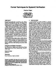
3.1 Behavioral and Functional Levels A Behavioral Component is a domain specific component or assembly of functional components that is strongly connected to the physical inputs and outputs of the system. In fact, a behavioral component is a chain of execution we do not interact with other behavioral components. This solution prevents new functionalities to alter the execution of the system. Thus behavioral component are independent entities of the critical system. Each behavioral component is likely to exhibit a set of activities, each corresponding to a thread or task, exclusive with each other within a given behavioral component, and propagating a control flow to its interconnected functional components. Let us note that, for each behavioral component, a " N A C (no activity) activity allows to freeze the component. Behavioral components are autonomous in that they do not interact directly with each other. This allows selecting any activity for each behavioral component without having to worry about any possible dependency between those components, as opposed to more classical approaches(see figure 2). The interactions that would though be necessary, such as access conflicts to resources of the critical system, are then deferred and managed by the decisional level.
Figure 1: SAS architecture
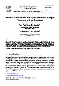
In order to reduce that complexity we propose the S A S architecture, that in much the same way as above, will allow us to manage software developments and to take advantage of formal verification tools. We have a three-levels decomposition (see figure I). It has the additional advantage to introduce a synchronous decisional level that allows to : simultaneously manage several behavioral components (that are asynchronous tasks) developed independently of each other, and thus to make them reusable; e
adapt these vely behavioral components to the application's context volatility, by managing their activities; offer a formal framework that supports formal verification by model checking.
SAS architecture has three levels : decisional, behavioral and functional. A new intermediary level, called behavioral level, is made of asynchronous, autonomous, concurrent and independent components. They all provide a set of dynamically reconfigurable activities. The modeling techniques of the asynchronous components will depend on the criticity of their respective role in the global system. The decisional level is a set of synchronous controllers that manage the activities and the reconfiguration of the asynchronous components. Each synchronous controller i s separately validated, and the global system validation relies on the assumeguarantee property. The functional level is achieved through dedicated components.
Figure 2: Behavioral Component Communication We will deal separately with the special case of the critical behavioral components. Actually, precisely because they are critical, some components will be modeled in our synchronous formalism by representing their behavior as an abstraction of the real life, thus enabling formal verification. Our synchronous model, given its operators assumeguarantee property (compositionality), will allow us to check some properties in the global system. The actual implementation of these components will then of course need to comply with the constraints resulting from their ideal model's verification, and will often be developed a posteriori. On the other hand, the non-critical behavioral components will most of the time encapsulate some existing applicative scheme and functional components. They will appear in the architecture as a piloting interface of their activities. The functional level is achieved through hardware and software dedicated functional components, whose only the interface is meaningful. The set of functional components remains to be designed (implemented or chosen into libraries), assembled and tested by the application developer. Functional components are the application lowest-level components.
Authorized licensed use limited to: UR Sophia Antipolis. Downloaded on December 8, 2009 at 13:54 from IEEE Xplore. Restrictions apply.
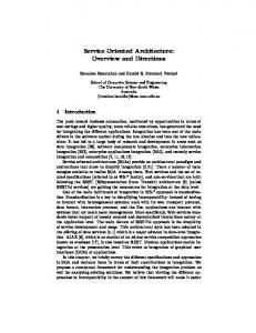
3.2 Decision Level The decisional level is intended to deal with the global activity of the system. It is the central part of the complex critical systems we are designing. It is made of two parts : the abstract model of its environment and the decision process himself. This process takes advantage of the previously described works on the imperative-synchronous reactive model allowing for assume-guarantee properties and formal verification by model-checking. The abstract model of the decisional level environment is made of two separate sets : input data and output data. We will see that these data do not need the same processing. The abstract model of the data describes the environment context. We consider as input, any data that represents the state of the global system : both the environment and the driven system. We represent the set of all possible input data as the following Cartesian product : I = WOx ._.x W,, where W, are the definition sets of the different input data. Nevertheless, it is interesting and necessary for formal modeling issue, to reduce the number of the possible states of such a structure. Hence, we avoid to take into account the large number of all the data possible values but consider only a more restricted number of values corresponding to a meaningful evaluation of these values. In our architecture a set of preprocessing reduces the input data cardinality. Finally the data w, can then be represented by a variable with n(i) possible states. The induced events correspond to data modifications. The definition set of the input-data abstract model (see figure 3), is the Cartesian product: I = [l..n(O)] x ... x [l..n(l)]. The abstract model of the output data represents the activity of the system i.e. the current activities of all the behavioral components. Each component i has a set of activity {at, ...,a y “ ’ } . a: being the j C h activity of the ith component. The Cartesian product (see figure 3) 0 = [l..m(l)] x _._x [I..m(p)] is the finite structure of all the system output data. The reduction of the output-data number of values, contrary to the input data, is not a significant problem here, because the number of the activities of a component is in general very limited. A component is attributed at Ieast two activities “component active” (AC) and “ c o m p nent inactive’’ (NAC) and can possess one be two additional activities.
E$#++
Uipr M. .be”*
-1
4.1 Examole: a Dive Comouter
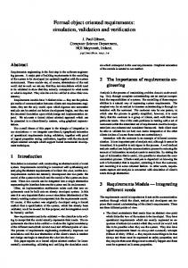
Figure 4: WComp embedding of dive computer implementation
A dive computer is an embedded system dedicated to assist a diver during his activity. The dive computer has different functions. It computes and displays all the information needed during a dive :the diver physical’s state (air consumption, heart pulsing; tissue gas rate, ...) and the dive important values (battery voltage, depth, pressure,..). It helps the diver during the nominal phases of his dive :decompression ceiling management (ceiling duration and depth holding). It detects the problems, alerts the diver, suggests him a behavior to follow and keeps on assisting him until he gets out of water. For instance, in case of an air consumption problem, the computer will propose an emergency lift back without ceiling, control the lift hack and, once the diver out of water, advise for a stay in a decompression box. The computer must warn the diver when his dives are too close one from each other or when the diver intends to take the plane too shortly after a dive. This application is specified as a SAS design and implemented using WCOMP software environment : a Rapid Application Development Toolkit for Wearable Computer based on Java [41; synchronous parts being embedded inside java components(see figure 4).
o- h
*rm .t.e
-rc-
Figure 3: Data abstract modeling
4
‘‘wearable computer” system is a multi usage system working in any environment for mobile user. This term does not gather only applications related to “communicating clothes” or “cognitive clothes” but it concerns also critical embedded applications dedicated to mobile user help (dive computer, medical computer,..). We illustrate our purpose on a specific wearable computer: a dive coinpurer application. We intend to show that the SAS architecture fits wearable-computer application design and we discuss the benefit brought by specifying applications in such a way.
Using SAS Architecture for Critical Systems
We apply our approach to specific critical systems known as “wearable computer” systems. As already mentioned, a
185
Authorized licensed use limited to: UR Sophia Antipolis. Downloaded on December 8, 2009 at 13:54 from IEEE Xplore. Restrictions apply.
The decisional component is a synchronous supervisor that listens to an abstract version of the dive-computer input data and manages the underlying behavioral components. The dive-computer input-data come from several sensors weared by the diver : the ascent rate, the pressure, the depth, the date, the tank pressure, the breathing rate, the heart rate, the air consumption, the battery status. To obtain the inputdata abstract model, pre processing perform an abstraction of the input data : from a given physical model of the diver, we compute the required ceilings and their respective duration; from the diver's air consumption and his tank pressure, we evaluate the dive time remaining. The input-data abstract model is the set of the possibly valued input signals, the synchronous supervisor listens to. Some behavioral components display significant information for the diver, while some others record the history logs of given input values. The decisional component is composed by concurrent modules, each of them being dedicated to a specific task. In this example, we will describe more precisely three sub modules : the decompression ceiling holding, the lift back management (both in noma1 and emergency modes) and the display of decompression information. The ceiling holding component is switched on when the diver has to perform a ceiling and switched off as soon as the ceiling duration is over. The /i$/ back component has two different activities: a normal activity launched when a lift back is required with respect to decompression ceilings (event cc-l$t-back-needed emitted) and an emergency one which implies a quick lift back without respecting any ceilings (event cc-lij-back-emergency emitted). The decompression component is launched when a lift back is started and has two activities : in case of normal lift back, it just computes the decompression until the lift back ends (i.e when water-off occurs). Otherwise in case of emergency lift back, it takes care of managing the diver because the lift back has been done without any ceiling stop.
4.2 Implementation of the Dive Computer
Figure 5: Dive Computer Decision Level
The decisional module is described using the SyncCharr synchronous-reactive graphical language.
Figure 6: Lift Back : normal mode managemen1.h SyncChart designs , the label "water~off/cc_lifCback~off" means that the fransition is$red when water-off is received and then cc-lif-back-offis emitted (atransition is firable, if the control is in its source state)
Figure 7: Ceiling Holding : when needed-ceiling is received then cc-ceiling-holding-on is emitted. The ceiling is kept (cc-ceiling-holding emitted) until duration-null is received. Event water_offpreempts the component. First, we determine its interface set of events. As said before, we rely on the abstraction of the input environment that gives input events from the diver's sensor values. The input events, we react to, are : decompression-done occurring when the decompression component has finished its managing activity; emergency-lif-back occurring when a lift back in emergency is required; needed-lif-back occurring when a lift back is advised; needed-ceiling when a ceiling must be done; duration-null occurring when the ceiling time is over; water-off occurring when the diver is getting out. Similarly, the synchronous programs generate some "abstract" output events which must be listen by an output monitor in order to perform the corresponding actions. The output events, the program can emit, are: cc-ceiling-holding-o~ to deactivate cc-lij'-back-ofl; cc-decompression-off the respective components; cc-lifr_back-needed and cc-lif-back-emergency to launch the lift back component with respectively its needed activity or its emergency one; cc-ceiling-holding-on to launch the ceiling holding component; cc-ceiling-holding to indicate that the ceiling is kept; cc-decompression_complrte,cc-decompression-manage to launch the decompression component with respectively compute or manage activity. Second, the main module of the diver-computer decisional level is described in figure 5. Its is composed by two sub programs in parallel (the dashed line is the graphical representation of the synchronous parallel operator). The left
186
Authorized licensed use limited to: UR Sophia Antipolis. Downloaded on December 8, 2009 at 13:54 from IEEE Xplore. Restrictions apply.
With the model checking prover, we can state that the failure signal is never emitted.
Figure 9: Observer
Figure 8: Decompression : if emergency-liftback and water-off ore borh received then cc-decompression-manage is emirred. Otherwise, the program lauiiches the decompression component with its compute activity (cc-decompression-cornpute emirred) when needed-lift-back is received and the component is sropped when water-off is received. part concerns the lift-back and the ceiling-holding components put in parallel while the right part concerns the decompression component. We gather together the /$-back and the ceiling-holding components since they are both preempted by an emergency-lifl_back event. As a consequence of the language semantics, the left pan behaves as follows: cc-lif-back and cc-ceiling-holding sub programs run and as soon as emergency-lift-back event is received, they are both stopped and cc-Ii8-back-emergency and cc-ceiling-holding-off are emitted. The implementation of the three behavioral components is given in figures 1,6, 8.
4.3 Checking Dive Computer Behavior With such a description we can simulate the decision level behavior with dedicated tools around the SyncChart language. We also can check for safety properties using a model checker for Syncchart based on BDD methods. Our dive computer is designed to fulfill the requirement that a behavioral component cannot start a new activity without having being deactivated from its previous one. We express this property by an observer Syncchart program (figure 9) that emits failure when the property is violated (i.e cc-decompression-manage is received after cc-decompression-compute is and without cc-decompression-off in between the 2 receptions). Hence, the property is verified when the global system composed of the dive computer and the observer can never emit the failure signal and it is verified. Similarly, we check that each component having several activities cannot be launched with two different activities in same time. In order to perform this verification, we define an observer that emits failure either when cc-decompression-compute and cc-decompression-manage are both emitted or when it is the case for cc-/if-back-emergency and cc-/if-back-needed.
Moreover, to face the size explosion of models, the synchronous language approach allows us to rely on modular reasoning techniques. The operators of the Esterel language exhibit a compositional property with respect to equivalence (noted E) or preorder simulation (noted 5 ) relations over programs. Let P and Q be two synchronous programs, P I Q (resp P 5 Q ) if there is a bisimulation equivalence [I21 (resp a simulation relation [ I I]' ) between their respective model automata. Both of these relations preserves temporal logic properties: assume that P Q and P Q (or Q 5 P ) then Q Q. This compositionality property allows us to substitute, inside a design, a program by an equivalent or a smaller one. For instance, concerning the parallel operator, we have : PIIQ /= Q then PllQ1 4 when Q Q1 or QI 5 Q. As a consequence, we can apply the assume-guarantee paradigm for compositional reasoning. This technique verifies each sub module of a larger module separately and deduces property for the whole module. Suppose that we have two programs P and Q. we can guarantee that P verifies a property under some assumptions related to Q and we prove separately Q under assumptions related to P . By combining the set of guarantee and assumed properties about P and Q , it is possible to verify the correctness of PIIQ without building its whole slate space. For instance, on the example, we can prove that the module cc-decomposition does not emit both cc-decompression-manage and cc-decompression-compute events in the same reaction and we deduce that the global program cannot. This deduction holds because the checked property handle events disjoint from the other side of the global program parallel.
+
+
5 Discussion and Conclusion Similar work has been done in the area of asynchronous system modeling. A real lime extension to UML [ 131 allows to describe both real time or not large systems. It is really a powerful extension but its major drawback is the lack of mathematical semantics which does not allow the use of formal methods to make any proofs. On another hand, an extensive work has been done to model distributed systems composed by synchronous entities communicating asynchronously [SI. These systems are totally specified in a synchronous way since the asynchronous scheduler can be ' A simulates AI means that the set of executions(or tracer) of A is includedintheoneofA~.
167
Authorized licensed use limited to: UR Sophia Antipolis. Downloaded on December 8, 2009 at 13:54 from IEEE Xplore. Restrictions apply.
described in a synchronous design. But, such globally asynchronous and locally synchronous design does not fit our application field because some of our components are truly asynchronous. Reliability of concrete critical systems becomes a real challenge and requires their specification with formal and mathematically-founded methods. Model-checking approach is an appealing issue to solve the problem of critical systems verification. Nevertheless, it is efficient when applied to synchronous reactive designs but realistic critical systems are mostly a mix of asynchronous and synchronous parts. To cope with this paradigm, we propose the SAS architecture. This architecture enables a global modeling of critical systems to allow the use of model checking techniques. Such an architecture is composed by a decisional synchronous controller that manages asynchronous behavioral components driving functional entities. Asynchronous behavioral components does not communicate each others and the communication is done via the controller. They are specified by a synchronous model when they are critical. As a consequence, we get a synchronous model for critical application. We apply our approach to the specific criticahystem of the “wearable computer” applications. Particularly, we describe a dive computer system sand we verify safety properties using model checking tool. The industrial tool we use to implement the example in section 4 is ESTERELSTUDIO [I41 that provides model checking facilities around Syncchart programs. The lack of this approach is the disconnection between modular facilities relying on language semantics and a global compilation mechanism. To bridge the gap, we intend to define another synchronous language, powerful enough to describe SAS architecture designs but offering a true compositionality ensuring both automatic modular verification with modelchecking technique and a separated compilation into effective code. Moreover, we could use powerful model checkers as NuSMV which offers new methodology in their verification activity as well as for symbolic methods than for SATsolvers usage. The price we will pay is the connection with the target model checker, but the game is worth the candle.
[4] D. Cheung, J. Fuchet, G. Joulie, and J:Y. Tigli. Wcomp : Rapid application development toolkit for wearable computer based on java. In Pmc. Inr. Con5 on Systems, Man and Cybernetics (To appear), Washinglon, October 2003. IEEE.
[5] A. Cimatti, E. Clarke, E. Giunchiglia, F, Giunchiglia, M. Pistore, M. Roveri, R. Sehastiani, and A. Tacchella. NuSMV 2: an OpenSource Tool for Symbolic Model Checking. In Ed Brinksma and Kim Guldstrand Larsen, editors, Pmceeeding CAV, number 2404 in LNCS, pages 359-364, Copenhagen, Danmark, July 2002. Springer-Verlag. [6] E. Clarke, 0. Grumberg, and D. Peled. Model Checking. MIT Press, 2000.
[7] N. Halbwachs. Synchronous Programming of Reactive Systems. Kluwer Academic, 1993.
[8] N. Halbwachs and S. Baghdadi. Synchronous modeling of asynchronous systems. In EMSOFT’M, Grenoble, October 2002. LNCS 2491, Springer Verlag.
[9] N. Halhwachs, E Lagnier, and P. Raymond.
Syn-
chronous observers and the verification of reactive systems. In M. Nivat, C. Rattray, T. Rus, and G. Scollo, editors, Third Int. Cor$ on Algebraic Methodology and Sojiware Technology, AMAST’93, Twente, June 1993. Workshops in Computing, Springer Verlag.
[IO] E Maraninchi and Y. Rtmond. Mode-automata: a new domain-specific construct for the development of safe critical systems. Science of Computer Pmgramming, 2002. [ I 11 R. Milner. An algebraic definition of simulation between programs. Proc. Inr. Joint Con$ Aflifcial Intelligence, pages 481489,1971.
[I21 R. Milner. A Calculus for Communicating System. Springer, 1980. Selic and J. Rumbaugh. Using UML Modeling Complex Real-Time Systems. http://www,ObjecTime.com, 1998.
[13] B.
for
References [ I ] C. Andrk, H. Boufared, and S. Dissoubray. Synccharts: un modble graphique synchrone pour systkme rkactifs complexes. In Real-lime Sysrems(RTS’98). pages 175196, Paris, France, January 1998. Teknea.
[14] Esterel Technologies. Esterel studio 4.0 version 3.1 reference manual. Esterel Technologies, 2001.
[2] G. Berry. The Foundations of Esterel. In G. Plotkin, C. Stearling, and M. Tofte, editors, P m o j Language, and Interaction, Essays in Honor ofRobin Milner. MIT Press, 2000. 131 A. Biere, A.Cimatti, M. Fujita, and Y. Zhu. Symbolic model checking using sat procedures instead bdds. 36th ACM/IEEE Design Airtomarion Conference(DAC), 1999. 188
Authorized licensed use limited to: UR Sophia Antipolis. Downloaded on December 8, 2009 at 13:54 from IEEE Xplore. Restrictions apply.