RuleBase: an Industry-Oriented Formal Verification Tool Ilan Beer, Shoham Ben-David, Cindy Eisner and Avner Landver IBM Haifa Research Laboratory, Haifa, Israel {beer,shoham,cindye,landver}@vnet.ibm.com
Abstract RuleBase is a formal verification tool, developed by the IBM Haifa Research Laboratory. It is the result of three years of experience in practical formal verification of hardware which, we believe, has been a key factor in bringing the tool to its current level of maturity. We present the tool, including several unique features, and summarize our usage experience.
1 Introduction While formal verification of hardware design is increasingly gaining recognition in the EDA industry, it has not yet penetrated the standard hardware design cycle. In order to do so, the technology must be made more accessible to hardware designers and verification teams. This paper describes an industry-oriented tool, called RuleBase, for formal verification of hardware designs, that was developed with the intent of bridging the formal verification usability gap. It is a result of over three years of study and experience in applying formal verification to industrial designs. RuleBase now offers usability, capacity and robustness features that make it an industrial-strength formal verification tool. RuleBase uses an enhanced version of SMV [McM93] as its verification engine, employing the CTL model checking verification method [CE81]. SMV is an efficient and robust symbolic model checker, developed by Ken McMillan at Carnegie-Mellon University. To make RuleBase an industrial tool, significant development effort has been made in several areas: First, since the temporal logic CTL is not an easy language for specification by non-experts, RuleBase has its own language - Sugar - built on top of CTL, which makes specification easier. Second, RuleBase supports standard, commonly used hardware description languages such as VHDL and Verilog, and operates within various design environments. Third, debugging tools are provided to aid in the analysis of verification results. Fourth, RuleBase is highly automated in every aspect of the verification process, particularly in HDL translation and design size reduction. Last but not least, much of the RuleBase development effort has been put into various techniques to address the state-explosion
problem, thereby increasing the capacity of the tool and enabling verification of industrial designs. In its current state, RuleBase can verify design partitions consisting of up to 300 latches of control logic after reduction. This capacity, coupled with automatic reduction as a pre-processing phase, supports the verification of even larger models. Although larger model sizes have been reported in the past by academic works, these were usually regular repetitive structures, while in our case designs consist of random logic. The above properties make formal verification with RuleBase an effective process. The list of hardware units successfully verified with RuleBase in IBM includes bus bridges, cache controllers, bus interface units, and more. Additionally, RuleBase has been used to formally verify hardware at the architectural level, specifically verification of cache coherence protocols. Initial experience shows that after a short training period, designers can operate the tool independently and achieve impressive results. The move from the realm of the specialists into that of the general design community is, we believe, within reach. The remainder of this paper is organized as follows. Section 2 describes the RuleBase verification process. Section 3 describes several major features of the RuleBase tool. Section 4 compares RuleBase with related works. Section 5 provides a partial summary of experience and results of applying RuleBase to various hardware designs. Finally, Section 6 shortly summarizes the tool, experience and conclusions.
2 Verification Process Before describing the RuleBase tool, key steps in our verification process are presented in order to give the reader a feel of how RuleBase is used.
2.1 Design for Formal Verification The formal verification process can be made more effective if formal verification considerations are taken into account early in the design cycle. Most of the guidelines focus on design partitioning, with the goal of isolating pure random logic in blocks of a size suitable for formal verification. Because the guidelines conform to what is common practice in many hardware design methodologies, they do not put undue restrictions on the design partitioning. The guidelines are: (1) Separate control from datapath: RuleBase is most appropriate for the verification of complex control logic, while datapath is replaced by abstract models. (2) Keep well defined and documented interfaces between partitions to ease the development and maintenance of environment models (see below). (3) Pull asynchronous interfaces to partition boundaries. (4) Prefer the use of one clock per partition (although multiple clocks can also be handled).
2.2 Environment Modeling If a design was capable of accepting any possible sequence of inputs, formal verification would simply consist of writing specifications. However, most designs cannot accept arbitrary sequences of inputs, because designers use knowledge about the expected input sequences in order to simplify the design. An environment model is a description of the legal input sequences to the unit under verification. While test suites used in simulation describe a subset of the legal input sequences one at a time, an environment model describes simultaneously all and only the expected behaviors of the unit’s inputs.
2.3 Specification Writing This process consists of translating the informal specification, usually written in a natural language, into a set of formal properties represented in Sugar, the RuleBase specification language. The informal specification often assumes background knowledge, which should be expressed explicitly as assertions about signal behavior. For example, high-level requirements about cache coherence are translated into claims about status bits of cache lines.
2.4 Debugging Once the environment has been modelled and the specification coded, the tool is invoked and produces a “pass” or “fail” for each formula in the specification. In the case of a formula failure, a counterexample is presented to the user as a waveform, demonstrating an execution trace where the formula does not hold. The origin of the failure may be a real design problem, or, often in initial runs, a wrong formula or an incorrect environment model. In any case, examination of the counter-example will point to the source of the problem. If a formula passes, the results should still be analyzed. It is often the case that a pass is a false positive, that is, either the formula is erroneous or the environment model is too strict and does not model all possible behaviors of the inputs. RuleBase provides various features to aid in the analysis of passes as well as fails (see Section 3.3).
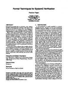
3 The RuleBase Tool RuleBase uses an enhanced version of SMV as its verification engine. SMV [McM93] was developed by Ken McMillan at Carnegie-Mellon University. It is an efficient and robust symbolic model checker that uses binary decision diagrams (BDD) to represent the unit under test. The specification language of SMV is CTL. Our tool, including SMV, provides significant improvement over the bare engine. RuleBase supports several hardware description languages and representation formats, including VHDL and Verilog, and is easily integrable into a variety of design environments. RuleBase has a graphical user interface that allows convenient control over the formal verification process. The user interface facilitates user intervention in the process, while allowing a fully automated verification when the user selects not to intervene. The front panel of RuleBase is shown in Figure 1. Environment models (see Section 2.2) are written in the RuleBase language, a dialect of SMV which supports multiple environments (for instance, a read-only environment, a write-only environment
and a read-write environment). This language includes non-deterministic constructs which allow abstraction and thus a compact description of the full environment’s behavior. The following subsections describe in detail some of RuleBase’s primary features, namely the Sugar specification language, mechanisms for withstanding size problems, and debugging aids.
3.1 Sugar - RuleBase Specification Language The SMV model checker uses CTL [CE81] as a specification language. CTL was designed to have an efficient model-checking algorithm, and yet be expressive enough to specify important properties. However, CTL has one big drawback: although its syntax is very simple, its semantics are difficult to learn and master. Even an expert finds it difficult to understand formulas written by others. Sugar - the RuleBase specification language - provides a way for hardware designers who are not CTL experts to read and write specifications easily. Sugar is built on top of CTL and includes additional language constructs. These constructs are translated by RuleBase into CTL and verified using the standard verification algorithms. Some of the Sugar constructs are described below. More constructs and details, including the exact semantics and claims about expressiveness, can be found in [BBL96].
Within Experience shows that many design behaviors are repetitive, where a basic transaction takes place again and again, and properties are interesting only within the boundaries of a single transaction. The within operator addresses this issue. Its syntax is “within(start, end)(Sugar-formula)”, where start and end are Boolean expressions. The meaning is “check the Sugar formula only in time intervals beginning with start and ending with end”. For example, “AG within(start, end)( AG (request -> AF acknowledge))” means: “in all time intervals delimited by start and end a request must be followed by an acknowledge”.
Next-Event The operator “next_event(p)(q)” has the following meaning: the next time that p occurs, q will occur. For example, “AG((request & requester = high_priority) -> next_event(grant)(granted = high_priority))” means: “if there is a request from a high-priority device, then the next time there is a grant, the higher priority device is the one granted”. Similarly “next_event(p)[n](q)” means that q must occur the nth time that p occurs. For example: “AG(request -> next_event(data)[4](last_data))” means: “last_data should be asserted together with the fourth data after a request”. The CTL equivalent of this formula is: “AG (request -> !E[!data U (data & EX E[!data U (data & EX E[!data U (data & EX E[!data U (data & !last_data ) ]) ]) ]) ])”.
Strong and Weak Operators Most Sugar operators have two forms: strong and weak. The strong form requires an event to happen eventually (liveness property), while the weak form only states that a bad event cannot happen (safety property). An operator becomes strong by appending a ‘!’ to its name. For example, “next_event!(p)[3](q)” (strong version) states that p must happen three times and then q must hold, while “next_event(p)[3](q)” (weak version) states that if p happens three times then q must hold.
Figure 1: RuleBase Front Panel 3.2 Coping with the Size Problem Symbolic model checking [McM93] addressed the state explosion problem by using BDDs. While this was a major advance and made model checking a useful tool for real hardware designs, the size problem is far from being solved. Much effort has been put into RuleBase in order to increase its capacity. Some of the methods are described below:
Automatic, Per-Formula Reduction Usually, a formula is influenced by only part of the design, while other parts are irrelevant to its truth or falsity. For example, if the formula verifies a property of one design output, only this output and its input cone of logic are necessary. RuleBase identifies unnecessary parts and removes them. Knowing the expected behavior of inputs allows RuleBase to reduce the design further. This knowledge is gathered from environment models which are provided by the user (see Section 2.2). The technique is most effective when some of the inputs can be assigned a constant value. This is usually the case with configuration inputs, or data inputs which have no effect on the control. More reduction techniques identify equivalent sub-components which may result from redundant logic or former reductions.
Ordered Partitioned Transition Relation The technique of keeping the transition relation (TR) partitioned was presented in [BCL91] and implemented in SMV. Subsequently, an ordering heuristic for the partitions was described in [GB94]. RuleBase employs these techniques when appropriate. The decision of when to leave the TR partitioned is based on the ratio of number of times the TR must be computed to the number of times it is used. The user can override this decision.
Dynamic BDD Ordering Since SMV, the verification engine, uses BDDs for Boolean function representation and for symbolic computations, a good BDD ordering is essential. We don’t know of any static ordering algorithm which produces satisfactory order for the various functions (TR,
state-sets, next-state functions, etc.). However, we have found the dynamic ordering algorithm described in [Rud93] to be very effective in spite of its simplicity. RuleBase uses a variation of this algorithm, which turns dynamic re-ordering on and off at various points in the verification process, using heuristic knowledge gained through experimentation, and controllable by the user. This improvement is necessary since the ordering process is time-consuming and must be used carefully.
Checking Safety Formulas On-The-Fly Formulas belonging to a subset of the CTL logic can be verified while traversing the reachable state space, without the need for the full model-checking algorithm. This technique has two advantages: (1) The state-space search can stop as soon as an error is detected. (2) If the state-space search is completed without errors, there is no need to continue. Particularly, there is no need to construct a full transition relation. RuleBase can check several safety formulas at a time, producing counter-examples to those formulas which fail without building the full transition relation, and continuing to check the rest. If some of the formulas do not belong to the mentioned subset, RuleBase continues with usual model-checking.
3.3 Debugging Aids As mentioned in Section 2.4, verification results should always be analyzed. In the case of a formula failure, it is obvious that a counter-example is needed. In the case of a success, it is essential to verify that the formula really exercised the design, and the result is not a false positive. RuleBase has various tools to support both kinds of analysis. Some of these tools are described below.
Timing Diagrams RuleBase presents counter-examples and witnesses (see below) as timing diagrams. Given such a timing-diagram, it is easy for designers to locate the problem, since the debugging process is similar to the one employed in traditional simulation-based verification. If a diagram is too crowded with signals and transitions, RuleBase can
be asked to explain the counter-example. The explanation points to the key events (signal, time, value) needed to understand the example.
Test Generation If a user prefers to debug a problem using a simulator, RuleBase creates a control program (test) for simulation, which is used to reproduce the error condition.
Witness and Vacuity When a formula passes successfully, RuleBase tries to produce a witness: an execution trace that demonstrates a non-trivial path on which the formula holds. Analyzing a witness may help to discover unexpected behaviors resulting from over-restriction of environment models. If RuleBase fails to find a non-trivial witness, it means that the formula passed vacuously: some of the conditions leading to the point where the property is to be checked never hold. For instance, in the case of the formula “if a and then b, c must hold”, it may be the case that the sequence “a and then b” never happens, so that the formula passes vacuously. In this case, RuleBase produces an explanation that tells which is the first condition that is not met. In the example above, RuleBase indicates whether a or b is never met.
Formula Explanation and Warnings It is often the case that verification fails because the formula, rather than the design, is incorrect. Although Sugar specifications are considerably more clear that CTL formulas, it is still possible to make an error. The most common error is using temporal operators inside conditions, which usually means something different than what the user intended to say. RuleBase has two solutions to aid the identification of such cases: it produces warnings when it finds “suspicious” formulas, and it can translate a Sugar formula to an English explanation. Several formulation problems have been detected by comparing this explanation with what the user had in mind
4 Comparison to Related Works Formal verification has recently become a topic of much interest in the electronic design community. However, one should distinguish between the different categories of formal verification techniques. Several tools provide equivalence checking between implementation levels, which is important by itself, but is totally different from the functional verification that RuleBase provides. Other tools employ theorem proving techniques, which are more powerful than (propositional) model checking and can probably handle larger designs, but these tools demand users to invest much effort in close guidance of the proof process, contrasted to the fully automated model-checking. Model checking as a technique for hardware verification has been studied in academia at U.C. Berkeley using HSIS [Azi94] and at Carnegie-Mellon University using SMV [McM93]. Several case studies of formal verification in an industrial environment have been published in the past few years [Cla93] [Lon93] [CYF94] [EM95] all of which used SMV as their model checker. These papers, in addition to demonstrating the use of model checking, offer some helpful suggestions and insights as to how to overcome size and expressibility problems. All of these case-studies were done by formal verification experts, rather than by designers. RuleBase’s in-
tention is to make model checking accessible to the general design community. Two model checking tools that have been published in the past year are Verdict [PP95] and CVE [BLPV95]. Both are integrated into the design environment in the sense that they accept standard languages (Verilog and VHDL, respectively). Verdict, like RuleBase, is based on SMV, while CVE has an independent model-checker. It is difficult to compare capacity without the aid of a benchmark, thus we can not give a good comparison on this important issue. Nevertheless, as RuleBase is able to deal with 300 state variable designs, we believe that its capacity is at least comparative with other model checking tools. RuleBase’s specification language, Sugar, is theoretically equivalent in expressive power to the CTL used by SMV, and thus is equivalent in expressive power to Verdict and more expressive than CIL used by CVE. However, many properties (i.e., next_event) are so difficult for the non-expert to express in CTL as to make Sugar more expressive than CTL for all practical purposes. In addition, RuleBase’s debugging aids in the form of support for witnesses to correct formulas and vacuity checking are, we think, unique.
5 Experience First and foremost, the development of RuleBase has been driven by practicality considerations, namely, capacity, robustness and usability. To ensure that the development of RuleBase maintains these requirements, the tool has been used in various verification projects throughout its development. The experience gathered in these verification projects has been applied to adjust and refine the tool and its usage methodology so as to better match the verification challenges. Since 1993, we have used RuleBase to verify many hardware units, both at the architectural and the implementation level. Part of this usage experience is detailed below.
5.1 Experience in Design Verification RuleBase has been applied in the unit verification of various designs in IBM. In this context, the design is essentially an implementation of an architecture, and is checked against a set of rules derived from the architecture specification. Each unit is verified separately, and is occasionally further divided into its constituent blocks, due to size limitations. Typically, a unit subject to formal verification consists of many state machines, some of which are quite large, which communicate with one another. The control logic underlying these state machines is complex and error prone. Data also exists in the form of queues, buffers and arrays. A hardware unit is presented to RuleBase as an RTL description in some HDL. RuleBase performs automatic, per-formula reductions of the unit under verification, thereby scaling down the size by factor of 2 to 10. RuleBase can model-check designs whose size - in reduced form - is some 300 state variables (inputs or latches). In pre-reduction terms, the size of the largest unit verified by RuleBase is up to a few thousands of state-variables of control logic. Following is a partial list of the units which were formally verified using RuleBase: 1. PCI bus bridges, including PCI-to-MicroChannel, PCI-toISA, PCI-to-VESA and PCI-to-PCI bridges [BB+95]. For each bus bridge dozens of PCI rules were written and verified. These included the full PCI specification (basic transfers,
command usage, termination types, arbitration, signal stability, exclusive access etc.) as well as many implementation-level rules (e.g. performance). The following are two sample rules used in these projects: - “In fast back-to-back transactions, the first transaction must be a write command”. - “A PCI slave should not disconnect (STOP#) after FRAME# has been de-asserted”. The formal verification of these units has revealed nearly 200 bugs - including several deadlocks. Three of the chips were fully functional at first silicon realization; the other two were fully functional at second silicon realization. A summary of using RuleBase in the verification of these designs can be found in [BB+95]. 2. An X86 bus interface unit. Rules were written to verify the X86 bus protocol, transaction initiation and completion, split cycles, queue entry, queue promotion, snooping, pipelining and others. Two sample rules used in this project are: - “Writeback cycles and locked cycles are never pipelined.” - “If a snoop hits an address that is in the writeback buffer before the last BRDY of that writeback, then HITM should be asserted 2 clocks later”. The verification of this unit employed a phased methodology where global properties have been verified in the complete unit only after a detailed verification of its constituent components. Nearly 70 bugs have been found by RuleBase in this unit; first silicon realization is functional and currently being tested. 3. An on-line L2-cache for a PowerPC processor. In this unit, formal verification has focused on three key blocks, namely the Processor Interface Unit, the System Interface Unit and the Cache Control Unit. Rules were written to verify the bus protocol, MESI states, data ordering, cache coherency, snoop logic, locked transfers, queuing mechanisms, command priorities, burst transfers, split cycles and others. The following are sample properties verified in this project: - “If a read is requested to an address that already resides in the writeback buffer, do the writeback first”. - “If a system snoop-and-invalidate hits a line in the L2 cache, then the L2 cache must send a snoop and invalidate of the same address to the L1 cache”. Nearly 70 bugs were detected by RuleBase in this unit, which is a significant fraction of the design bugs found altogether with simulation. Details of several verified units of the above projects are summarized in table 1. Size Before Reduction is the total number of latches and inputs in the design unit. Size After Reduction is the resulting
number of state variables (actual reduction depends on the verified formula; we selected the largest representatives). Unit
Size Before Reduction
Size After Reduction
Effort (years)
#Bugs
A
1500
150
1.0
69
B
800
140
0.5
68
C
810
215
0.5
20
D
1200
330
0.5
20
Table 1. Implementation Verification Summary (partial) To summarize our experience, RuleBase has proven to be an extremely successful tool for unit-level design verification. As such, it has been integrated into the verification methodology of the VLSI department in IBM Haifa Research Laboratory (HRL), and is applied to practically all verification projects in HRL. Other IBM developments laboratories are currently considering the integration of RuleBase into their design methodologies. In addition, in the last year we have started to support RuleBase as a tool used directly by designers and verification teams rather than by specialists. Initial experience shows that they can independently use the tool to good effect after a short training period.
5.2 Experience in Protocol Verification In addition to unit-level verification of hardware designs, RuleBase has also been applied to the verification of protocol specifications. In this type of application, the model under verification is not an HDL description to be verified against a specification. Rather, it is the protocol specification itself that is modeled and validated against its required properties. Protocol verification is not restricted to the unit-level, since the protocol can be modeled at a high level of abstraction. Thus formal verification of protocol specifications can be applied to system-level models. RuleBase has been applied to the formal verification of two cache coherency protocols. In the first project, a 3-level directory-based MESI cache coherence protocol was modelled and verified. Formal verification found a number of holes in the specification of the request queue protocol which caused deadlocks in the system. In the second project, a distributed shared-memory MESI cache coherence protocol linking a number of tightly-coupled multi-processors was verified. Formal verification found two holes in the specification resulting in deadlocks in the system, and one coherence violation resulting from a very specific sequence of events. In both projects, the model was coded in the RuleBase language, environments were developed and rules were written, including cache coherence rules, deadlock-freedom rules, MESI rules and correct response to processor requests. The formal verification effort revealed subtle specification bugs which would almost certainly not have been found using simulation. In previous work [EM95] on protocol verification, only AG EF rules were used for verifying the absence of deadlocks. However, our experience has shown that both AG EF and AG AF rules are needed. AG AF rules are needed because a bug in the environment model can cause state machines to non-deterministically return to the idle state, which will allow AG EF rules to pass even if the protocol contains a deadlock. On the other hand, AG AF rules are not sufficient, because they require fairness which, if not carefully
used, has the potential to mask out the very problems that the rule is trying to discover [Lon93], p. 65. Also, they do not verify that every state is reachable from every other state. Therefore, both AG AF deadlock rules as well as AG EF deadlock rules are required in order to ensure absence of deadlock. We have found RuleBase to be a valuable tool for the verification of real-life protocol specifications. If applied early enough, this kind of verification can save much effort by preventing the realization of wrong protocols. Additionally, the formal model developed for the protocol verification has applicability in later design stages, including (1) serving as a basis for actual hardware implementation and (2) laying out a framework for coverage-driven test generation for simulation.
6 Summary Formal verification in an industrial design environment is fast becoming a reality. The most important aspects of a commercial formal verification tool are capacity and ease of use. Three years of experience and development have brought the RuleBase tool to maturity in both aspects. First, its capacity is up to 300 state variables, and up to a few thousand before automatic reduction. Second, RuleBase includes a variety of features to ease its use in a standard design environment: automatic translation from commonly used HDLs, an easy to use specification language, and many debugging aids. As a result, we believe that model checking technology has finally reached the point where hardware designers and verification teams can use formal verification as part of the standard hardware design cycle without the intensive aid of specialists in formal techniques.
DAC’91, pp. 403-407. [CYF94] B. Chen, M. Yamazaki and M. Fujita, “Bug identification of a Real Chip Design by Symbolic Model Checking”, Proc. European Design and Test Conference, 1994, pp. 132-136. [CE81]
[Cla93] E. Clarke et al., “Verification of the Futurebus+ Cache Coherence Protocol”, Proc. 11th Intl. Symp. on Computer Hardware Description Lang. and their Applications, 1993. [EM95] A. Eiriksson and K. McMillan, “Using Formal Verification/Analysis Methods on the Critical Path in System Design: A Case Study”, CAV’95, LNCS 939, pp.367-380. [GB94] D. Geist and I. Beer, “Efficient Model Checking by Automated Ordering of Transition Relation Partitions”, CAV’94, LNCS 818, pp. 299-310. [Lon93] D. Long, “Model Checking, Abstraction and Compositional Verification”, Ph.D. Thesis, CMU, 1993. [McM93] K. McMillan, “Symbolic Model Checking”, Academic Publishers, 1993.
References [Azi94] A. Aziz et al., “HSIS: A BDD-Based Environment for Formal Verification”, DAC’94, pp. 454-459. [BB+94] I. Beer, S. Ben-David, D. Geist, R. Gewirtzman and M. Yoeli, “Methodology and System for Practical Formal Verification of Reactive Hardware”, CAV’94, LNCS 818, pp. 182-193. [BB+95] I. Beer, S. Ben-David, C. Eisner, Y. Engel, R. Gewirtzman, and A. Landver, “Establishing PCI Compliance using Formal Verification: a Case Study”, Intl. Phoenix Conf. on Comp. and Comm. 1995. [BBL96] I. Beer, S. Ben-David, and A. Landver, “Sugar: Syntactic Sugaring of CTL Formulas as a Productivity Aid to Formal Verification”, in preparation. [BLPV95]J. Bormann, J. Lohse, M. Payer and G. Venzl, “Model Checking in Industrial Hardware Design”, DAC’95, pp. 298-303. [BCL91] J. Burch, E. Clark and D. Long, “Representing Circuits More Efficiently in Symbolic Model Checking”,
Kluwer
[PP95]
B. Plessier and C. Pixley, “Formal Verification of a Commercial Serial Bus Interface”, International Phoenix Conference on Computers and Communications, 1995, pp. 378-382.
[RB]
RuleBase Formal Verification Tool: User’s Manual, IBM Science and Technology, Haifa Research Laboratory, contact:
[email protected].
7 Acknowledgments We thank Danny Geist, Gavin Meil, Wayne Nation, Ram Raghavan, Bruce Singer, Yakov Zandman, and the designers of the Haifa Design Group, whose cooperation contributed to the maturity of RuleBase. We also thank Yaron Wolfsthal, Raanan Gewirtzman and Aharon Aharon for supporting this work.
E. Clarke and E. Emerson, “Design and Synthesis of Synchronization Skeletons using Branching Time Temporal Logic”, in proc. Workshop on Logics of Programs, LNCS 131, pp. 52-71, 1981.
[Rud93] R. Rudell, “Dynamic Variable Ordering for Ordered Binary Decision Diagrams”, ICCAD’93, pp. 42-47.