Network virtualization gives each âtenantâ in a data center ... barrier for creating new networked services. ... lar, OpenFlow [3] offers a standard API for installing.
Scalable Network Virtualization in Software-Defined Networks Dmitry Drutskoy
Eric Keller
Jennifer Rexford
Princeton University
University of Pennsylvania
Princeton University
ABSTRACT Network virtualization gives each “tenant” in a data center its own network topology and control over the flow of its traffic. By offering a standard interface between controller applications and switch forwarding tables, Software Defined Networking (SDN) is a natural platform for network virtualization. Yet, supporting a large number of tenants with different topologies and controller applications raises scalability challenges. In this paper, we present the FlowN architecture, which provides each tenant the illusion of its own address space, topology, and controller. The FlowN controller platform leverages database technology to efficiently store and manipulate mappings between the virtual networks and the physical switches. Rather than running a separate controller per tenant, FlowN performs lightweight containerbased virtualization. Experiments with our FlowN prototype, built as an extension to the NOX OpenFlow controller, show that our solution scales to a large number of tenants.
1.
INTRODUCTION
Hosted cloud computing has significantly lowered the barrier for creating new networked services. Likewise, experimental facilities like GENI (http://www.geni.net) enable researchers to perform large-scale experiments on a “slice” of a shared infrastructure. By enabling sharing of physical resources, virtualization is key technology in these infrastructures. While the virtual machine is now the standard abstraction for sharing computing resources, the right abstraction for the network is a subject of ongoing debate. Existing solutions differ in the level of detail they expose to the individual tenants. Amazon EC2 offers a simple abstraction where all of a tenant’s virtual machines can reach each other. Nicira [1] extends this “one big switch” model by offering providing programmatic control at the network edge to enable, for example, improved access control. Oktopus [2] exposes a network topology so tenants can perform customized routing and access control based on knowledge of their own applications and traffic patterns. Each abstraction is most appropriate for a different class of tenants. As more companies move“to the cloud,”
providers must go beyond simple sharing of network bandwidth to support a wider range of abstractions. With a flexible network virtualization layer, a cloud provider can support multiple abstractions ranging from a simple “one big switch” abstraction (where tenants do not need to configure anything) to arbitrary topologies (where tenants run their own control logic). The key to supporting a variety of abstractions is a flexible virtualization layer that supports arbitrary topologies, address and resource isolation, and custom control logic. Our FlowN system provides this virtualization layer. Supporting a large number of tenants with different abstractions raises scalability challenges. For example, supporting virtual topologies requires a way for tenants to run their own control logic and learn about relevant topology changes. Software Defined Networking (SDN) is an appealing platform for network virtualization, since each tenant’s control logic can run on a controller rather than the physical switches. In particular, OpenFlow [3] offers a standard API for installing packet-forwarding rules, querying traffic statistics, and learning about topology changes. Supporting multiple virtual networks with different topologies requires a way to map a rule or query issued on a virtual network to the corresponding physical switches, and to map a physical event (e.g., a link or switch failure) to the affected virtual components. The virtualization solution must perform these mapping operations quickly, to give each tenant real-time control over its virtual network. In this paper we present FlowN, an efficient and scalable virtualization solution. We build on top of SDN technology for programmable control of a network of switches. With FlowN, each tenant can specify its own address space, topology, and control logic. The FlowN architecture leverages advances in database technology for scalably mapping between the virtual and physical networks. Similarly, FlowN uses a shared controller platform, analogous to container-based virtualization, to efficiently run the tenants’ controller applications. Experiments with our prototype FlowN system, built as an extension to the NOX [4] OpenFlow controller, show that these two design decisions lead to a fast, flex-
ible, and scalable solution for network virtualization.
2.
virtual links. Each virtual component can include resource constraints—e.g., the maximum number of flow table entries on the switch, the number of cores on a server, or the bandwidth and maximum latency for virtual links. The cloud provider runs an embedding algorithm [7] to map the requested virtual resources to the available physical resources. Importantly, with full virtualization, the virtual topologies are decoupled from the physical infrastructure. This is in contrast to ‘slicing’ the physical resources (as done with FlowVisor [8]) which also provides tenants with the ability to run their own controller over a portion of the traffic and a subset of the physical network. However, with slicing, the mapping between virtual and physical topologies is visible to the tenants. With FlowN, the mappings are not exposed to the tenants. Instead, the tenants simply see their virtual networks. With this decoupling, the cloud provider can offer virtual topologies with richer connectivity than the physical network, or remap the virtual networks to hide the effects of failures or planned maintenance. Virtual nodes, whether switches or VMs, can move to different physical nodes without changing the tenant’s view of the network.
NETWORK VIRTUALIZATION
For hosted and shared infrastructures, such as cloud computing infrastructure, we argue that full virtualization of a software-defined network is the correct way to represent the network to tenants. In this section we discuss the requirements for virtualization in terms of (i) specification of the virtual infrastructure and (ii) isolation between virtual infrastructures.
2.1 SDN Controller Application To support the widest variety of tenants, the cloud provider should allow each tenant to specify custom control logic on its own network topology. Softwaredefined networking (SDN) is quickly gaining traction as a way to program the network. In SDN, a logicallycentralized controller manages the collection of switches through a standard interface, enabling the software to control switches from a variety of vendors. With the OpenFlow [3] standard, for example, the controller’s interface to a hardware switch is effectively a flow table with a prioritized list of rules. Each rule consists of a pattern that matches bits of the incoming packets, and actions that specify how to handle these packets. These actions include, for example, forwarding out of a specific port, dropping the packet, or sending the packet to the controller for further processing. The software controller is responsible for interacting with the switches (e.g., handling packets sent to the controller) and installing the flow table entries (e.g., installing rules in a series of switches to establish a path between two hosts). With FlowN, each tenant can run its own controller application. Of course, not all tenants need this level of control. Tenants wanting a simpler representation of the network can simply choose from default controller applications, such as all-to-all connectivity (similar to what Amazon EC2 offers) or an interface similar to a router (such as with RouteFlow [5]). This default controller application would run on top of the virtualization layer provided by FlowN. As such, the tenants can decide whether they want full control of the network, or a pre-existing abstraction that matches their needs.
2.3 Address Space and Bandwidth Isolation Each tenant has an address space, defined by the fields in the packet headers (e.g., source and destination IP address, TCP port numbers, etc.). Rather than divide the available address space among the tenants, we virtualize the address space by presenting virtual address spaces to each application. This gives each tenant control over all fields within the header (e.g., two tenants can use the same private IP addresses). To do this, the FlowN virtualization layer provides a mapping between the virtual addresses and the physical addresses. To distinguish between the traffic and rules for different tenants, the edge switches encapsulate incoming packets with a protocol-agnostic extra header, transparent to the tenant’s virtual machines and controller application. This extra header (e.g., VLAN) is simply to identify the tenant – we do not run the associated protocol logic (e.g., per VLAN spanning-tree protocol). In addition to address-space isolation, the virtualization solution must support bandwidth isolation. While current SDN hardware does not include the ability to limit bandwidth usage, the recent OpenFlow specification includes this capability [9]. Using embedding algorithms, we guarantee bandwidth to each virtual link. As support for enforcing these allocations becomes available, we can incorporate them into our FlowN system.
2.2 Virtual Network Topology In addition to running a controller application, each tenant also specifies a network topology. This enables each tenant to design a network for its own needs, such as favoring low latency as in high-performance computing workloads or favoring a high bisection bandwidth in data-processing workloads [6]. With FlowN, each virtual topology consists of nodes, interfaces, and links. Virtual nodes can be either a server (virtual machine) or an SDN-based switch. Each node has a set of virtual interfaces that connect to other virtual interfaces via
3. FLOWN ARCHITECTURE OVERVIEW Hosted cloud infrastructures are typically large datacenters that host many tenants. As such, our virtualization solution must scale in both the size of the physical 2
handlers that respond to network events (e.g., topology changes, packet arrivals, and new traffic statistics) by sending new commands to the underlying switches. Each application should have the illusion of running on its own controller. However, running a full-fledged controller for each tenant is unnecessarily expensive. Instead, FlowN supports container-based virtualization by mapping API calls in the NOX controller back and forth between the physical and virtual networks.
network and the number of virtual networks. Being scalable and efficient is especially critical in softwaredefined networks, where packets are not only handled in the hardware switches but also can be sent to the centralized controller for processing. There are two main performance issues with virtualization in the context of SDN. • An SDN controller must interact with switches through a reliable communication channel (e.g., SSL over TCP) and maintain a current view of the physical infrastructure (e.g., which switches are alive). This incurs both memory and processing overhead, and introduces latency.
4.1 Overhead of Full Controller Virtualization Running a separate controller for each tenant seems like a natural way to support network virtualization. In this solution, the virtualization system exchanges OpenFlow messages directly with the underlying switches, and exchanges OpenFlow messages with each tenant’s controller. This system keeps track of the relationships between physical and virtual components, and whatever encapsulation is applied to each tenant’s traffic. When events happen in the network, the system translates these physical events to one or more virtual events (e.g., the failure of a virtual link or switch, or a packetin event for a particular virtual network), and sends the corresponding OpenFlow message to the appropriate tenant(s). Similarly, when a tenant’s controller sends an OpenFlow message, the virtualization system converts the message (e.g., mapping virtual switch identifiers to physical switch identifiers, including the tenant-specific encapsulation header in the packet-handling rules) before sending a message to the physical switch. The FlowVisor [8] system follows this approach, virtualizing the switch data plane by mapping OpenFlow messages sent between the switches and the per-tenant controllers. Using the OpenFlow standard as the interface to the virtualization system has some advantages (e.g., tenants can select any controller platform), but introduces unnecessary overhead. Repeatedly marshalling and unmarshalling parameters in OpenFlow messages incurs extra latency. Running a complete instance of a controller for each tenant involves running a large code base which consumes extra memory. Periodically checking for liveness of the separate controllers incurs additional overhead. The overhead for supporting a single tenant may not that significant. However, when you consider that the virtualization layer will now have to provide the full interface of switches for each virtual switch (which will outnumber the number of physical switches by at least an order of magnitude), the cumulative overhead is significant—requiring more computing resources and incurring extra, unnecessary latency.
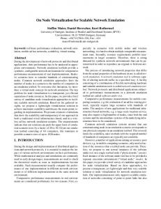
• With virtualization, any interaction between a tenant’s controller application and the physical switches must go through a mapping between the virtual and physical networks. As the number of virtual and physical switches increases, performing this mapping becomes a limiting factor in scalability. In order to overcome these, the FlowN architecture (depicted in Figure 1) is based around two key design decisions. First, as discussed in Section 4, FlowN enables tenants to write arbitrary controller software that has full control over the address space and can target an arbitrary virtual topology. However, we use a shared controller platform (e.g., NOX [4]) rather than running a separate controller for each tenant. This approach is analogous to container-based virtualization such as LXC for Linux or FreeBSD Jails. Second, as discussed in Section 5, we make use of modern database technology for performing the mapping between virtual and physical address space. This provides a scalable solution that is easily extensible as new functionality is needed.
Figure 1: System design
4.2 Container-Based Controller Virtualization 4.
CONTAINER-BASED VIRTUALIZATION
Instead, we adopt a solution inspired by containerbased virtualization, where a shared kernel runs multiple user-space containers with independent name spaces
Each tenant has a controller application that runs on top of its virtual topology. This application consists of 3
and resource scheduling. FlowN is a modified NOX controller that can run multiple applications, each with its own address space, virtual topology, and event handlers. Rather than map OpenFlow protocol messages, FlowN maps between the NOX API calls. In essence, FlowN is a special NOX application that runs its own event handlers that call tenant-specific event handlers. For example, when a packet arrives at the controller, the FlowN packet-in event handler runs. This handler identifies the appropriate tenant (e.g., based on the VLAN tag on the packet) and invokes that tenant’s own packet-in handler. Similarly, if a physical port fails, FlowN’s portstatus event handler identifies the virtual links traversing the failed physical port, and invokes the port-status event handler for each affected tenant with the id of its failed virtual port. Similarly, when a tenant’s event handler invokes an API call, FlowN intercepts the call and translates between the virtual and physical components. For example, suppose a tenant calls a function that installs a packet-handling rule in a switch. FlowN maps the virtual switch id to the identifier of the corresponding physical switch, checks that the tenant has not exceeded its share of space for rules on that switch, and modifies the pattern and action(s) in the rule. When modifying a rule, FlowN changes the pattern to include the tenant-specific VLAN tag, and the actions to forward on the physical port(s) associated with the tenant’s virtual port(s). Then, FlowN invokes the underlying NOX function to install the modified rule in the associated physical switch. FlowN follows a similar approach to intercept other API calls for removing rules, querying traffic statistics, sending packets, etc. Each tenant’s event handlers run within its own thread. While we have not incorporated any strict resource limits, CPU scheduling does provide fairness among the threads. Further, running a separate thread per tenant protects against a tenant’s controller application from not returning (e.g., having an infinite loop) and preventing other controller applications from running.
5.
DATABASE-DRIVEN MAPPINGS
Container-based controller virtualization reduces the overhead of running multiple controller applications. However, any interaction between a virtual topology and the physical network still requires performing a mapping between the virtual and physical spaces. This can easily become a bottleneck. FlowN leverages advances in database technology to overcome this bottleneck.
5.1 Overhead of Virtual Network Mapping To provide each tenant with its own address space and topology, FlowN performs a mapping between virtual and physical resources. The tenants’ packets are encapsulated with a unique header field (e.g., a VLAN 4
tag) as they enter the network. To support a large number of tenants, the switches swap the labels at each hop in the network. This allows a switch to classify packets based on the (i) physical interface port, (ii) label in the encapsulation header, and (iii) fields specified by the tenant application. This enables each switch to uniquely determine the appropriate actions to perform. Determining these labels is the responsibility of the virtualization software running on controller. A virtualto-physical mapping occurs when an application modifies the flow table (e.g., adding a new flow rule). The virtualization layer must alter the rules to uniquely identify the virtual link or virtual switch. A physical-tovirtual mapping occurs when the physical switch sends a message to the controller (e.g., when a packet does not match any flow table rule). The virtualization layer must demultiplex the packet to the right tenant (and identify the right virtual port and virtual switch). These mappings can either be one-to-one (as in the case of installing a new rule or handling a packet sent to the controller) or one-to-many (as in the case of link failures that affect multiple tenants). In general, these mappings are based on various combinations of input parameters and output parameters. Using a custom data structure with custom code to perform these mappings can easily become unwieldy, leading to software that is difficult to maintain and extend. More importantly, this custom software would need to scale across multiple physical controllers. Depending on the complexity of the mappings, a single controller machine eventually hits a limit on the number of mappings per second that it can perform. To scale further, the controller can run on multiple physical servers. With custom code and in-memory data structures, distributing the state and logic in a consistent fashion becomes extremely difficult. This custom data structure is the approach taken by FlowVisor [8]. Though FlowVisor does not provide full virtualzation (it instead slices the network resources), it must still map an incoming packet to the appropriate slice. In some cases, hashing can be used to perform a fast lookup, However, this is not always possible. For example, for the one-to-many physical to virtual mappings (e.g., link failure), FlowVisor iterates over all tenants, and for each tenant it performs a lookup with the physical identifier.
5.2 Topology Mapping With a Database Instead of using an in-memory data structure with custom mapping code, FlowN uses modern database technology. Both the topology descriptions and the assignment to physical resources lend themselves directly to the relational model of a database. Each virtual topology is uniquely identified by some key, and consists of a number of nodes, interfaces, and links. Nodes con-
6. EVALUATION
tain the corresponding interfaces, and links connect one interface to another. The physical topology is described in a similar fashion. Each virtual node is mapped to one physical node; each virtual link becomes a path, which is a collection of physical links and a hop counter giving the ordering of physical links. FlowN stores mapping information in two tables. The first table stores the node assignments, mapping each virtual node to one physical node. The second table stores the path assignment, by mapping each virtual link to a set of physical links, each with a hop count number that increases in the direction of the path. Mapping between virtual and physical space then becomes a simple matter of issuing an SQL query. For example, for packets received at the controller for software processing, we must remove the encapsulation tag and modify the identifier of which switch and port the packet was received on. This can be realized with the following query:
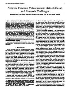
FlowN a scalable and efficient software-defined network virtualization system In this section, we compare our FlowN prototype with unvirtualized NOX (to determine the overhead of the virtualization layer) and FlowVisor (to evaluate scalability and efficiency). We built a prototype of FlowN by extending the Python NOX version 1.0 OpenFlow controller [4]. This controller runs without any applications initially, instead providing an interface to add applications (i.e., for each tenant) at run time. Our algorithm for embedding new virtual networks is based on the work of Chowdhury, et. al. [7]. The embedder populates a MySQL version 14.14 database with the mappings between virtual and physical spaces. We implement all schemes using the InnoDB engine. For encapsulation, we use the VLAN header, pushing a new header at the ingress of the physical network, swapping labels as necessary in the core, and popping the header at the egress. Alongside each database replica, we run a memcached instance which gets populated with the database lookup results and provides faster access times should a lookup be repeated. We run our prototype on a virtual machine running Ubuntu 10.04 LTS given full resources of three processors of a i5-2500 CPU @ 3.30GHz, 2 GB of memory, and an SSD drive (Crucial m4 SSD 64GB). We perform tests by simulating OpenFlow network operation on another VM (running on an isolated processor with its own memory space) using a modified cbench [10] to generate packets with the correct encapsulation tags. We then measure the latency by measuring the time between when cbench generates a packet-in event and when cbench receives a response to the event. The virtual network controllers for each network are simple learning switches that operate on individual switches. In our setup, each new packet-in event triggers a rule installation, which is received by the cbench application. While it is difficult to directly compare FlowN and FlowVisor since they are performing different functionality, as seen in Figure 2, FlowN has a much slower increase in latency than FlowVisor as more virtual networks are run. FlowVisor has lower latency for small numbers of virtual networks as the overhead of using a database, as compared to a custom data structure, dominates at these small scales. However, at larger sizes (e.g., around 100 virtual networks and greater), the scalability of the database approach used in FlowN wins out. We also note that the overall increase in latency over the unvirtualized case is less than 0.2ms for the prototype using memcached and 0.3ms for the one without.
SELECT L.Tenant_ID, L.node_ID1, L.node_port1 FROM Tenant_Link L, Node_T2P_Mapping M WHERE VLAN_tag = x AND M.physical_node_ID = y AND M.tenant_ID = L.tenant_ID AND L.node_ID1 = M.tenant_node_ID
Other events are handled in similar manner, including lookups which yield multiple results (e.g., when a physical switch fails and we must fail all virtual switches currently mapped to that physical switch). While using a relational database reduces code complexity, the real advantage of using a database is that we can capitalize on years of research to achieve durable state and a highly scalable system. As we expect many more reads than writes in this database, we can run a master database server that handles any writes to the database (e.g., for topology changes and adding new virtual networks). Multiple slave servers are then used to replicate the state across multiple servers. Since the mappings do not change often, caching can then be utilized to optimize for mappings that frequently occur. With a replicated database, the FlowN virtualization layer can be partitioned across multiple physical servers (co-located with each replica of the database). Each physical server interfaces with a subset of the physical switches—and performs the necessary physical to virtual mappings. Each physical server is also responsible for running the controller application for a subset of tenants and performing the associated virtual to physical mappings. In some cases, a tenant’s virtual network may span physical switches handled by different controller servers. In that case, FlowN simply sends a message from one controller server (say, responsible for the physical switch) to another (say, running the tenant’s controller application), over a TCP connection. More efficient algorithms for assigning tenants and switches to servers is an interesting area for future research.
7. RELATED WORK Network virtualization has been proposed in various contexts. In early work, ATM switches are partitioned 5
[3]
[4]
[5]
Figure 2: Latency vs. Virtual Network count [6] into “switchlets” to enable dynamic creation of virtual networks [11]. In industry, router virtualization is already available in commercial routers [12]. This then enables the use of virtualization to enable multiple service providers to share the same physical infrastructure, as with VINI [13], or as a means for a single provider to simplify management of a single physical infrastructure among many services, as with ShadowNet [14]. More recently, network virtualization solutions in the context of software-defined networks have been introduced [1, 8, 15] to compliment the virtualized computing infrastructure in multi-tenant datacenters. While a lot of work has been done for network virtualization in the SDN environment, the current solutions differ from our approach in their approach to splitting the address space and virtual topology representation. With FlowN we provide full virtualization of the address space and the topology, with a scalable and efficient system.
8.
[7]
[8]
[9]
[10]
[11]
CONCLUSIONS
In this paper we presented FlowN which provides a full network virtualization solution for software defined networks. The FlowN architecture is based around the use of namespaces where the controller platform is shared by each virtual network for an efficient solution. We make use of database technology which has been developed to support such features as replication and caching for mappings between virtual and physical spaces. The evaluation of our prototype shows that FlowN is a scalable and efficient solution.
9.
[12]
[13]
[14]
REFERENCES
[1] Nicira, “Network virtualization platform.” http://nicira.com/en/ network-virtualization-platform. [2] C. Wilson, H. Ballani, T. Karagiannis, and A. Rowstron, “Better never than late: Meeting
[15]
6
deadlines in datacenter networks,” in ACM SIGCOMM, August 2011. N. McKeown, T. Anderson, H. Balakrishnan, G. Parulkar, L. Peterson, J. Rexford, S. Shenker, and J. Turner, “OpenFlow: Enabling innovation in campus networks,” ACM SIGCOMM CCR, vol. 38, no. 2, pp. 69–74, 2008. N. Gude, T. Koponen, J. Pettit, B. Pfaff, M. Casado, N. McKeown, and S. Shenker, “NOX: Towards an operating system for networks,” ACM SIGCOMM CCR, vol. 38, no. 3, 2008. M. R. Nascimento, C. E. Rothenberg, M. R. Salvador, C. N. A. Corrˆea, S. C. de Lucena, and M. F. Magalh˜ aes, “Virtual routers as a service: The RouteFlow approach leveraging software-defined networks,” in Conference on Future Internet Technologies (CFI), June 2011. K. Webb, A. Snoeren, , and K. Yocum, “Topology switching for data center networks,” 2011. N. Chowdhury, M. Rahman, and R. Boutaba, “Virtual network embedding with coordinated node and link mapping,” in IEEE INFOCOM, pp. 783–791, April 2009. R. Sherwood, G. Gibb, K.-K. Yap, G. Appenzeller, M. Casado, N. McKeown, and G. Parulkar, “Can the production network be the testbed?,” in Operating Systems Design and Implementation, October 2010. “Openflow switch specification 1.3.0.” https://www.opennetworking.org/images/ stories/downloads/specification/ openflow-spec-v1.3.0.pdf, April 2012. “Openflow operations per second controller benchmark.” http: //www.openflow.org/wk/index.php/Oflops, March 2011. J. van der Merwe and I. Leslie, “Switchlets and dynamic virtual ATM networks,” in IFIP/IEEE International Symposium on Integrated Network Management, May 1997. “Configuring virtual routers.” http://www.juniper.net/techpubs/software/ erx/junose80/swconfig-system-basics/html/ virtual-router-config.html. A. Bavier, N. Feamster, M. Huang, L. Peterson, and J. Rexford, “In VINI veritas: Realistic and controlled network experimentation,” in ACM SIGCOMM, August 2006. X. Chen, Z. M. Mao, and J. van der Merwe, “ShadowNet: A platform for rapid and safe network evolution,” in USENIX Annual Technical Conference, June 2009. NEC, “ProgrammableFlow Controller.” http://www.necam.com/PFlow/doc.cfm?t= PFlowController.