SculptUp: A Rapid, Immersive 3D Modeling Environment Kevin Ponto∗
Ross Tredinnick† Aaron Bartholomew‡ Carrie Roy§ Daniel Greenheckk Joe Kohlmann∗∗
Dan Szafir¶
University of Wisconsin–Madison 1
I NTRODUCTION
Modeling complex objects and effects in mainstream graphics applications is not an easy task. Users often require months, or even years, to adapt to interfaces used in creating compelling computer graphics. Consequently, novice users face an imposing barrier to entry in fully utilizing three-dimensional graphics as an artistic medium. To address these challenges, we present SculptUp, an immersive modeling system based on a real-world sculpting and painting interaction paradigm, which affords fast, intuitive generation of complex CGI. SculptUp runs in a Cave Automatic Virtual Environment. Users interact with the virtual environment through a handheld wand and voice recognition. There are two unique states of manipulation that the user switches between: sculpt mode and world mode. In sculpt mode, the user can create and modify volumetric material, modeled as isosurfaces, using a minimalist control scheme. This control scheme allows the user to make highly detailed objects by arbitrarily adding, subtracting, and painting isosurfaces similarly to how a user would sculpt a clay model in reality. Users can also change paint and volumetric colors through a speech-based interface. In world mode, users operate in an OGRE scene where they can use detailed volumetric models to design the salient features of a largescale scene. All work can be exported from the SculptUp system into a rendering environment for the production of high quality images as in Figure 1. Ultimately, SculptUp’s interface substantially expedites creative processes and catalyzes rapid scene prototyping. 2
M ETHOD
The SculptUp system consists of two unique states of manipulation that the user switches between: sculpt mode and world mode. 2.1
Sculpt Mode
The SculptUp system utilizes fast GPU centric volumetric manipulation and visualization to enable a simple user experience. The system utilizes 3D framebuffer objects which remove the need to transfer data between the CPU and GPU. This 3D texture holds an intensity value in its alpha channel used for determining geometry and color information in its RGB channels for each voxel. The volume is sized to be one meter in dimension with a spatial resolution of 7.8 mm per voxel. Changes are made to the VolumeBuffer by running a fragment shader program and rendering slices of the volume sequentially. Realtime meshing is accomplished using the marching-cubes algorithm using a geometry shader. Normals and colors are generated using a fragment program [1]. This allows the volume to be fully rendered and manipulated in realtime, a necessity for immersive virtual systems. Users can manipulate the volume in several ways: Addition : Users can add to the volume in two ways, either as spheres or cubes. In the sphere mode, when the user presses a but∗ e-mail: † e-mail: ‡ e-mail: § e-mail: ¶ e-mail: k e-mail: ∗∗ e-mail:
[email protected] [email protected] [email protected] [email protected] [email protected] [email protected] [email protected]
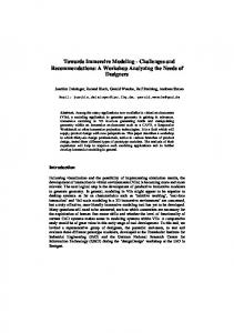
Figure 1: A scene created using the SculptUp system rendered in Maya. The entire scene took less than nine minutes to create.
ton, the volumetric data continually adds to the intensity volumetric data channel with an inverse distance squared radial falloff from the tip of the wand controller inside of the fragment program. This approach gives a similar feel to Metaballs as shapes can be easily merged together [2]. This method is useful for generating organic structures. The second method of volumetric manipulation is the cube mode, in which a user specified region is filled in completely. This is generally useful for inorganic structures. The color of the volume for all new additions will be the currently selected color, while adding new material near pre-existing material will cause the colors to be blended together correspondingly. Removal : Users can remove volume using a tool that visually resembles a light beam jetting out from the tip of the wand controller. The beam is resizable (radius and length) using the joystick on the wand interface. The intensity volumetric data determined to be inside of the beam is removed using point-to-line distance calculation inside of the fragment program. Paint : Users can virtually spray-paint onto the sculpted objects at any point during the sculpting process. This method is similar to the Addition tool where the color of the volume is interpolated between the painting color and previous color using an inverse
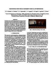
Figure 2: A user generating a tree model in the SculptUp system inside of a CAVE environment.
IEEE Symposium on 3D User Interfaces 2013 16-17 March, Orlando, FL, USA 978-1-4673-6098-2/13/$31.00 ©2013 IEEE
199
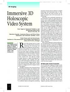
Figure 3: A series of models, each made in under 10 minutes using the SculptUp system. All images were rendered in Maya.
distance squared radial falloff from the tip of the wand controller. Users can change the size of the color manipulation using the joystick on the wand device. ColorSelection : Users can change the color of the addition or paint tool using a voice based interface. The SculptUp system utilizes the Microsoft Kinect Speech SDK for voice processing. Users speak the trigger phrase ”color change” and then ask for a given color from an inventory of 44 colors. The trigger phrase was used to prevent inadvertent change of color through casual conversation. 2.2
World Mode
When users have finished sculpting they can bring the objects into a standard object manipulation interface. We use the OGRE graphical environment for model rendering in this space. The volumetric data is read from the GPU and a CPU based marching cubes is used to tesselate the data. This tessellation is then used to create an OGRE mesh that can be transformed. The user can select an object by pointing a beam from the wand device at an object. From this, the user can translate the object, scale the object, and rotate the object. The user can also duplicate an object to create multiple instances of the same geometry, as shown in the fence for Figure 4. 2.3
Integration
We created a scene and model exporter to expand the utility of the SculptUp system. In order to a maintain the per-vertex-color generated by our sculpting process, we chose to use the ply model format. Following scene creation, positioned model files are saved to disk. These files can be easily read into most modeling environments. 3
R ESULTS
The SculptUp system enables the rapid creation of 3D models. All of the models in Figure 3 were created in under five minutes. Scenes such as Figure 1 and 4 could be easily created in ways that would be extremely difficult in traditional modeling systems. The SculptUp system has been demonstrated to several individuals. User comments were extremely positive about the experience
and control over the modeling environment. We selected four individuals who lacked prior experience with SculptUp for more specific feedback. Of these individuals, three were also novices to CAVE environments. After receiving a small tutorial on system button mappings, the users were given 15 minutes to create a scene of their choice using the system. Upon completion, each user was given a 14-item questionnaire used to evaluate their subjective experiences across the following criteria: User Interface : ease in which a user is able to understand and adapt to SculptUp in order to be productive. Example questions: “The user interface made sense to me” and “I imagine most people would learn to use this application quickly”. Experience : user satisfaction with SculptUp compared to other modeling experiences. Example questions: “I would enjoy using this application frequently” and “I did things with the application that I have never done before with similar tools”. Capability : degree to which users felt they could use SculptUp to design models and scenes. Example questions: “I thought it was easy to model the intended items” and “I thought it was easy to add colors to different parts of my models”. The score for each criteria was determined by averaging all of the individual responses across all of the questions in the category. The User Interface score was mostly positive, with a mean of 3.54 out of 5. Most of the negative responses came from unfamiliarity with the CAVE interface. Users who had never used a CAVE before felt less confident than users who had. Users unanimously felt that given more time they could use the interface competently. The Experience criteria score was exceptionally positive, with a mean of 4.5. Users overwhelming enjoyed using SculptUp, with every user responding 5 when asked if they had a lot of fun using the application. Additionally, every user provided a 5 when asked if they felt they we’re able to do things using SculptUp that they hadn’t been able to do with similar modeling tools. Finally, the Capability criteria score was mixed, with a mean of 3.5. Overall, users were not disappointed with the limitations of the SculptUp system, but they did not feel like they had the capability to competently model their intended object. Given time, training, and a specialized toolset, these shortcomings might be overcome. 4
C ONCLUSION
SculptUp enables the easy creation of complex scenes within a CAVE. Scene creation is achieved through two modes, a sculpt mode that allows free form model creation, plus a world mode, that allows placement, transformation, and duplication of these models. Future work will target the integration of other types of input devices for a more refined means of model creation. R EFERENCES
Figure 4: A farm scene constructed using the SculptUp system rendered in Maya. The fences were created from duplicating the posts in world mode.
200
[1] W. E. Lorensen and H. E. Cline. Marching cubes: A high resolution 3D surface construction algorithm. In SIGGRAPH ’87: Proceedings of the 14th annual conference on Computer graphics and interactive techniques. ACM Request Permissions, Aug. 1987. [2] G. Wyvill, C. McPheeters, and B. Wyvill. Data structure forsoft objects. The Visual Computer, 2(4):227–234, Aug. 1986.