Segmentation of cortical surface and interior brain structures using active surface / active volume templates David J. Schlesinger1, John W. Snell2, Lois E. Mansfield3, James R. Brookeman4, J. Hunter Downs III1, James M. Ortega5, and Neal F. Kassell6 1
Neurovisualization Laboratory, Virginia Neurological Institute 2 Multimedia Medical Systems 3 Dept. of Applied Mathematics 4 Department of Radiology 5 Department of Computer Science 6 Department of Neurological Surgery University of Virginia, Charlottesville, VA 22903
ABSTRACT Advanced applications such as neurosurgical planning and simulation require both surface and interior anatomical information in order to be truly effective. We are developing a segmentation scheme based on collections of active surface templates embedded within an active volume. This composite system encodes high-level anatomical knowledge of both cortical surface and interior brain structures in a self-assembling model of a reference, or atlas brain. Following initialization of the surface templates in the test brain volume, the cortical surface templates deform to achieve a segmentation of the surface of the brain. The displacements of the cortical surface templates cause an increase in the potential elastic energy of the active volume, and a subsequent minimization of this elastic energy is used to define a volumetric warp between the reference brain and the test data. This warp is used to deform the active surface models of the deep structures in the brain to their approximate final configurations, after which a further energy minimization step achieves a final segmentation of the deep structures. The method uses the results of the surface segmentation step as a-priori information regarding the likely deformation of the deep surface models. Initial tests illustrate the potential of the system in regard to the segmentation of cortical surface and deep brain anatomy. Results will be analyzed in terms of improvements that will increase the efficacy if the system. Keywords: deformable surfaces, active surfaces, active volumes, deformable brain atlases, image segmentation
1. INTRODUCTION Segmentation of the cortical surface of the brain and its major sub-components has provided a wealth of information to researchers and applications in the form of quantitative measurements of volume and surface area, as well as the ability to visualize surface anatomical information such as sulci and gyri. Advanced applications such as surgical planning take advantage of this information by allowing surgeons to plan procedures so as to avoid critical surface structures and minimize collateral damage to the brain. For surgical planning systems to be truly effective, however, the ability to visualize and quantitatively analyze deep brain structures is vital. Currently, most deep brain information is available only after a laborious manual segmentation process involving the resources of specialists trained in neuroanatomy.
1
Further author information D.J.S. (Correspondence): Email:
[email protected]; WWW: http://www.nvl.virginia.edu/~djs9c/index.html J.W.S.: Email:
[email protected]
In past work, our lab presented a semi-automatic segmentation method based on the use of active surface templates1,2. In this scheme, generalized models of the cortical surfaces of the major components of the brain (cerebrum, cerebellum, etc.) are developed. These models are initialized and grossly registered with the patient’s anatomical data within the image volume. The surfaces are then allowed to deform to minimize their total energy, which is defined as a function of both an internal elastic force and external image-based force. Following this deformation, the image data outside of the surfaces is removed, leaving only the information pertinent to the brain. This data may be used subsequently for the quantitative measurements and visualization tasks described above. Deformable atlases have been proposed to achieve delineation of deep brain structures 3,4,5,6,7. In this technique, a reference volumetric data set, or atlas, is developed which has all salient anatomical information delineated. This atlas is then deformed to match the individual characteristics of a given patient’s anatomy. Given an accurate correspondence between the atlas data and the patient data, all salient anatomy patient’s brain will be identified. This paper presents a scheme for segmentation of both cortical surface and deep brain structures which represents a hybrid between our previous active surface method and the deformable atlas methods. This composite system encodes high-level anatomical knowledge of both cortical surface and interior brain structures from a reference brain, or atlas, in a selfassembling active surface model. Following initialization in the test brain volume, the cortical surface templates automatically deform to achieve a segmentation of the surface of the brain. The displacements of the cortical surface templates cause an increase in the potential elastic energy of the active volume, and a subsequent minimization of this elastic energy is used to define a volumetric warp between the reference brain and the test data. This warp is used to deform the active surface models of the deep structures in the brain to their approximate final configurations, after which further energy minimization achieves a final segmentation of the deep structures.
2. GENERAL STRATEGY Figure 1 outlines the general strategy for our active surface/active volume method. Anatomical models developed from a reference data set, or atlas, are warped to match the individual characteristics of the patient anatomy from a global level to progressively more local levels. At each step of the process, we wish to apply as much a-priori information about neuroanatomy as possible in order to limit the search space for a solution to the segmentation problem.
Global
Global registration of atlas and test volumes Deformation of atlas-derived cortical surface active templates Energy minimization of active volume template Volumetric warp of atlas-derived interior surface active templates
Local
Final deformation of interior active surface templates Figure 1: General strategy
The purpose of this paper is to address the middle three steps of the method as displayed in the figure. A description of our atlas-based active surface and active volume templates will be presented, followed by a discussion of how these templates work together to define a local volumetric warp for the points in the image volume. Preliminary tests will be presented which
illustrate the potential of the system in regard to the segmentation of cortical surface and deep brain structures. The results of the preliminary test will be analyzed in terms of improvements that will increase the efficacy of the system.
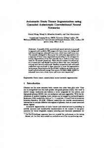
3. ATLAS-BASED DEFORMABLE MODELS 3.1 Cortical surface template and deep brain template creation Atlas-based models for both the surface and interior structures of the brain are created through the definition of multiple active surface templates. A T1-weighted, 3D-MPRAGE volumetric MR study of a normal subject was chosen as a reference (atlas) study for the purpose of this paper. Cortical surface templates were derived from this study by mapping a set of handdelineated contours representing the generalized shape of the reference brain to a set of geodesic-based active surface templates as described in Schlesinger, et al2. These active surfaces were then deformed to match the reference brain, and the resulting final positions of the active surface templates were stored as a reference cortical surface model.
Figure 2: Reference data set with active surface model embedded in an active volume model
The amygdala was chosen as a test interior anatomical model because of its location deep in the head, as well as its fairly good definition and contrast in typical T1-weighted image sequences, which facilitates evaluation of test results. Active surface templates for the amygdala were created by mapping geodesic active surfaces to hand-delineated contours defined on the reference data set. Figure 2 shows the complete active surface model of the brain as derived from the reference data set. The complete test model includes active surface templates for the left and right cerebrum, the left and right cerebellum, and areas encompassing the left and right amygdala. The models are shown embedded in an active volume template (the active volume appears as the grid over the image).
3.2 Active surface / volume templates The active surface and active volume templates used in this study evolved from our previous work, and are an extension of the active contour method described by Kass, et al.8. Each template is treated as an energy-minimizing spline whose behavior is controlled by a set of intrinsic and extrinsic constraints. The intrinsic constraints give the templates a flexible material, “elastic”-like property, while the extrinsic constraints allow salient features from the image data to guide the template deformations to a relevant final configuration. The equation of motion for the surface templates may be written as:
2 2 − w ∂ v + ∂ v = f ( v ) ∂x 2 ∂y 2
(1)
where v is a parametric representation of the template, and w controls its relative elasticity. The left side of (1) represents the intrinsic constraints acting on the template. The right side, f(v), represents the extrinsic forces which deform the template according to features in the image data. These extrinsic forces are defined as:
f (v ) =
δP(v ) δv
(2)
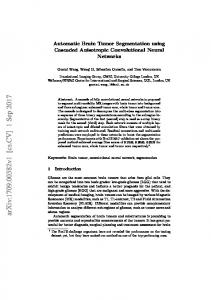
The image potential function, P(v), defines the image features which are used as forces to guide the template deformations. A commonly used image force is the magnitude of the image gradient. In the case of the cortical surface templates, we follow our previous work, and utilize the vector distance transform (VDT) of the image as a potential function2. The VDT returns distance values from a given point to the surface of the object (usually defined by a simple thresholding function). Figure 3 shows an example of a slice of an image, as well as its VDT.
Figure 3: a) Original image slice
b) Vector distance transform
The VDT eliminates local minima which can potentially snag the surface templates, and in our experience provides a very stable energy surface in which the templates deform. The equation of motion for the templates is a departure from that presented in our past descriptions of active surface templates. In those works, the equations of motion for surfaces contained both a second order term responsible for controlling the elasticity of the surface, as well as a fourth order term controlling the rigidity of the surface. Empirical evidence has shown2 that because the templates are surfaces in a 3D space, they are already constrained to the point that it is difficult for undesirable cases such as self-intersection to occur. A similar observation was made for active contours in Caselles, et al9. One of the side benefits of eliminating a high-order term for the equation of motion is that it becomes simple to develop surfaces based on many different mappings of nodes. This can be seen from (3), which is a discrete approximation for the equation in (2):
v0 =
[
]
1 α(v 1 + v 2 + v 3 + v 4 +...+ v N ) + f (v 0 ) Nα
(3)
where v0 is the template node being examined, v1….N are the neighboring nodes of v0, and N is the number of neighbors. Because (3) allows variable node connectivity, we can develop active surface templates based on a large variety of base template structures. Figure 4a) shows the node connectivities for a 5-connected node of a geodesic-based active surface. We have also developed surface templates based on cylinders and volumes, which are presented below, however any configuration of points could conceivably be used to achieve different template behaviors.
6
1
5
z
2
0
4 2 1 0
x 3
4
3
y
5
a) geodesic-based active surface node b) active volume node Figure 4: Node configuration and connectivity as used in equation (3) 3.3 Active volume templates In order to use the displacements of the cortical surface templates as a-priori constraints on a volumetric warp, we developed the active volume template. The template is constructed as a three-dimensional, 6-connected array of nodes, forming an array of hexahedral cells. The grid deforms in a manner similar to that of the active surface templates. The same equations apply, with N=6 because each node in the volume has 6 neighboring nodes. The active volume may also be defined as having static or dynamic boundaries. Static boundaries mean the external faces of the volume remain fixed in space. This provides a boundary constraint for deformations of the rest of the volume. In addition, any given node in the volume may be designated as static, providing a means for further boundary constraints. Figure 4 b) shows the connectivity for a single node of the active volume corresponding to equation (3).
4. MODEL INTERACTION The deformable models introduced above are allowed to interact as they deform through a dynamic linking process. Dynamic linking was introduced in previous work as a method of modeling each active surface template as a deformable solid to prevent one surface from colliding with and passing through another model as they deformed2. In this study, the role of dynamic linking has been expanded to facilitate the transfer of elastic deformation energy from the cortical surface templates to the deep surface templates by allowing the cortical surface templates to dynamically link not only to themselves, but also to the active volume template as they deform.
3x3x3 voxel neighborhood
Figure 5: Spring link established between colliding template nodes As each template deforms, it tests for node collisions with the other templates in the model. For each node on the template, a small neighborhood of voxels surrounding the node is identified and tested for the presence of nodes from other templates. If a node is present in one of the neighborhood voxels whose position is less than a given threshold, the nodes are considered to be in collision, and a link is established between the two nodes. Each node is limited to a pre-determined maximum number of links in order to limit the computational cost of collision searching. Figure 5 illustrates the collision detection process.
The links between nodes which have collided are modeled as springs, and are represented as an additional force in the extrinsic constraint f(v) term of the equation of motion given in (1). The equation for a spring force may be written as:
f spring = − k d − l natural
(4)
where k is the spring constant, d is the vector distance between the two nodes, and lnatural is the natural length of the spring10. For our purposes, l natural is generally set to 0 so the linked nodes remain tightly coupled throughout the deformation.
5. METHODS 5.1 Global registration of atlas-derived model The complete segmentation occurs over several phases. Initially, the atlas-derived active surface templates for both the cortical and deep surface models are grossly initialized to the test data set to remove any global translational and rotational differences between the model and the data to be segmented. Once registered, the volumetric image space is enclosed by an active volume. The edge faces of the active volume lying along the image boundaries are set as static, and will remain in place throughout the ensuing deformation. Figure 6 shows the initial configuration of the model and volume.
Figure 6: Initial configuration of cortical surface models and active volume
5.2 Cortical surface deformation Following global registration of the model, the cortical active surface templates are allowed to deform by the methods presented in section 3.1. The test data is thresholded and the vector distance transform is used to define an energy surface which drives the cortical surface templates to their final configuration. The VDT forces the cortical surface templates to seek a minimum energy configuration which corresponds to the CSF space just outside the cortical surface of the brain. The templates continue to deform until the number of template nodes moving more than a minimum distance falls below a threshold. The final configuration of the surfaces yields patient-specific anatomical information concerning the shape and orientation of the test brain.
5.3 Surface linking and volume stretching As the cortical surface templates are deforming, they actively test for collisions and set up dynamic links between themselves and also with the active volume. The elastic properties of the active volume are disabled for this phase of the segmentation
process, so once links are established with the active volume, the linked volume nodes deform passively along with the active surface. As the nodes in the active volume link to the surfaces and begin to displace, the potential elastic energy of the active volume increases. The deformation of the active volume along with the cortical surface templates effectively allows a transfer of elastic deformation energy from the cortical surfaces to the active volume. Figure 7 shows the status of the cortical active surfaces and the active volume at the end of this initial phase of deformation.
Figure 7: Cortical surface model and active volume after cortical template deformation
5.4 Active volume energy minimization At the beginning of the volume energy minimization phase, all points on the active volume which were linked to nodes on the cortical surface templates are set as static and are held in place. The volume is then allowed to minimize its global energy using the methods outlined in section 3.2. The extrinsic constraints in equation (1) are set to zero in this case. The volume deforms solely by releasing and minimizing its stored potential elastic energy. This process causes the potential elastic deformation energy stored in the active volume in the previous deformation phase to be released as a global deformation of the active volume. The deformation is constrained by the nodes which were set as static and do not deform, as well as the nodes on the edges of the volume which have also been set as static. Figure 8 shows two instances in this volume energy minimization phase. The spread of nodal displacements in the active volume is due to minimization of potential elastic energy. The resulting deformation defines a volumetric displacement field which can be used to deform data points within the test data volume. 5.5 Internal surface template deformation Following the final displacement of the volume template, displacements between the initial and final positions of each node of the volume template are calculated. Corresponding displacements for nodes on the internal surface templates are then computed by interpolating nodal displacement values from cells in the active volume. Because each cell of the deformed volume is a distorted hexahedron, nodal interpolation is a nonlinear problem11. Standard numerical solutions such as Newton’s method may be used to solve the resulting system of equations. As an alternative, the problem may be linearized by regarding each hexahedral cell of the volume as five unique tetrahedrons. Interpolations are then performed based on each tetrahedron. The interpolation allows the internal surface templates to be transformed to the locations specified by the volumetric warp.
Figure 8: a) Early energy minimization phase
b) Late energy minimization phase
5.6 Final internal surface deformation The volumetric warp defined in section 5.5 is intended to define a local nonlinear mapping between nodes on the internal surface models as derived from the reference data set, and the approximate corresponding positions of the nodes in the test data set. Once the internal active surfaces have been warped to an approximation of their final positions, they may undergo a further deformation to reach their final configuration, which should bring them into correspondence with the anatomical shape of the deep structures of interest. This final deformation lies in the future scope of this project, and will not be discussed in detail now, however the final deformation is a process similar to the initial deformation of the cortical surface models outlined in section 5.1. The internal surface templates deform based on salient image features and attempt to minimize both their intrinsic elastic energy as well as their external, image based energy.
6. RESULTS 6.1 Experiment description The method was tested using two T1-weighted MP-RAGE12 volumetric MR sequences (256 x 256 x 128 voxels). One study was determined to be of a normal subject, and was used as a reference (atlas) data set. It was from this data set that the anatomical surface models were derived, as discussed above. The second study was used as a test data set. The reference-derived anatomical models for both the cortical surface and interior (amygdala) structures were globally initialized in the test MR volume. Deformation of the cortical surface models and the active volume model were allowed to proceed as outlined in section 5. In our initial tests of the system, we warped the actual image data in the test MR volume according to the interpolated global deformation field rather than the interior surface templates in order to facilitate visualization of the results and identify weaknesses in the system. 6.2 Initial tests Figure 9 shows the results of an initial test of the volumetric warping scheme. 9 a) shows the original test volume. Notice the gray sulcal pattern near the tip of the arrow in the image. 9 b) shows a slice through the active volume illustrating the local deformations that occurred in the area of the slice of the volume in a). 9 c) shows the deformation of the active volume through the slice in a). Because we are warping from a test data set to a reference dataset, it would be expected that the image data appearing in the warped data set would originate in the test data set at the position of the displacements shown by the arrow. 9d) shows the actual warped test data as a result of interpolating the active volume displacement information. Again, notice the sulcal patterns in the vicinity of the arrow. 9 e) shows a slice from the original test image data from a position in the image volume as indicated by the arrow in c). The sulcal patterns in the warped image data in d) correspond closely to those in e), showing that the surfaces are deforming as the volumetric warp suggests.
a): Original test volume
b) deformation map
c) deformation map (side view)
d) warped test image slice
e) slice from original volume corresponding to c) Figure 9: Result of initial test of volumetric warp
6.3 Gross brain shape As a second test of the system, we decided to examine the global shape change present in the warped images. If the system was working perfectly, we would expect that the global shape of the test brain would be warped to match the global shape of the reference brain, especially in the CSF space where the cortical surface templates should converge. Figure 10 shows the results of an initial test. Figure 10 a) shows a slice through the test volume. 10 b) shows a slice through the reference volume in approximately the same position as the slice in a). 10 c) shows the deformation resulting from the volumetric warping method. 10 d) shows the resulting warped test volume. Although the gross shape of the brain does not completely match the gross shape of the reference brain, the brain does become flattened near the upper left hand corner of the image. The reference brain in 10 b) has a large amount of CSF space. Because it is this space that the cortical surface templates should rest, it is appropriate that the warped brain deformed in that area.
a) Test volume
b) Reference volume
c) deformation map
d) warped test volume
Figure 10: Initial test to examine gross brain shape change
6.4 Internal surface test As a final initial test, the volumetric warp was used to deform the internal surface models of the. Figure 11 shows the initial and final positions of the internal models, as well as the volumetric warp in the locale of the internal surfaces.
a) Initial model position b)final model position and volumetric warp Figure 11: Volumetric warping algorithm applied to model of the amygdala
7. DISCUSSION The initial tests of the system show the potential of using interactions between active surface templates and an active volume template to constrain the deformation of interior brain models using a-priori information gained from a transfer of elastic energy among the different parts of the model. The tests also illustrate a number of aspects of the method that must be improved before the system will be truly useful for deep structure segmentation. 7.1 Dynamic linking and active volume mesh resolution The results shown in figure 10 show that the gross shape of the brain in the test data set did not completely match the gross shape of the brain in the reference data set. The deformation map in figure 10 c) helps to illustrate why this is the case. Close examination of the grid in the figure shows that in the areas the gross shape of the test brain did tend to match the gross shape of the reference brain, the grid points of the nodes were deformed to match the CSF space of the test brain. In areas where the gross shapes did not match, the grid nodes were not deformed.
Figure 12: Need for a larger population of linked nodes Figure 12 shows a slice through the active volume during the cortical surface deformation/volume stretching phase of the deformation. Notice the small number of points which were deformed. This indicates that very few nodes of the cortical surfaces were linking to nodes on the active volume. Without a critical number of linked nodes, the active volume is not constrained highly enough to define an accurate volumetric warp. This problem may be alleviated in two ways: The mesh resolution of the active volume can be increased to allow more opportunities for linking between the cortical surfaces and the active volume; A more robust collision detection system would also enable more nodes to link. 7.2 Internal warp-defining surfaces Thompson, et. al.7 create both exterior and interior surfaces in order to define a volumetric warp. We feel our initial tests confirm that this is an important aspect of the solution. Figure 13 shows a slice through the active volume at the completion of all deformations.
Figure 13: Need for internal warp-defining surfaces
Notice that while there was clear definition of a warp in the vicinity of the cortical surface, the definition faded in the interior regions of the slice. This shows that the our present solution method is underconstrained. The definition of interior surfaces, perhaps of a structure such as the corpus callosum which does not vary tremendously among subjects, would tighten the constraints and increase the efficacy of our solution. 7.3 Future work Our future work on this project involves examining in further detail the problems and solutions outlined above, as well as developing a more comprehensive internal brain model. Once a more complete model is developed and the robustness of the system is stabilized, a quantitative evaluation of the system will be performed. Improvements in the efficacy and speed of the system will make it potentially useful for advanced clinical tasks such as neurosurgical visualization, planning, and simulation.
8. SUMMARY The work presented in this paper follows our lab’s conviction that a-priori knowledge of a problem can be invaluable to the development of a solution. The system we have developed uses a-priori knowledge of cortical surface shape and orientation derived from a “known” reference brain to achieve a segmentation of the cortical surface of an “unknown” test brain with minimal user intervention. The deformations required to achieve this initial segmentation are encoded in the form of an increase in the potential elastic energy of a new, active volume template. Minimization of the energy of this active volume allows the definition of a volumetric warp which maps points on the test brain to points on the reference brain; effectively using the initial cortical surface deformation as a-priori information about the likely configuration of the test brain. Internal surfaces which carry a-priori anatomical knowledge of deep brain structures are then automatically positioned to an approximation of their final configuration, from which a final, local deformation completes the segmentation process. The system follows our strategy of moving form global to local deformations by progressing from global registration of reference model and test model, to local deformation of exterior aspects of the brain, and final to local deformation of small, deep structures within the brain.
9. ACKNOWLEDGMENTS We would like to thank Francois Charton for his helpful advice on some of the computational geometry issues in this work. We acknowledge the financial support of the National Science Foundation, the Virginia Neurological Institute, and the Department of Neurological Surgery at the University of Virginia. We would also like to thank our colleagues Theodore Jackson, William Katz, and Kevin Spetz at Multimedia Medical Systems, Inc., as well as Ken Hinckley, Joe Tullio, Delia McGarry, Michelle Plantec, Adrian Filipi-Martin, David Moore, and Greg Harrington from the Neurovisualization Lab.
10. REFERENCES 1.
J.W. Snell et al., “Model-Based Boundary Estimation of Complex Objects Using Hierarchical Active Surface Templates,” Pattern Recognition, Vol. 28(10), pp. 1599-1609, 1995.
2.
D.J. Schlesinger, et. al., “Segmentation of Volumetric Medical Imagery Using Geodesic-Based Active Surfaces,” Proceedings of the SPIE Medical Imaging, SPIE 2710, pp. 243-253, 1996.
3.
R. Bajcsy and S. Kovacic, “Multiresolution Elastic Matching,” Comp. Vis., Graph., and Image Proc., 46, pp. 1-21, 1989.
4.
J.C. Gee, M. Reivich, and R. Bajcsy, “Elastically Deforming 3D Atlas to Match Anatomical Brain Images,” J. Comp. Assist. Tomography, 17(2), pp. 225-236, 1993.
5.
G.E. Christensen, et. al., “Individualizing Neuroanatomical Atlases Using a Massively Parallel Computer,” IEEE Computer, pp. 32-38, Jan. 11986.
6.
C. Davatzikos, “Spatial Normalization of 3D Brain Images Using Deformable Models,” J. Comp. Assist. Tomography, 20(4), pp. 656-665, 1996.
7.
P. Thompson and A.W. Toga, “A Surface-Based Technique for Warping Three-Dimensional Images of the Brain,” IEEE Trans. On Med. Imaging, 15(4), pp. 402-417, 1996
8.
M. Kass, A. Witkin, and D. Terzopoulos, “Snakes: Active Contour Models,” Int’l J. of Comp. Vision, 1, pp. 321-331, 1987.
9.
V. Casselles et al., “A geometric model for active contours in image processing,” Numerische Mathematik, 16, pp. 1-31, 1993
10. M.E. Hyche, N.F. Ezquerra, and R. Mullick, “Spatiotemporal Detection of Arterial Structure using Active Contours,” Proc. Of Visualization in Biomedical Computing, SPIE 1808, pp. 52-62, 1992. 11. W. Schroeder, K. Martin, and B. Lorensen, The Visualization Toolkit, pp. 227-236, Prentice-Hall, Upper Saddle River, NJ, 1996. 12. J.P. Mugler III and J.R. Brookeman, “Three-Dimensional Magnetization-Prepared Rapid Gradient Echo Imaging (3DMPRAGE), Mag. Res. Med., 15, pp. 152-157, 1990.