Ajay Kumar SINHA1 and Pratima Rani BOSE2 .... General. In order to design buildings in earthquake prone regions, seismic codes present different torsional.
13th World Conference on Earthquake Engineering Vancouver, B.C., Canada August 1-6, 2004 Paper No. 1478
SEISMIC VULNERABILITY ASSESSMENT OF ASYMMETRIC STRUCTURES Ajay Kumar SINHA1 and Pratima Rani BOSE2
SUMMARY Earthquakes find weaknesses left behind by us in structures. Seismic damage concentrated at weak zones of structure speaks of as a report of an expert. Obviously, the expert here is the nature, which is often treated as the main reason of such disasters, by even terming such disasters natural disasters. But the fact is beyond doubt that the wide-spread damage to structures and immense losses are not due to just natural act. We leave the weaknesses in our structures either by our negligence (either technical or non-technical), or by our ignorance. The discussion might seem to be philosophical but our never-ending research activity is fueled by this philosophy only. There are mysteries to be unraveled, and there are things to be understood and explained. Lots of research effort has been directed in recent times towards seismic vulnerability assessment. This is a part of seismic disaster mitigation. Earthquake Engineers can contribute in the noble cause by understanding and predicting structural behaviour under seismic action as close as the actual one and providing the structure safe capacities against all the possible demands during strong motion. Seismic vulnerability assessment exercise poses several difficulties as demand and capacity calculations depend not only on earthquake parameters but also on the structures. The present study is in the direction discussed above. Due to several reasons structures acquire asymmetry. Asymmetry in structures makes analysis of the seismic behaviour very complicated. Seismic demand in peripheral elements is enhanced. Uniformity in load distribution gets disturbed. The paper first concentrates in understanding the complex behaviour of structure under asymmetric form. Then a simplified nonlinear pushover analysis has been used to find structural descriptors required in seismic vulnerability assessment. Deformation demand for different story for low-medium rise framed building has been found. Seismic load has been distributed in stories using triangular form. Then, force on frame has been distributed as per the distance from the center of rigidity and stiffness of the frame. Results have been produced in form of structural descriptors and eccentricity. The relationship with the damage is then established with eccentricity. The results are indicative of seismic vulnerability of asymmetric structure. The method proposed is an approximate method and the findings should be
1 2
Assistant Professor (Str), College of Military Engineering, Ministry of Defence, Pune, INDIA Professor, Delhi College of Engineering, Delhi- 110 042, INDIA
subjected to detailed evaluation and validation. The paper provides a simplified conceptual base to deal with the, otherwise, complicated analysis.
INTRODUCTION Torsion has been the cause of major damage to buildings subjected to strong earthquakes, ranging from visible distortion of the structure to structural collapse. Torsion occurs under the action of earthquake forces when the center of mass of a building does not coincide with its center of rigidity. Some of the situations that can give rise to this situation in the building plan are positioning the stiff elements asymmetrically with respect to the center of gravity of the story; The placement of large masses asymmetrically with respect to stiffness. A combination of the two, mass as well as stiffness distribution results in the situations described above. It should be kept in mind that the infills attached to the panel are usually very stiff and, therefore, participate in the structural response to an earthquake and can cause torsion. The building rotates about its center of rigidity. This causes large increase in the lateral forces and displacement demands in lateral load resisting elements, in proportion to their distance from the center of rotation. The conventional analysis for torsion simply gives the force due to moment produced by an eccentric static force. It takes no account of the torsional vibrations and the associated accelerations. Quantitatively, an eccentricity between the centers of mass and stiffness is considered significant when it exceeds 10% of the horizontal plane dimensions under study. In such cases, corrective measures should be taken in the structural design of the building. Torsion may become even more complicated when there are vertical irregularities, such as setbacks. In effect, the upper part of the building transmits an eccentric shear to the lower part, which causes downward torsion of the transition level regardless of the structural symmetry or asymmetry of the upper and lower floors. Non symmetric or torsionally unbalanced buildings are prone to earthquake damage due to coupled lateral and torsional movements producing non-uniform displacement demands in building elements and concentrations of stresses and forces on structural members. Current codes fall short of providing recommendations for irregular structures. Thus, there is an apparent need to develop a simple analysis procedure based on rigorous analytical and experimental information on the inelastic seismic response of irregular structures.
REASONS OF ECCENTRIC BUILDINGS The compromise between structural design and architecture is always a debated matter. But, in case of seismic performance of a building, architecture has a greater effect. Not being conducive it can hamper seismic performance beyond imagination. Since, seismic activities are sparse and uncertain, such detrimental results are seen only event of such actions. Hence, these considerations are easily overlooked. The building architecture must permit seismic design as simple and effective as possible. On the other hand design complicacies should accommodate the functional and aesthetic themes of the building realized by the architect. There could be several reasons for eccentricity creeping in the structure. Some of theses are: 1. Architectural reasons 2. Configuration i) Size, shape and proportions of the 3-D form of the building ii) Location, shape and size of major structural elements 3. Addition and alteration 4. Design assumptions 5. Functional requirement: due to demand for certain setting and space division, a circulation pattern for movement of people, supplies and equipments
6. 7. 8. 9. 10.
Site constraints Desire to produce uniqueness Nature, location, shape and approximate size of important elements Nature, size, location, connection to structural members for non-structural elements. Elements like walls, columns, beams, construction and expansion joints, service core, staircase well, light core 11. Quantity (length) and type of interior partition and nature of exterior walls 12. Non-structural components. 13. Urban design and planning requirement of local legislation. The final configuration is the result of a decision process, which balances the varying requirements and influences. Configuration determines the ways and the magnitude in which the seismic forces are to be distributed in the building. The building mass influences the inertial forces imparted on the building due to ground motion. Size and shape of the building, distribution of structural elements, and materials used establish the mass. Integrity of the building and completeness of the load path enable the transfer of seismic force to the ground back. Hence, identification of parameters related to configuration becomes an important aspect in seismic vulnerability assessment. These parameters can be seen as deviation from a favourable quality ‘regularity’. Deviation from regular structure causes deviation in results of analysis as the assumption in simplified analysis – whether with earthquake load, structure model, constitutive laws etc., get violated more and more with increase in irregularity. Simplified ELF cannot represent seismic response any more. Irregularity affects distribution of seismic force and mode of vibration does not remain predominantly fundamental. Stress concentration, differential vibration of various parts, internal pounding, torsion and many other problems surface and need to be specifically tackled.
ECCENTRICITY IN ASYMMETRIC STRUCTURES General In order to design buildings in earthquake prone regions, seismic codes present different torsional provisions according to the seismicity of the region. Seismic provisions introduce design eccentricity to estimate the value of the torsion in buildings as accurately as possible. The dynamic eccentricity results from the irregular mass, resistance or stiffness distribution of the system, while the accidental eccentricity is expected to account for factors not explicitly considered, such as uncertain estimation of the mass, stiffness and rotational component, which is believed to play a highly important role. This accidental eccentricity, ea, which is a fraction of the plan dimension, b, is considered in design to be on either side of the center of stiffness. The coefficient β, proposed by different seismic building codes is equal to 0.05 or 0.1. The design eccentricity ed(i) is generally presented as
ed1 = α esi + β bi ed2 = δ esi - β bi
where, esi is the structural eccentricity calculated at the ith storey and is defined as the distance between center of mass (CM) and the centre of rigidity (CR). For each element, the larger value of the found forces is selected using the two design eccentricity equations. bi is the lateral floor dimension as compared to the principal direction of earthquake ground motion. In the above equation for the design eccentricity the first part takes care of the translational and torsional coupled response of asymmetric building. The first part in the equations is dynamic eccentricity. This is an enhancement over static eccentricity. The force based concept wants that the ductility capacity of structure be never exceeded. For this the static eccentricity is increased by a pre-decided factor. In the above equations α and δ are the dynamic amplifications.
During an earthquake, different parts of the building foundation are excited due to the spatially nonuniform motions. This irregularity in the foundation motions is due to the phase lag of the random ground motions, which create the rotational earthquake component. These phenomena lead to the occurrence of torsional motions in the system. In seismic building codes, the effects of earthquake rotational component are indirectly taken under consideration as the accidental eccentricity parameter. Therefore, the accidental eccentricity is selected in a way that makes it possible to consider the increase of the structural response due to rotational component of earthquake. The second part accounts for the accidental eccentricity, mainly considering rotational component of ground motion, uncertainty in stiffness values, distribution of seismic mass etc. Accidental eccentricity is considered to compensate the unavoidable differences between assumed and the actual dynamic characteristics of the structure. Accidental eccentricity may be taken as the inclusion of additional shears in design of lateral resisting elements of the building. Such allowance is basis of elastic design aiming to keep the structure within elastic range. But, most of the structures are expected to yield under strong seismic action. Variation in defining eccentricity: Ideally, centre of rigidity cannot be defined for a storey or stories of a multistory structure, even for structures with rigid floor diaphragms. The important step in determining torsional moment using eccentricity approach lacks clear definition of eccentricity. Generally CR defined for single storey building with regard to rigid diaphragm is extended to multistory buildings. But CR for multistory building is different from the CR in single story. A clear understanding of the issue is required here for careful handling of such extensions. A careful probe of the previous works in the field leads the headway in the study of response of multistory asymmetric buildings. The characteristics of CR in single storey structure are traced here. It can be termed as centre of resistance or centre of rigidity as application of equivalent static load at this point does not cause any rotation to the floor. It is called shear centre as it is the location for the shear resultant in case of no rotation of the floor. It remains stationary in case of torque applied at this point. This defines it as the most important point ‘centre of twist’. In fact, centre of twist or centre of rotation is important so that nodal DOFs can be reduced in the analysis by treating deformation of load resisting elements with regard to this stationary point while floor rotates. CR is located as the ratio of the sum of the first moment of lateral stiffness to total lateral stiffness. With CR as reference point, the equations for translational and torsional equilibrium of the floor become uncoupled. Hence, it can be termed as centre of decoupling. In case of single storey structure, all the points are same and hence have been used interchangeably by authors without difficulty. Difficulty in establishing CR in a multistory building: In single storey model, location of these centers are independent of load distribution, since there can be only one single load resultant acting at the roof level. The situation changes in case of multistory structures. Contrary to CR in single story building, determining the CR in case of multistory building poses several problems and thus needing a careful handling for better analytical results in study of response in asymmetric structures under seismic action. This situation aggravates further in case of inelastic behaviour warranting post-yield dynamic behaviour as well as stiffness calculations. Let us first see the definitions and the processes given by various authors. CR of a floor is the location of the resultant of shear forces of various resisting elements in the story Some of the definitions for CR in multistory have been reproduced here. 1. Poole (1977) carried his study taking CR of a storey as the point of the resultant of the shear forces in various lateral load-resisting elements such that there would be no rotation in any of the floors. 2. But, Hoomer (1984) propounded that CR at any floor is the point where application of the static seismic force will not rotate that floor while other floors may rotate. 3. In further simplification (Smith and Vezina (1985) took CR as localized points where lateral load application will not cause rotation in the whole structure
4. Cheung and Tso (1986) and Hejal and Chopra (1987) canvassed that only proportional building has CR defined for multistory buildings. 5. Cheung and Tso (1986) defined the CRs as the set of points located on the floors through which application of lateral force would not cause any rotation of any of the floors. 6. Storey eccentricity; this is the distance between CM and shear centre 7. Floor eccentricity: this is the distance between CM and centre of stiffness The seismic load in static form is defined to act at the centre of mass. Again, the equivalent lateral load depends on height wise distribution. This height wise load distribution, in fact, depends on the vibration characteristics of the buildings, which keep on changing with time. Hence the change in CR location with time is a possibility, which cannot be ignored. This problem is somewhat avoided here as Pushover analysis (POA) assumes time-invariant vertical load distribution pattern. This inherent weakness of POA makes deviation in results for study of seismic response of asymmetric structures. As other simplified methods also neglect this effect, POA seems to be a better than remaining as it oversmarts them in prediction of inelastic response of a asymmetric structure. One more problem is there unique to multistory buildings. Vertical load distribution does not affect the location of this point in single storey building, as there would be just one lateral load to be applied. Important parameters The mass rotational inertia plays an important role in the response of asymmetric structures. The strength eccentricity and distribution of mass affect the rotation of the system. For the structure modeled as an equivalent single degree of freedom, i.e, ESDOF system, the system displacement ductility capacity becomes a simple function of the displacement ductility capacity of the critical element. STIFFNESS OF ELEMENT AND STRUCTURE As per the theory of elasticity, stiffness (k) of an element is based on the flexural rigidity (EI), where ‘E’ is the modulus of elasticity of the material and ‘I’ is the second moment of area of the cross section. In most reinforced concrete components cracking extends throughout a significant portion of the length. Therefore, stiffness based on the gross section properties can lead to misleading values. In the past stiffness was assumed to be independent of element strength but, stiffness is strength dependent. An implication of the element stiffness being strength dependent is that the location of the centre of rigidity, CR, could be quite different from that found with the traditional approach. As the stiffness is related to the strength, element stiffness can be written as
ki =
Vyi
(1)
∆ yi
where, Vyi is the nominal strength and ∆yi is the nominal yield displacement of the ith element. Now, the structure’s strength and stiffness are defined as the sum of strength and stiffness of all the resisting elements, respectively. Thus, the structure’s yield displacement is,
∆S =
ΣVyi Σk i
(2)
The centre of strength, CV, is defined as the location about which the first moment of the element strength is zero. i.e. Σ Vni xi =0 when taken about CV. The distance between the centre of mass, CM and the CV is referred to as the strength eccentricity, ev. This eccentricity is expressed as,
ev =
ΣVni x i ΣV ni
(3)
The radius of gyration of strength, rv, which is a measure of the distribution of strength in the structure, is defined as,
rv =
ΣVni x i2 ΣV ni
(4)
where, xi is the distance of the element from the CM. The total mass, M, and the polar moment of inertia of the distributed mass, Im, also affect the dynamic response in asymmetric structures. These two parameters are considered through the radius of gyration of mass, rm, defined as,
rm =
Im M
(5)
In equation (5) Im is defined with respect to the CM. The ratio of the radius of gyration of strength to radius of gyration of mass, rv/rm, is an important parameter that accounts for the system rotation. The CR of elastic systems is defined as the location about which the first moment of stiffness of the elements is zero. Thus, it is the point through which the application of a static lateral force causes no rotation. The distance between the CM and the CR is referred to as the stiffness eccentricity, er, as shown in figure 1. This eccentricity is,
er =
Σ ki xi Σ ki
(6)
The system uncoupled translational period, Ty, as expressed by eq. (7), considers the system stiffness as the sum of the stiffness of all the elements, i.e.,
Ty = 2π
m Σ Ki
(7)
This definition of period implies that the CM and CR are coincident. Thus, no coupling occurs between the translational and the rotational mode shapes. Effect of the mass rotational inertia In case of asymmetric systems, the mass inertia and the mass rotational inertia generate both translation and rotation, whereas only translation is generated in symmetric systems. The importance of the mass rotational inertia in the dynamic response of the system is explained by combining statics with a dynamically induced torque. SIMPLIFIED APPROACH Only the weight of masonry is considered in design of frames, and no consideration of the stiffening effect of the walls and partitions are taken into consideration. As a result the distribution of the lateral load assumed in the analysis is based on the rigidities of the bare frame of the bracing bent. This is quite different from the actual seismic load distribution. Research in this area is more of academic interest rather being reflected in practice. System description
The in-plane floor diaphragm is considered infinitely rigid and structure is fixed at ground level. Only flexural deformations are considered. The elasto-plastic hysteretic rule is used to represent the non-linear response of the elements. 2D analysis
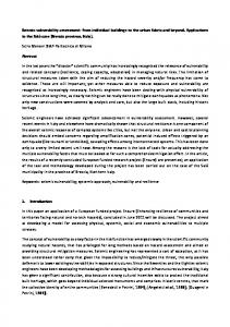
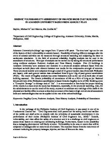
results, but for irregular buildings, torsion requires a complete 3-D nonlinear time-history analysis. Such analysis involves great amount of effort and still perfect results are illusive. A realistic approach to aseismic torsional analysis should include the effect of dynamic magnification of the torsional moments, the effect of simultaneous action of the two horizontal components of the ground motion, and accidental torsion. The accidental torsional moments are intended to account for the possible additional torsion arising from the variation in the relative rigidities, uncertain estimates of dead and live loads, addition of wall panels and partitions after completion of the building, variation of stiffness with time, and inelastic actions. For simplicity, these effects should be accounted for by use of realistic modification factors. The Indian code uses reserve strength of building to meet its well-defined seismic resistant design as done by codes of other countries. Structure going in inelastic zone during string motion but not collapsing is assumed while design. This results in reduction of forces calculated on the basis of elastic structural concepts for design. This is required for the purpose of economy. The ductility ensures safety in case of structure moving in inelastic zone. The main point to ponder is that all the codal provisions are based on the elastic structural response. Hence the relevance to this scenario of current code recommendations, based on elastic response requires investigation and possible modification. The effort is to search a better but practice- oriented simplified approach. In-plan load distribution Failures in buildings during earthquake are often due to inability of its elements to work together in resisting lateral force. This requirement seeks continuity in load transfer system, i.e., seismic load path. A continuous path is necessary for the transmission of lateral force from one part to the other, so that load is transferred back to soil. Horizontal elements or diaphragms that tie the structure together and distribute all the lateral forces distribute lateral forces to vertical members. For buildings having RCC or steel deck as floors, it is assumed that the diaphragm is rigid under the action of the forces in the plane of diaphragm but flexible normal to it. This assumption is acceptable as there is no significant in-plane deformation for the floor. Hence, forces in frame supporting the rigid diaphragm can be distributed by considering rigid body movement of floor slab under seismic action. This is true for symmetric as well as asymmetric structures. In symmetric structures, there will be no rotation. All the frames will have same storey drift. Hence, load will be shared in relation to their stiffness. Asymmetric structures will have translational as well as rotation of the floor. Load sharing will be done accordingly. Since stiffness comes under study, the question regarding determination of its value come next. Reinhorn has carried his study in four stages. The load transfer scheme active during seismic action is essentially a 3-D phenomenon. The seismic action, the resulting inertia force and the structure all are 3-dimensional in nature. Hence it requires 3-D analysis for prediction of the response of building under earthquake. But, in simplified analyses, structural elements parallel to principal direction (frames) are 2-D in character and 2-D analysis is used. Larger the eccentricity between the centre of rigidity and the centre of mass, larger will be the torsional effect. Because of the eccentricity between load and the resistance, floor experiences rotation along with translation. This results in enhanced strength and ductility demand at certain part of the structure. This has been included by considering rigid diaphragm under seismic load. A nonlinear finite element modeling of 4 storey building has been subjected to nonlinear pushover analysis and drift ratio between maximum deformation and average deformation have been found to indicate enhanced seismic demands for six cases starting with no accidental eccentricity to static eccentricity of 0.20 b. The main emphasis of analysis is on deformation capacity. Results are shown in fig 1, fig 2 and table 1.
Six cases for RC MRF building: 1. 1. No accidental eccentricity 2. 2. With accidental eccentricity 3. 3. es/b =0.05 + accidental eccentricity 4. 4. es/b =0.05 + accidental eccentricity 5. 5. es/b =0.05 + accidental
Earthquake load as per IS 1893-2002 Design basis earthquake Maximum considered earthquake Response modification R=3 Response modification R=5
0.014 0.012 0.01 0.008 0.006 0.004 0.002 0
Series1 Series2
1
2
3
4
5
6
Fig 1 Maximum storey drift at Ground storey for the six eccentricity situations at DBE with Series 1(R=5) and Series 2 (R=3)
0.06 0.05 0.04 Series1
0.03
Series2
0.02 0.01 0 1
2
3
4
5
6
Fig 1 Maximum storey drift at roof for the six eccentricity situations at DBE with Series 1(R=5) and Series 2 (R=3)
case1 case2 case3 case4 case5
Storey 1 Storey 2 Storey 3 Storey 4 1 1 1 1 1.05 1.05 1.05 1.05 1.15 1.15 1.15 1.15 1.28 1.29 1.28 1.27 1.37 1.39 1.39 1.37
case6
1.44
1.47
1.47
1.46
Table 1: Drift ratio for all the six cases CONCLUSION In modern constructions we encounter buildings, which exhibit some degree of plan asymmetry. This asymmetry can be caused by an uneven distribution of strength, stiffness and/or mass. In addition, these structures are supposed to be affected by accidental eccentricity. Simplified plane pushover analysis can be used for quick seismic vulnerability assessment for low-rise asymmetric building. Storey drift ratio increases with increase in design eccentricity. Drift ration for different eccentricity gives indication of the enhanced seismic demand on the structure. REFERENCES 1. 2. 3. 4. 5.
6. 7. 8. 9.
Paulay, T. (1997), “Are Existing Seismic Torsion Provisions Achieving the Design Aims?”, Earthquake Spectra, vol. 13, no. 2, 259-279. Moghadam, A.S. & Tso, W.K. (1996), “ Damage Assessment of Eccentric Multistory Buildings using 3-D Pushover Analysis”, Eleventh World Conference on Earthquake Engineering, Mexico Kilar, V. & Fafjar, P. (1997), “Simple Push-Over Analysis of Asymmetric Building”, Earthquake Engineering and Structural Dynamics, Vol.- 26, 233-249. Bertero, R.D. (1995), “Inelastic Torsion For Preliminary Seismic Design”, Journal of Structural Engineering, A.S.C.E., Vol. 121, no. 8, 1183-1189. SeismoSoft (2003) "SeismoStruct - A computer program for static and dynamic nonlinear analysis of framed structures" Chopra A.K. (1995), “Dynamics of Structures: Theory and Applications to Earthquake Engineering”, Prentice-Hall. Annigeri, S. and A.K. Jain (1994), “Torsional Provisions for Asymmetrical Multistory Buildings in IS-1893”, International Journal Of Structures, Vol. 14, No. 2. IS: 1893-2002, “Criteria for Earthquake Resistant Design of Structures”, B.I.S., India. A. K. Sinha, & Dr. P. R. Bose (2002), “Analytical Approach in Seismic Vulnerability Assessment”, 12th Symposium on Earthquake Engineering, Pp. 1307-1316, Vol-II, Dec16-18 2002, IIT, Roorkee.