Author manuscript, published in "International SIGSOFT Symposium on Component-based Software Engineering (CBSE) (2009)"
Selecting Fault Tolerant Styles for Third-Party Components with Model Checking Support Junguo Li, Xiangping Chen, Gang Huang*, Hong Mei, and Franck Chauvel
inria-00459608, version 1 - 24 Feb 2010
Key Laboratory of High Confidence Software Technologies, Ministry of Education, School of Electronics Engineering and Computer Science, Peking University, Beijing, 100871, China {lijg05,chenxp04,huanggang,franck.chauvel}@sei.pku.edu.cn,
[email protected]
Abstract. To build highly available or reliable applications out of unreliable third-party components, some software-implemented fault-tolerant mechanisms are introduced to gracefully deal with failures in the components. In this paper, we address an important issue in the approach: how to select the most suitable fault-tolerant mechanisms for a given application in a specific context. To alleviate the difficulty in the selection, these mechanisms are abstracted as Fault-tolerant styles (FTSs) at first, which helps to achieve required high availability or reliability correctly because the complex interactions among functional parts of software and fault-tolerant mechanism are explicitly modeled. Then the required fault-tolerant capabilities are specified as fault-tolerant properties, and the satisfactions of the required properties for candidate FTSs are verified by model checking. Specifically, we take application-specific constraints into consideration during verification. The satisfied properties and constraints are evidences for the selection. A case study shows the effectiveness of the approach. Keywords: Fault tolerance, model checking, fault-tolerant style, software architecture.
1 Introduction Third-party components, such as COTS (Commercial Off-The-Shelf) components and service components, are commonly used to implement large-scale (often business related) applications, which contributes to their ability to reduce costs and time. These components share some common characters: a) they are produced and consumed by different people. Application developers work as consumers to integrate third-party components into applications, according to interfaces provided by components providers. b) They are reused as black boxes or “gray” boxes. Consumers are unaware of technical details about how such a component is implemented as well as what’s the difference between its updated version and its previous version. *
Corresponding author.
inria-00459608, version 1 - 24 Feb 2010
70
J. Li et al.
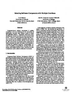
These characters raise a challenge to build highly available or reliable applications out of unreliable components that lack special Fault Tolerance (FT) design1. Most of the existing studies on the topic try to attach fault-tolerant mechanisms (for example, reboot, retry, or replication) to the external of COTS components [11] or services [24] as “wrappers” or “proxies”. They specify such applications at Software Architecture (SA) level because SA is good at modeling interactions among multiple components. The approach works well except that a question is not well answered yet: which faulttolerant mechanism is the most suitable one for a given third-party component in a specific application? The question stems from two facts. On the one hand, the effectiveness of a fault-tolerant mechanism depends on its fitness for an application context, including fault assumption, application domain, system characteristics, etc. [23]. None of the existing mechanisms, such as reboot, recovery blocks and N-Version Programming, are capable of tolerating all faults in all contexts. On the other hand, an anticipated fault characters in a third-party component may change due to its upgrade. So we need to select a suitable mechanism for third-party components during application development or maintenance, taking into consideration the components’ fault assumption, the application’s specific constraints, etc. In the paper, we present a specification and verification-based solution to the problem. The contributions of the paper are two-fold. First, we offer solid evidences to selecting the most suitable fault-tolerant mechanism for a component running in a specific application. The evidences are obtained by model checking and they are necessary to resolve conflicts between continually evolving components and the specificity required by fault-tolerant mechanisms. Once a mechanism cannot successfully recover a fault in an upgraded component, the approach applies to the component again to select another. Second, we take application-specific dependency relationship into consideration in formal specification of an FTSA. This relationship affects the selection and usage of fault-tolerant mechanisms. In the solution, we specify fault-tolerant mechanisms at first, which improve thirdparty components’ availability or reliability, as a special software architectural style, i.e. fault-tolerant styles (FTSs). Then we define semantics of Fault-Tolerant Software g Fault-Tolerant Properties
Applicationಬs Software Architecture
1.1. Specifying fault-tolerant mechanisms as styles 1.2. Specifying fault-tolerant capabilities as properties
Required FaultTolerant Capabilities
Properties Satisfaction List
Verification Model
1. Specifying
1.3. Specifying an application architecture conforming to a fault-tolerant style as an FTSA
[fault-tolerant capabilities are satisfied]
2. Translating
Application-Specific Constraints
3. Model Checking
[fault-tolerant capabilities are not satisfied]
Fig. 1. A process for selecting suitable fault tolerance mechanisms for an component in an application
1
We only discuss software-implemented fault tolerance (SIFT) design in the paper.
inria-00459608, version 1 - 24 Feb 2010
Selecting FTSs for Third-Party Components with Model Checking Support
71
Architectures (FTSAs) conforming to an FTS. The definition supports an applicationspecific constraint (dependency relationships among components), which is seldom considered before. Based on formally specified fault-tolerant properties like fault assumptions, fault-tolerant capability, and application-specific constraints, we verify whether an FTS preserves required properties by model checking. The result determines the suitableness of a mechanism for a specific component in an application. An automatic translation from FTSAs’ behavioral models into model checker’s input (verification model) is also given. Fig. 1 presents an overview of the proposed approach. The remainder of the paper is organized as follows: Section 2 gives an overview of FT and a motivating example of selecting an FTS for an EJB component. Section 3 describes the concept of FTS and FTSA, and how to model FTSs before Section 4 describes how to formalize FTSA, fault-tolerant properties and application-specific constraints. Section 5 focuses on translating the above formalized model into Spin model checker’s input. Section 6 shows how to use the approach to solve the problem in the motivating example. Section 7 clarify some notable points in the approach and discuss the limits of the approach. At last, we give an insight into conclusions and future work in Section 8.
2 Background and a Motivating Example In this section, we give an overview of software-implemented fault tolerance mechanism and a motivating example to clarify the problem solved in the paper. 2.1 Software-Implemented Fault Tolerance Software-implemented fault tolerance is an effective way to achieve high availability and reliability. An activated fault in a component causes errors (i.e. abnormal states that may lead to failures), which is manifested as a failure to its clients. Failures prevent software from providing services or providing correct services for clients [3]. A fault-tolerant mechanism uses a set of software facilities to take two successive steps to tolerate faults: the error detection step aims to identify the presence of an error, while the recovery step aims to transit abnormal states into normal ones (some masking-based fault-tolerant mechanisms do not take the recovery step). The difference among various mechanisms is the way to detect errors and to recover states. Existing fault-tolerant mechanisms are classified as design diversity-based, data diversitybased or environment (temporal) diversity-based mechanisms. Design diversity-based mechanisms require different designs and implementations for one requirement. As a result, even if a failure happened in one version, correct results from other versions can mask it. Data diversity-based mechanisms use data re-expression algorithms to generate a set of similar input data, execute the same operation on those inputs, and use a decision algorithm to determine the resulting output. Environment (temporal) diversity-based mechanisms try to obtain correct results by re-executing failed operations, with different environment configurations. This kind of mechanism is efficient to deal with environment-dependent failure that only happened in a specific execution environment.
72
J. Li et al.
Fault-Tolerant Style (FTS) specifies the structural and behavioral characters of an fault-tolerant mechanism very well. Usually FTSs can be modeled in: a) Box-and-line diagrams and formal (or informal) behavioral descriptions [27]; b) Architectural Description Languages (ADLs) [10, 13, 25]; or c) UML or an UML profile [26, 14]. The latter two are widely used in current practices. We take an UML profile for both SA and FT as the modeling language in the study, but pure ADLs can also be used.
inria-00459608, version 1 - 24 Feb 2010
2.2 A Motivating Example ECperf [9] is an EJB benchmark application, which simulates the process of manufacturing, supply chain management, and order/inventory in business problems. Create-aNew-Order is a typical scenario in ECperf, i.e. a customer lists all products, adds some to a shopping cart, and creates a new order. We use Software Architecture (SA) model to depict the interactions among EJBs in the scenario in Fig. 2. We assume these EJBs are black boxes and we have nothing known about their implementation details. The structural model of ECperf comes from runtime information analysis, with the monitoring support provided by a reflective JEE Application Server (AS) [16].
«NFTUnit» Order
«NFTUnit»
«NFTUnit»
«NFTUnit»
Corp
Util
Mfg
name create
«NFTUnit»
«FTUnit»
name
OrderEnt create create
«NFTUnit» newOrder
«NFTUnit»
client
«NFTUnit»
FBPK
non-fault-tolerant component
create
FBPK
OrderSes
Legend:
fault-tolerant component
«NFTUnit»
OrderLineEnt «NFTUnit»
ItemBmpEJB
«FTFaci»
name name
fault-tolerant facility component connector
«FTInfo»name
conveys-informationto connector
«FTCmd»name
applies-FT-operationto connector
Fig. 2. The part of software architecture of ECperf in the Create-a-New-Order scenario
ECperf cannot tolerate any faults originally, but it needs to be fault tolerable, especially for ItemBmpEJB, which is a frequently used bean-managed persistent EJB in the Create-a-New-Order scenario. There are on average more than 400 invocations for ItemBmpEJB, compared with only one invocation for OrderEnt in the scenario. The availability of ItemBmpEJB may be imperiled by database faults or unreliable connections to databases. These faults are permanent – they do not disappear unless the database or the connections are recovered, unlike transient faults which may disappear in a nondeterministic manner even when no recovery operation is performed. In addition, these faults are activated only under certain circumstances like heavy-load or heavy communication traffic. So the first fault-tolerant requirement is to make ItemBmpEJB capable of tolerating environment-dependent and non-transient (EDNT) faults.
inria-00459608, version 1 - 24 Feb 2010
Selecting FTSs for Third-Party Components with Model Checking Support
73
A common constraint in applications is dependency among components. A component in an application may use other components to fulfill desired functionalities. We call the former a depending component, and the latter a depended-on component and there is a dependency between them [17]. We classify dependencies as weak ones or strong ones: If every time a depending component C1 uses a depended-on component C2, and C1 has to look up or acquire C2 as the first step, there is a weak dependency. On the other hand, if C1 can invoke C2 directly by a reference R that is created during C1’s first initialization, it is a strong dependency. Strong dependency is common because the design improves application’s performance if the invocation happens frequently. With the proliferation of Dependency Injection design in componentbased development, the heavy dependency is more popular. Strong dependencies require a coordinated recovery capability. If C2 failed at some time, the R in C1 is invalid either. Any new invocation for C2 by the R would definitely cause a failure. From the point of view of fault, it is a global error that needs to be recovered coordinately, which is stated in our previous work [17]. Either the R is updated or C1 is recovered when recovering C2. By analyzing runtime information, we find OrderEnt strongly depends on ItemBmpEJB because there is a lookup invocation in OrderEnt when it calls ItemBmpEJB at the first time, and there is not any lookup invocation later when calling ItemBmpEJB again. As a result, both of them should be configured with a fault-tolerant mechanism as a whole. Another application-specific constraint is that ItemBmpEJB’s response time must be within 10 seconds because 10 seconds is long enough for a client waiting for a response. When all fault-tolerant requirements and application-specific constraints are given, the problem is: which fault-tolerant mechanism is the most suitable one for ItemBmpEJB and OrderEnt, without any modifications on their source code? To solve the problem, we describe our approach step by step in the following sections.
3 Modeling Fault-Tolerant Mechanisms as Styles In this section, we specify the structural and behavioral characters in fault-tolerant mechanisms as Fault-Tolerant Styles (FTSs) (Step 1.1 and 1.3 in Fig. 1). By surveying the literature on FT [2, 3], we derive some reusable parts that can be combined to form different FTSs. The well organized FTSs form the foundation of selecting a suitable mechanism for an application. 3.1 The Concept of Fault-Tolerant Styles Although different fault-tolerant mechanisms are distinguished by their structure and interactions with functional components, their primary activities are similar. They control the messages passed in or received from a component, and monitor or control a component’s states. An architectural style is a set of constraints on coordinated architectural elements and relationships among them. The constraints restrict the role and the feature of architectural elements and the allowed relationships among those elements in a SA that conforms to that style [21]. From the point of view of architectural style, entities in a fault-tolerant mechanism are modeled as components, interactions among the entities are be modeled as connectors, and constraints in a mechanisms are modeled as
74
J. Li et al.
Table 1. The stereotype definition for both fault-tolerant components and connectors in FTSA
inria-00459608, version 1 - 24 Feb 2010
UML StereoType Meaning type «FTUnit» Component Components that have fault-tolerant capabilities «NFTUnit» Component Components that have not fault-tolerant capabilities «FTFaci» Component Facility components that enable fault tolerance. By obeying specific structural constraints and coordination, «FTFaci» elements interact with «NFTUnit» elements, to make the latter fault-tolerable. «FTCmd» Connector Changing states «FTInfo» Connector Conveying information
an FTS [18, 26], which is a kind of architectural style. The architecture of a faulttolerant application is a Fault-Tolerant Software Architecture (FTSA), which conforms to an FTS and tolerates a kind(s) of faults. We use a UML profile for both SA and FT [20, 26] and made necessary extensions to specify FTSs and FTSAs (see Table 1), because UML is widely used and easy for communication. There are three kinds of components in the profile: «NFTUnit» components are business components without fault-tolerant capability; «FTUnit» components are business components with fault-tolerant capability either by its internal design or by applying a set of «FTFaci» components to an «NFTUnit» component. We define a stereotype «FTFaci» for well-designed and reliable components, which provide FT services for «NFTUnit»components. There are two kinds of connectors: «FTInfo» connectors are responsible for conveying a component’s states to another; «FTCmd» connectors are responsible for changing an «NFTUnit» component’s states. An «NFTUnit» component and its attached «FTFaci» components, which interact with each other in a specific manner, form a composite «FTUnit» component. Based on the profile, we model fault-tolerant mechanisms as FTSs. Each mechanism’s structure is modeled in UML2.0 component diagram (see Fig. 3 (a)). In order to model the mechanism’s behavior in a similar manner, we use UML2.0 sequence diagram. UML2.0 sequence diagram provides a visual presentation for temporal relations among concerned entities, but its capability to explicitly specify internal states and states transition are limited. So we introduce a special calculation occurrence from the general execution-occurrence definition in UML2.0 sequence diagram. Execution-occurrences are rectangles drawn over lifelines in a sequence diagram, and represent the involvement of components in an interaction or scenario (see Fig. 3 (b)). A calculation occurrence is a special execution-occurrence to define, initialize or change variables in an interaction. The order of different calculation occurrences in a scenario stands for the temporal relations among interactions. Micro-reboot mechanism [7] is an illustrative mechanism to be modeled as FTS. A Micro-reboot style consists of some «FTFaci» components (ExceptionCatcher, Reissuer, and BufferRedirector) and an «FTCmd» Reboot connector for an «NFTUnit» component (Fig. 3). The ExceptionCatcher catches all unexpected exceptions in the «NFTUnit» component. After the caught exceptions are analyzed and the failed component is identified, the failed component is rebooted. Meanwhile, the BufferRedirector blocks incoming requests for the component during recovery. When the failed component is successfully recovered, the BufferRedirector re-issues the blocked requests and the normal process is resumed.
Selecting FTSs for Third-Party Components with Model Checking Support
«NFTUnit»
req
client
«FTFaci»
«FTFaci»
req
Buffer Redirector
«FTFaci»
req
Reissuer
«FTCmd» returnError
«FTCmd»enable
«NFTUnit»
req
Exception Catcher
75
server
«FTInfo» nofifyError
«FTCmd»retry
«FTCmd» reboot
«FTFaci»
FTMgr
(a) The structure of Micro-reboot style «FTFaci»
«NFTUnit» client req
inria-00459608, version 1 - 24 Feb 2010
«FTFaci»
Buffer Redirector
Reissuer req
«FTFaci» ExceptionC atcher
req
«NFTUnit»
FTMgr
server
o2: server.ServFailed =FaultDist()
backup()
o1: Init(client.Failed,bit,0); Init(server.ServFailed,bit,0); Init(server.FType,bit,1) Init(StartTime, getSysTime())
«FTFaci»
req «FTInfo»except notifyError() «FTCmd»enable(true)
analysis()
Calculation Occurences
«FTCmd»reboot
o3: server.ServFailed=Recover() o4: Assert(server.ServerFailed==0)
alt
[correct response]
«FTCmd»retry
success
«FTCmd»enable(false) req
resp o6:Assert(client.Failed==0); EndTime=getSysTime() «FTInfo» except
resp
«FTInfo» except
req resp
resp
«FTInfo» except
«FTCmd» returnError
failed
o5: client.state= global_exception
(b) The behavioral of Micro-reboot style
Fig. 3. The structural (a) and behavior (b) specifications of Micro-reboot style
We also model other FTSs such as Simple Retry style and Retry Blocks style. Simple Retry style is similar to Micro-reboot style except it only re-invokes a failed component again, without rebooting it. Retry Blocks style is similar to Simple Retry style except it uses data re-expression component to mutate inputs before retrying. These FTSs are not shown in the paper due to the space limitations. 3.2 The Classification of Fault-Tolerant Styles We identify some common and key «FTFaci» components and «FTCmd» connectors in Table 2, which can be used for third-party components. They are classified by their
J. Li et al.
functionalities: detecting errors, recovering error states, or smoothing the recovery procedures. A complete FTS consists of an error-detection part, a recovery part, and an auxiliary part (Some FTSs only have two parts or even one part, depending on different FT design principles). Combinations based on the above FT components or connectors form different FTSs. In Fig. 4, seven major FTSs are given by the combination of these entities. These FTSs stands for typical fault-tolerant mechanisms for third-party components. Recovery Blocks and N-Version Programming are design diversity-based mechanisms; N-Copy Programming and Retry Blocks are data diversity-based mechanisms; and Micro-reboot, Simple Retry, and Checkpoint-restart are environment (temporal) diversity-based mechanisms. The identification of common «FTFaci» components and «FTCmd» connectors makes FTSs flexible. A FTS’s error detection part or recovery part can be replaced by another if necessary. For example, Recovery Block style, which works on a primary component and a secondary component implementing same functions, requires an AcceptanceTest to determine whether the primary works correctly or not. But if the primary mainly thrown exceptions when a failure happened, AcceptanceTest is not good at dealing with such abnormal. It can be replaced by ExceptionCatcher, which Table 2. Key modules in fault-tolerant mechanisms Type Component/ Connectors in FTSA «FTFaci» ExceptionCatcher «FTCmd» Watchdog «FTFaci» AcceptanceTest «FTCmd» Reboot
Error Detection Recovery
inria-00459608, version 1 - 24 Feb 2010
76
Explanation
Mechanism examples a Micro-reboot.
Auxiliary
Catches thrown exceptions by component Periodically sends a request to a component to testify its liveness. Decides the correctness of a returned value Resets a failed component’s states by reboot «FTFaci» Set a component’s states, according to StateSetter given parameters. «FTFaci» Switcher Sends a request to a version/instance of a component. «FTFaci» Sends identical requests to multiple DistributerCollector versions/instances of a component, and determines a result by comparing all the returned values. «FTFaci» Slightly modifies an input DataReexpression «FTFaci» Buffers all requests to a failed component BufferRedirector and redirects them when it is recovered «FTCmd» Reissuer Re-sends a request to the target component, after a varied waiting time «FTFaci» FTMgr Coordinates operations between error detector and recovery, or between several recovery operations
Watchdog. Recovery Blocks, Retry Blocks. Micro-reboot. Checkpoint-restart. Recovery Blocks. N-Version Programming (NVP), N-Copy Programming (NCP) Recovery Blocks, NCP. Micro-reboot. Checkpoint-restart. Used in All most all mechanisms.
77
is good at dealing with failures manifested as exceptions. The occasion of a replacement is usually decided by the time when a fault assumption is changed, and the verification of the correctness of the replacement is supported by our model checking approach described in Section 5 if only the correctness is also specified as a property. The combined FTSs would be more plentiful if more «FTFaci» components or «FTCmd» connectors are included. But keep in mind that not all existing fault-tolerant mechanisms are meaningful for third-party components. Because implementation details of these components are hidden from application developers, and components’ internal states are invisible except those accessed through a predefined interface. Most of the mechanisms in the classification can be externally attached to components. A notable example is checkpoint-restart mechanism. Almost all checkpoint-restart protocols require accessing a component’s internal states. Considering an impractical assumption that all components provide an interface to get/set their internal states, checkpoint-restart can only apply to a considerably small number of third-party components that provide state manipulation operations. The similar situation exists in replication mechanism too. Heartbeat Concurrent Detection Error Detection Part
Watchdog Acceptance Test
Preemptive Detection
Switcher Error Handling Fault Tolerance Style
Fault Handling
Recovery Block Style
CheckpointRestart Style
StateSetter Distributer/ Collector
Recovery Part
Simple Retry Style
Exception Catcher
Reconfiguration
N-Version Programming Style N-Copy Programming Style
Micro-reboot Style
inria-00459608, version 1 - 24 Feb 2010
Selecting FTSs for Third-Party Components with Model Checking Support
Retry Block Style
Reinitialize Data Re-expression Buffer/Redirector
Auxiliary Part
FT Manager Reissuer Checkpoint
Fig. 4. The classification of FTSs according to their design principles. We assign the common «FTFaci» components and «FTCmd» connectors to a classification framework give by [3], and we show how to form a FTS by combining some of them.
4 Modeling Fault-Tolerant Properties and Application-Specific Constraints 4.1 Fault-Tolerant Properties and Application-Specific Constraints Given a specific application, a set of requirements on fault-tolerant capabilities, and a set of candidate FTSs, it is critical to select the most suitable one for concerned
78
J. Li et al.
components in the application to meet the requirements. In this section, we abstract both fault-tolerant capability requirements and fault assumptions on components as fault-tolerant properties, and specify application-specific constraints (Step 1.2 in Fig. 1). In the next section, we translate an FTS’s behavioral models in UML sequence diagram, the properties, and the constraints into verification models, and use model checking to verify the FTS’s satisfaction of the properties and the constraints. Table 3. Fault-tolerant properties and application-specific constraints
Fault Assumptions App.– Generic FaultSpecific Tolerant Capabilities Constraints
inria-00459608, version 1 - 24 Feb 2010
Type
Property Name & Description Transient fault assumption (P1): When a component is providing services and a transient fault is activated in it then, its states will be resumed if a fault-tolerant mechanism was applied. Transient faults are nondeterministic and are also called “Heisenbugs”. Environment-dependent and non-transient (EDNT) fault assumption (P2): When a component is providing services and an EDNT fault is activated in it then, its states will be resumed if a fault-tolerant mechanism was applied. EDNT faults are deterministic and activated only on a specific environment. Environment-independent and non-transient fault assumption (EINT) (P3): When a component is providing services and an EINT fault is activated in it then, its states will be resumed if a fault-tolerant mechanism was applied. EINT faults are deterministic and are independent of specific environment. Fault containment (P4): If an error is detected in a component, other components would not be aware the situation. Fault isolation (P5): When a failed component is being recovered, no new incoming requests can invoke the component. Fault propagation (P6): If an un-maskable fault is activated in a component and it cannot be recovered successfully, the client, who issues the request and activates the fault, would receive an error response. Coordinated error recovery (P7): If a global error, which affects more than one component, happened, the error can be recovered. Weak dependency (P8): Component C1 weakly depends on component C2. Strong dependency (P9): Component C3 strongly depends on component C2. Timely constraint (P10): A component always delivers correct response within 10 seconds.
Fault assumption is a kind of important properties. It assumes the characters of faults in a component or an application. Only when an FTS can deal with a certain kind of fault, it is meaningful to discuss the FTS’s other capabilities. Properties P1, P2, and P3 shown in Table 3 denote three fault assumptions. These three properties form a dimension of selecting FTSs. Then fault containment, fault isolation, fault propagation, and recovery coordination are four generic fault-tolerant capabilities. They are shown in Table 3 as P4 to P7 and form another dimension of the selection. P4 stipulates that the source of a failure should be masked, for fear of error propagation. Because not all errors can be masked, property P6 states that if a failed component cannot be recovered, the error should be allowed to propagate to others to trigger a global recovery processes. This is important for some faults that can be tolerated by coordinated recovery among several dependent components. P5 stipulates that new
Selecting FTSs for Third-Party Components with Model Checking Support
79
incoming requests cannot arrive at a failed component. P7 is related to applicationspecific constraints P8 and P9, so it will be explained later. At last, applicationspecific constraints can also affect the selection of suitable FTSs. Properties P8 to P10 describe some application-specific constraints. P8 and P9 stipulate weak and strong dependencies among components, respectively. Property P10 states a performancerelated constraint: a component’s response time must not be more than a certain time in all circumstances. It should be noted that the above fault-tolerant properties only covers some important and typical ones, and they are distilled from a study of FT [3, 2]. Other properties, such as those presented in Yuan et al.’s study [13], can also be appended to the table.
inria-00459608, version 1 - 24 Feb 2010
4.2 Specifying Properties Before formally specifying fault-tolerant properties, we define a base for FTSA. In an FTSA model, components C={c1, c2, …, cn}, where each ci (1 ≤ i ≤ n ) is a «NFTUnit» component. States of an component belong to a states set S={normal, local_error, global_error} and ∀c ∈ C , c.state ∈ S . Local errors are abnormal states that affect only one component and can be resumed by recovering this component individually, whereas global errors may affect more than one component and need to be recovered by coordination of all affected components. Each «NFTUnit» component has a variable Failed to indicate whether the component is failed or not, and ErrorName to indicate the name of an error.
⎧ false , if c.state = normal ∀c ∈ C , c.Failed = ⎨ ⎩true, otherwise The variable ServFailed is an alias of Failed in a component that provides services for others. Each «NFTUnit» component has an Ftype to indicate its fault assumption in a scenario. ∀c ∈ C , c. Ftype ∈ {transient, EDNT, EINT}. For each «NFTUnit» component, it is attached by a fault activation function FaultDist, which specifies faults’ activation occasions and duration in the component decided by Ftype and the given failure-interval distribution. The function may transit a component’s state from normal to local_error or global_error. The above definition only covers FT-related issues. To represent applicationspecific constraints, we classify them as two types because application-specific constraints are various. Generally, if a constraint manifested as “p implies q”, it is treated as fault-tolerant properties, like P10 in Table 3. If a constraint cannot be manifested as “p implies q”, it would be treated as an extra modification of the state transition of FTSA. In our study, we take dependencies as an example of such constraints. It is one of important application-specific constraints in FT. For each c1 and c2 in C, we denote c1 p w c2 if c1 weak dependent on c2, and c1 p s c2 if c1 strong dependent on c2, otherwise, c1 is independent from c2 (i.e. there is no dependent relationships between them). The lifecycle of a component is modeled as a process. The initial trigger of a components’ state transition is a request for its service. A component’s state transition function δ under the constraint of dependent relationship are: if c1 p s c2 ,
80
J. Li et al.
⎧ FaultDist( c1 .Ftype), if c1 .state = normal and c2 .state = normal ⎪ if c .state ! = normal and c .state = normal
δ ( c1 .state) = ⎨c1 .state,
⎪⎩local _ error,
1
2
if c2 .state ! = normal
Otherwise (i.e. c1 p w c2 or c1 is independent from c2), ⎧ FaultDist( c1 .Ftype), if c1 .state = normal otherwise ⎩ c1 .state,
inria-00459608, version 1 - 24 Feb 2010
δ ( c1 .state) = ⎨
An FTS’s recovery part has a Recover function to transit a component’s error state to a normal one. «FTFaci» FTMgr holds a list comp containing components which is configured to be fault tolerable. The components in comp have an extra recovering state, which is visible only by the FTMgr, and a variable to indicate the name of an error. Based on the above definitions, informally expressed fault-tolerant properties and application-specific constraints in Table 3 are formalized as: P1: client.o1.Failed = false ^ server.o2.ServFailed = true ^ server.o2.Ftype = transient ⇒ server.o4.Failed = false P2: client.o1.Failed = false ^ server.o2.ServFailed = true ^ server.o2.Ftype = EDNT ⇒ server.o4.Failed = false P3: client.o1.Failed = false ^ server.o2.ServFailed = true ^ server.o2.Ftype = EINT ⇒ server.o4.Failed = false P4: client.o1.Failed = false ^ server.o2.ServFailed = true ⇒ client.o6.Failed = false P5: client.o1.Failed = false ^ server.o2.ServFailed = true ^ FTmgr.o3.comp[server]. state = recovering ⇒ ∀c ∈ C , c != server, c.ErrorName != FTmgr.o3.comp [server].ErrorName P6: client.o1.Failed = false ^ server.o2.ServFailed = true ^ server.o4.ServFailed = true ⇒ client.o6.Failed = true P7: client.o1.Failed = false ^ server.o2.ServFailed = true ^ server.o2.state = global_error) ⇒ client.o6.Failed = false ^ server.o6.Failed = false. P8: c1 p w c2 P9: c 3 p s c 2 P10: client.o1.Failed = false ^ (server.o2.ServFailed = false V server.o2.ServFailed = true) ⇒ client.o6.EndTime - client.o1.StartTime