Self-Modifying Morphology Experiments with DyRET: Dynamic Robot for Embodied Testing*
arXiv:1803.05629v1 [cs.RO] 15 Mar 2018
Tønnes F. Nygaard1 , Charles P. Martin1 , Jim Torresen1 and Kyrre Glette1 Abstract— Robots need to be able to adapt to complex and dynamic environments for widespread adoption, and adapting the body might yield more flexible and robust robots. Previous work on dynamic robot morphology has focused on simulation, combining simple modules, or switching between locomotion modes. This paper presents an alternative approach: automatic self-reconfiguration of morphology on a four-legged hardware robot. This allows active adaptation of morphology to different environments, and enables rapid tests of morphology with a single robot. In this paper, we report the design of our robot, as well as the results of a study that verifies the performance impact of self-reconfiguration. This study compares three different control and morphology pairs under different levels of servo supply voltage. Experiments were largely performed in the lab, with preliminary tests in an uncontrolled outdoor environment. Our results show that the robot achieves better performance by adapting its morphology, confirming the value of self-reconfiguration in a quadruped robot.
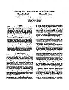
I. INTRODUCTION Legged robots have many advantages over their wheeled counterparts, mainly in their ability to traverse rough terrains. Increasingly, robots are asked to operate in more dynamic and unpredictable environments, alongside other robots, or humans. This move away from the highly-specialized tasks of factory-based industrial robots to new, unknown, scenarios requires robotic systems that can adapt to changing situations. So far, robotic adaptation has focussed on a robot’s control system, but adapting the body of a robot– its morphology–can provide even more flexibility [11]. The concept of embodied cognition suggests that the interaction of the mind, body, and environment can all contribute to the task solving ability of the robotic system [19]. Thus, a self-reconfigurable morphology might allow a robot to adapt its body, as well as control system, to its environment, and the task at hand. Earlier work in evolutionary robotics has also shown that different morphologies are required when operating in environments of varying complexity [1]. A flexibility in the morphology of the robot could be crucial for legged robots to work independently in the field. In this paper, we introduce a practical four-legged robot including self-reconfigurable legs (shown in Fig. 1). We demonstrate the utility of this robot through an experiment showing that changing the leg morphology helps to maintain optimal performance under constrained supply voltage and in challenging environments, both of which would be *This work is partially supported by The Research Council of Norway as a part of the Engineering Predictability with Embodied Cognition (EPEC) project, under grant agreement 240862. 1 Authors are with the Robotics and Intelligent Systems research group, University of Oslo, Norway,
[email protected]
Fig. 1. The robot standing outside during testing. The legs of this robot automatically change length in two places enabling our experiments in selfreconfiguration.
encountered in field applications. Each leg features three rotational joints that are used for locomotion, and two prismatic joints. These prismatic joints are too slow for active use in locomotion, and is therefore used exclusively for changing the morphology of the robot. The robot body can be actively changed during operation to better solve a task, alternatively, the body can be changed between traditional single-morphology experiments to validate solutions on different robots. We present the results of self-reconfiguration tests in the lab, examining how different morphologies with hand-tuned gaits perform when the available torque of the servos is severely reduced by constraining the supply voltage; this could be caused in-the-field by depletion of the robot’s battery. We also describe preliminary tests of the robot under battery power in two potential field environments that support the results of the lab study. There are two contributions of this paper: first, we demonstrate a practical robot design for researching self-modifying morphology that could be adopted by other researchers. Secondly, we show through experimental results–both from the lab, and from potential field scenarios–that having a selfreconfigurable morphology helps a robot maintain optimal performance when adapting to changing supply voltages and environments. These experiments indicate that using selfreconfigurable legs could improve the overall performance of robots doing different tasks in a variety of environments.
II. BACKGROUND Being able to use different modes of locomotion will allow a robot to adapt to the most appropriate way of travel in dynamic and unknown environments. Some robots are able to change their locomotion mode without morphological change [16], while others change their morphology by switching between separate structures, such as wheels and flight rotors [8]. Structures can also be shared by reusing parts of the body for both locomotion modes [4], which saves weight at the expense of mechanical and control complexity. These robots do, however, almost exclusively have a single morphology used for each mode of locomotion, which does not allow a range of different morphologies that can be used to adapt or react to internal or external factors. The field of modular self-reconfigurable robot systems have gone from simple proof-of-concept demonstrations to complex simulations and physical implementations, and can be divided into three architectures [20]. The simplest architecture is the chain or tree architecture, with a serial connection between modules. There are many examples of systems that use this simple architecture, but still manage to show reasonably complex configurations [21]. The lattice architecture has modules connected in parallel along a two or three-dimensional grid. This allows for more advanced base architectures, and connecting sub-parts of the system into meta-modules can yield interesting possibilities when changing the morphology of the system [3]. Other modular robots follow a mobile architecture, and can take on either of the previous architectures, or work as separate units. This is closely related to the field of swarm robotics; physically connecting a swarm of robots to form new, cooperative morphologies can yield very flexible solutions [9]. Despite these advances, modular robots still have a very coarse granularity when it comes to its morphology, when compared to other areas that change a robot’s body. The field of evolutionary robotics uses techniques from evolutionary computation to optimize control and–less often– morphology. Evolution of both control and morphology together is usually performed in simulation and presents additional challenges due to the complex search-space [14]. No physics simulator is completely accurate, and simulators used by robotics researchers are often further simplified to allow quicker and more stable evaluations [10]. The difference between performance in a simulator and a realworld counterpart is referred to as the reality gap, and often makes it very challenging to transfer a result to the real world. A lot of interesting research has been done in simulation alone, but there are many reasons to move more of the research into hardware, as described in one of three grand challenges to the ER field posed by Eiben [5]. There are examples of evolution of morphology in hardware, but these require either excessive human intervention [6], or use slow external reconfiguration of modular systems [18]. There are also examples of self-reconfiguring morphology used exclusively to guide the search for a better controller of a single hand-designed optimal morphology [2]. Our previous
Fig. 2.
Top and side view of the robot.
work demonstrated that the DyRet platform, proposed in this paper, can be used for evolutionary experiments to optimize morphology using mechanical self-reconfiguration [13], the first example of such an approach as far as we are aware. III. S YSTEM OVERVIEW Our robot was developed to be a platform for experiments on self-adaptive morphologies and embodied cognition, and is shown in Fig. 2. It can actively reconfigure its morphology by changing the lengths of the two lower links in its legs, the femur and tibia. The difference is illustrated in Fig. 3. Longer legs mean lower rotational velocity for the servos, at the expense of higher torque requirements. The length of the legs can therefore be used to gear the motors, and allow the robot to change where it sits in the trade-off between movement speed and force surplus continuously. Since it is used with machine learning and evolutionary computation techniques, it must also withstand falls and inefficient or unstable gaits, so maintainability and robustness have been important factors in the design. The design allows it to be easily reproduced or modified by other researchers1 . A. Mechanics The robot applies a mammal-inspired quadruped configuration. All parts can either be bought as inexpensive commercial off-the-shelf components, or can be printed on consumer-grade 3D printers. Since it is used for evolutionary experiments, some parts can also be made in aluminium to ensure a more robust robot, but these can be omitted if the robot is used with more optimal walking gaits. The main body of the robot is constructed with carbon fiber tubing of different diameters, which ensures a stable but low weight base for the four legs. The complete robot weighs 5.5kg, and operates tethered during all experiments. The robot has four legs with five degrees of freedom each, three revolute joints like traditional mammal robots, in addition to two prismatic joints to allow self-modification of the leg lengths. Each leg includes three Dynamixel MX64AT servos, with onboard PID controllers to receive angle 1 The design for our robot–including software, hardware design, and Gazebo-based simulation–has been made available online: http:// robotikk.net/project/dyret/
Coxa
Fe m
ur
Femur length: 185mm to 210mm
i Tib a
Tibia length: 255mm to 355mm
Fig. 3. Diagram of the legs in their rest pose showing the two lengths used in the paper. The shortest available length is to the left, and 80% of available length to the right, as used in our experiments. See Fig. 4 for details on the reconfiguration mechanism in the red dotted square. TABLE I C HARACTERISTICS OF DYNAMIXEL MX-64AT SERVOS [17]. Parameter name No load speed Stall torque Stall power draw Max torque speed
10V 52rpm 5.1Nm 28.6W 21rpm
12V 63rpm 6.0Nm 49.2W 25rpm
14.8V 78rpm 7.3Nm 78.0W 30rpm
commands over USB. The most important characteristics of the servos are summarized in Table I. Off-the-shelf aluminium brackets are used to connect the servos to the rest of the robot where possible, with remaining connections using custom 3D printed and machined aluminium parts. The two lower links of each leg can be reconfigured to different lengths, and the reconfiguration mechanics is shown in Fig. 4. The reconfiguration mechanics use small DC motors connected to lead screws through ANSI-25 stainless steel chain. The leg is connected to the lead screw with a self-lubricating plastic nut, and rides on aluminium rails by two carriages. The length of the leg is sensed by the encoder, which is calibrated on power-up using the mechanical endstop. Since the length of the legs change during operation, care must be taken with all cables running down the leg, and they have been run through cable carriers that keeps the cable runs constant regardless of leg length. Cable lacing techniques has also been used to secure all wires on the robot with minimal strain. The low speed of reconfiguration (≈1mm/s) makes it ineffective to use this mechanism actively during the gait, so they are exclusively used for changing the morphology of the robot.
Fig. 4. The reconfiguration mechanism used in all the legs, with the rest of the leg extending to the right of the image. (1) Brushed DC motor and chain sprocket, (2) Threaded rod and free-spinning sprocket, (3) Nut fixed to the movable part of the leg, (4) Aluminum rails and carriages, (5) Encoders for positioning, (6) Limit switch for zeroing, (7) Cable carrier with the cables for the rest of the leg.
B. Electronics All twelve servos are connected through a common bus to the external computer running the software through a USB serial adapter. Positions of all the servos are reported to the system at approximately 60Hz, and new angle commands are received at the same rate. Temperature, current and load are also read from the servos when any ROS node requests it. This information is used to make sure the servos stay within proper operating specifications. Our system only uses the servos in position mode, by sending and receiving absolute angles, but they can also be controlled by speed or torque directly. We use an Arduino Mega 2560 Rev 3 board for controlling the linear actuators for the self-reconfiguring morphology. A custom PCB shield was designed to allow easy connection, debugging and maintenance of the system, shown in Fig. 5. The custom board has twelve H-bridges to drive the DC motors, limit switches are routed directly to the digital inputs of the microcontroller with internal pull-ups, and all encoders are connected directly to the analog inputs. The h-bridges driving the brushed DC motors are run on PWM from the microcontroller, running a simple proportional controller for each prismatic joint. The microcontroller firmware interfaces through USB serial to the ROS system, and sends positions back to the computer at 10Hz. All actuators retract to their start position when the system starts up to calibrate their zero reference. The accuracy of the linear actuators is limited in practice by the system’s mechanics to approximately 0.5mm. An Xsens MTI-30 attitude and heading reference system (AHRS) is mounted close to the middle of the body to measure linear acceleration, rotational velocity and magnetic fields, giving data on absolute orientation at 100Hz. Reflective markers are mounted on the main body of the robot
Computer Motion capture equipment Experiment manager
Gait evaluator
AHRS / IMU Linear actuators (prismatic joints) Fig. 5. The prototype PCB used to control the linear actuators for mechanical self-reconfiguration of the leg length. The shield plugs into an Arduino Mega below.
to allow motion capture equipment to record the position and orientation of the robot at 100Hz. Previous experiments have also used a LIDAR and depth-camera on the robot, and the robot can carry enough weight to accommodate a full sensor package in the future. Since we are using a ROSbased system with standardized messages and interfaces, other brands or new types of sensors can be integrated into the system without difficulty. C. Software All software functions are implemented as separate Robot Operating System (ROS) nodes in C++, and an overview of the system with its main nodes is shown in Fig 6. An experiment manager node takes input from the user, and runs the different experiments. Trajectories with distance to move, direction, and configuration is sent to a trajectory controller that interfaces to the gait controller. Several different gait controllers can be used, as switching out ROS nodes are simple plug-and-play procedures that can be done during system operation. The gait controller either sends commands to the hardware in the real world, or to the Gazebo simulator [7]. Feedback on performance is received by the gait evaluator from either simulations or the real world, and is analyzed, logged, and reported back to the experiment manager node. D. Control The control of the robot is a separate software module, and can be replaced by different controllers during robot operation. We have successfully implemented and used both high-level and low-level control, and integrating other controller types into the system can be done without difficulty. Only the high-level control is used for experiments with self-reconfiguration, as the gaits produced are more robust and easier to change for an engineer than low-level gaits. Details on the low-level control can be found in our previous work [12]. The high-level control is an inverse-kinematics based position controller for the legs of the robot. It generates a continuous, regular crawl gait, and the body moves at a constant forward speed during the gait sequence, lifting each leg separately to maximize stability. The path for each individual leg is defined by a centripetal Catmull-Rom spline.
Trajectory controller
Gait controller
Servos (rotational joints)
Fig. 6. Overview of the software system. Each named black square is a ROS node, and the system can either be connected to the Gazebo simulator, or to the physical robot and sensors in the real world. All nodes and sensors are interchangeable, as we are using ROS communication with standardized interfaces and message types.
The high-level control makes it easy for an engineer to hand design a gait as well as to intuitively understand gaits that have been optimized by machine learning algorithms. More details can be found in our previous work [13]. IV. E XPERIMENTS AND RESULTS First, we hand designed the gaits to be used in the experiments. The main experiment is done in the lab on our physical test setup for legged robots to test how reducing the supply voltage, and thereby the torque of the motors, affect the performance of two differently sized morphologies. Doing so in the very controlled environment of the lab gives us stable evaluations, and the results are directly transferable to applications where the servos are running directly on unregulated battery power. To what degree the different morphologies impacts performance when faced with different environments gives a good indication if mechanical selfreconfiguration could help adapt to the dynamic environments more and more robots operate in. We take it outside the lab for some preliminary experiments, to see if it is plausible that the results we see in the lab transfers to different potential field environments as well. We evaluate gaits in two different environments, in a covered garage facility, and a more challenging environment outside on an icy walking path while it is snowing. We used two morphologies for our experiments, one that uses the shortest available leg length, and one that uses 80% of the available length. The maximum length of the legs was designed with lab conditions in mind, but we decided on using only 80% of the available length of both links for our experiments, as to not push the robot too hard and allow us to also use it in more challenging environments than the lab. We hand designed two controllers for the two robots, based on experience learned in previous experiments [15], [13].
TABLE II H AND DESIGNED GAIT PARAMETERS
6
Large control 215mm 75mm 50mm 0.35hz 20% 0.0 15mm 10mm
They were further tuned to the two selected morphologies by trial and error in the lab, and were designed to perform as similarly as possible. The speed of the gait is limited to the maximum rotational speed of the servos. The maximum rotational speed is a function of speed and torque, but we have selected a maximum of 25RPM in our current setup, based on the servo specifications and experience from previous experiments. We limited both the frequency of the gait and the length of each step to make sure the gaits were within the acceptable servo rotational speed, but all other gait parameters were kept the same. This means that the larger robot takes longer and slightly faster steps than the smaller robot, and the resulting gait parameters are shown in Table II. A. Lab testing Each morphology was tested with its own hand-designed controller. We also did a control experiment using the small robot control on the large morphology, to make sure that the differences we saw was actually due to the morphology, and not the different controllers. Each gait and morphology pair were evaluated with 1.5m of forward walking, and the same distance backwards. This was repeated ten times for each pair. All three combinations were tested at two different supply voltages, which affects the torque of the joint servos. The results are shown in Fig. 7. At the highest voltage, the large robot performs best with a maximum achieved speed of 5.4m/min, while the small robot has a maximum speed of 3.3m/min. Using the controller from the small morphology on the large robot gives about the same performance as the smaller robot, as expected due to the high-level controller. The Mann-Whitney U test indicated the opposite at lower voltage, with the speed being greater for the smaller robot (Mdn = 2.90) than for the larger robot (Mdn = 2.35), U = 100, p < 0.05. Using the control from the small robot on the large morphology further reduces performance at the lower voltage. B. Field testing The robot was tested in two potential field environments to gain an indication of field performance: a covered garage and an outdoor footpath in winter conditions. In both environments, the robot was powered by an external three-cell LiPo battery pack (11.1V) and controlled from a tethered laptop. The garage had a smooth concrete floor, more slippery than the lab’s carpet, and ambient temperature of around +4◦ C.
4 3 2 1 0
Large robot Small robot Large robot Large robot Small robot Large robot Large control Small control Small control Large control Small control Small control 15V 15V 15V 10V 10V 10V
Fig. 7. Results of the lab testing of the three different controller and morphology pairs at the different supply voltages.
1.2
speed (m/min)
Small control 185mm 75mm 50mm 0.275hz 20% 0.0 15mm 10mm
speed (m/min)
5
Parameter name step length step height step smoothing gait frequency lift duration wag phase wag x amp wag y amp
1.0
0.8
0.6
0.4 Large robot Large control Garage
Small robot Small control Garage
Large robot Small control Garage
Large robot Large control Outside
Small robot Small control Outside
Large robot Small control Outside
Fig. 8. Results of the preliminary field experiments. Note that each garage experiment only has two data points, and the outdoor experiment only three.
The outdoor test was held on a footpath in typical Norwegian winter conditions (around −5◦ C) where the surface was a mix of compacted snow, ice, and gravel – a very challenging environment to retain traction, shown in Fig. 1. Three combinations of morphology and gait were evaluated by 30 seconds of forward walking in each environment. Each evaluation was replicated twice in the garage and three times on the outdoor footpath. The results from the field experiments are shown in Fig. 7. Results from the garage show a big reduction in performance from the lab; the small robot now only achieves a speed of 0.91m/min, and the large robot with the large control achieves a speed of 1.23m/min. The large robot with the control from the small robot does worst of all, at 0.86m/min. On the outdoor footpath, all speeds are further reduced; however, the small morphology with small control now actually outperforms the large robot with large control, and the large robot with small control is still the slowest. Significance of the outdoor footpath results were assessed with the Mann-Whitney U test. This confirmed that the smaller robot’s speed is greater (Mdn = 0.573) than the larger robot with its own control (Mdn = 0.438), U = 9, p < 0.05. When we test the large morphology with the controller from the small robot, it performs slightly better than the large robot with its original controller. Even though it improves in performance, it still does significantly worse than the small robot (U = 9.0, p < 0.05).
V. D ISCUSSION Fig. 7 shows that the large robot suffers a decrease in performance of 56%, when subjected to the lower voltage. The small robot only had a minor reduction in performance from the lower torque, and significantly outperformed the larger robot at the lower voltage. This supports our assertion that the self-adaptive legs can be used to adapt the robot to new voltage by selecting different trade-offs between speed and torque. Using the small controller for the large morphology also resulted in a large reduction in performance, and it had the lowest performance at the reduced voltage. This shows that the morphology is the source of the reduction in performance, not the control. We see a reduced performance for all individuals, when compared to lab conditions, in Fig. 8. A different surface, temperature, control computer, and running on battery are all factors that could have contributed to this. The larger morphology outperformed the smaller morphology in the garage. The experiments outside, however, show that the small robot outperforms the large morphology robot with either controller. This suggests that the trade-off between speed and torque in the smaller robot suits this new and demanding environment better than the large morphology. The fact that the control for the smaller robot worked better for the large morphology than its own controller indicates that the difference in the control between the two robots also contributes to the reduction in performance, though only by about half of the total performance difference. VI. C ONCLUSION AND FUTURE WORK In this paper we introduced a novel four-legged mammalinspired robot with mechanical self-modifying morphology. We demonstrated the utility of self-adaptive morphology by running tests in the lab showing that different servo torques require different morphologies to perform well. We also performed preliminary field testing of the robot in two outdoor environments, which confirmed the results of our lab tests. This indicates that having a mechanically selfmodifying robot may perform better in dynamic or different environments by adapting its morphology as well as control to new conditions. Doing more extensive testing in the field with more evaluations and better tailored test setups would allow investigating optimal morphologies for different environments, and how adaptation of control is related to the morphology of the robot. We tested two different environments, one of which was very challenging for the robot. It would be interesting to test a more extensive collection of environments, and introduce dynamic elements such as other robots or humans that might also affect the efficiency of different morphologycontroller pairs. We also hope that these experiments inspire more research on real world mechanical reconfiguration, and that our newly developed platform might help lower the initial investment needed to begin such research by allowing others to use or extend our robot design.
R EFERENCES [1] Joshua E Auerbach and Josh C Bongard. Environmental influence on the evolution of morphological complexity in machines. PLoS computational biology, 10(1), 2014. [2] Josh Bongard. Morphological change in machines accelerates the evolution of robust behavior. Proceedings of the National Academy of Sciences, 108(4):1234–1239, 2011. [3] David J. Christensen and Kasper Stoy. Selecting a meta-module to shape-change the atron self-reconfigurable robot. In Proceedings IEEE International Conference on Robotics and Automation, May 2006. [4] Ludovic Daler, Julien Lecoeur, Patrizia B. Hahlen, and Dario Floreano. A flying robot with adaptive morphology for multi-modal locomotion. In 2013 IEEE/RSJ International Conference on Intelligent Robots and Systems, pages 1361–1366, Nov 2013. [5] Agoston E. Eiben. Grand challenges for evolutionary robotics. Frontiers in Robotics and AI, 1:4, 2014. [6] Milan Jelisavcic, Matteo de Carlo, Elte Hupkes, Panagiotis Eustratiadis, Jakub Orlowski, Evert Haasdijk, Joshua E. Auerbach, and Agoston E. Eiben. Real-world evolution of robot morphologies: A proof of concept. Artificial Life, 23(2):206–235, 2017. [7] Nathan Koenig and Andrew Howard. Design and use paradigms for gazebo, an open-source multi-robot simulator. In 2004 IEEE/RSJ International Conference on Intelligent Robots and Systems (IROS), volume 3, pages 2149–2154 vol.3, Sept 2004. [8] Alex Kossett, Ruben D’Sa, Jesse Purvey, and Nikolaos Papanikolopoulos. Design of an improved land/air miniature robot. In 2010 IEEE International Conference on Robotics and Automation, May 2010. [9] Francesco Mondada, Andr Guignard, Michael Bonani, Daniel Bar, Michel Lauria, and Dario Floreano. Swarm-bot: from concept to implementation. In Proceedings 2003 IEEE/RSJ International Conference on Intelligent Robots and Systems, Oct 2003. [10] Jean-Baptiste Mouret and Konstantinos Chatzilygeroudis. 20 years of reality gap: a few thoughts about simulators in evolutionary robotics. In Proceedings of the Genetic and Evolutionary Computation Conference Companion, pages 1121–1124. ACM, 2017. [11] Satoshi Murata and Haruhisa Kurokawa. Self-reconfigurable robots. IEEE Robotics Automation Magazine, 14(1):71–78, March 2007. [12] Jørgen Nordmoen, Kai Olav Ellefsen, and Kyrre Glette. Combining map-elites and incremental evolution to generate gaits for a mammalian quadruped robot. In Applications of Evolutionary Computation. Springer, 2018. To appear. [13] Tønnes F. Nygaard, Charles P. Martin, Eivind Samuelsen, Jim Torresen, and Kyrre Glette. Real-world evolution adapts robot morphology and control to hardware limitations. 2018. preprint:http://folk.uio.no/charlepm/preprints/ 2018-RealWorldAdaptation.pdf. [14] Tønnes F. Nygaard, Eivind Samuelsen, and Kyrre Glette. Overcoming initial convergence in multi-objective evolution of robot control and morphology using a two-phase approach. In Giovanni Squillero and Kevin Sim, editors, Applications of Evolutionary Computation, pages 825–836. Springer International Publishing, 2017. [15] Tønnes F. Nygaard, Jim Torresen, and Kyrre Glette. Multi-objective evolution of fast and stable gaits on a physical quadruped robotic platform. In 2016 IEEE Symposium Series on Computational Intelligence (SSCI), pages 1–8, 2016. [16] Kevin Peterson and Ronald S. Fearing. Experimental dynamics of wing assisted running for a bipedal ornithopter. In IEEE/RSJ International Conference on Intelligent Robots and Systems, 2011. [17] ROBOTIS. MX-64AT e-Manual v1.31.30. Robotis Ltd., 2018. [18] Vuk Vujovic, Andre Rosendo, Luzius Brodbeck, and Fumiya Iida. Evolutionary developmental robotics: Improving morphology and control of physical robots. Artificial Life, 2017. [19] Andrew Wilson and Sabrina Golonka. Embodied cognition is not what you think it is. Frontiers in Psychology, 4:58, 2013. [20] Mark Yim, Wei min Shen, Behnam Salemi, Daniela Rus, Mark Moll, Hod Lipson, Eric Klavins, and Gregory S. Chirikjian. Modular selfreconfigurable robot systems [grand challenges of robotics]. IEEE Robotics Automation Magazine, 14(1):43–52, March 2007. [21] Victor Zykov, W Phelps, Nicolas Lassabe, and Hod Lipson. Molecubes extended: Diversifying capabilities of open-source modular robotics. In IROS-2008 Self-Reconfigurable Robotics Workshop, pages 22–26, 2008.