Self-TUNe-ing of a J2EE clustered application O. Chebaro
L. Broto
J.-P. Bahsoun
D. Hagimont
Toulouse University IRIT Laboratory 118 Route de Narbonne F-31062 TOULOUSE CEDEX 9
[email protected] Abstract The Java 2 Platform, Enterprise Edition (J2EE) defines a model for developing multi-tier distributed applications, such as e-commerce applications. Such applications are typically composed of a web server, a servlet server, optionally an EJB server and a database server. Clusters allow replication of each tier instance, thus providing an appropriate infrastructure for high availability and scalability. However, such applications are complex to administrate and often lack deployment and reconfiguration tools. Moreover, the fact that management tasks are performed by humans leads to many configuration errors and low reactivity. To address this issue, we designed and implemented an autonomic management system which provides an environment for deploying and autonomously reconfiguring distributed applications as required. The main principle is to wrap legacy software pieces in components in order to administrate a software infrastructure as a component architecture. Several languages (textual, graphical) are introduced to describe deployment and reconfiguration policies. This paper presents an overview of the TUNe autonomic management system and focuses on its application to the management of a clustered J2EE application.
1. Introduction J2EE architectures are as a convenient way to build efficient ecommerce web applications. To address availability and scalability issues, this multi-tiers model can benefit from clustering techniques that allow, by means of replication and consistency mechanisms, to tolerate failures and increase application capacities. However, J2EE applications (the whole infrastructure including the middleware runtimes) are not easy to manage. Their deployment process (installation and configuration) is as complex as tricky, no execution monitoring mechanism
really exists and dynamic reconfiguration remains a goal to achieve. This lack of manageability makes it very difficult to take full advantage of clustering capabilities, i.e. expanding/collapsing replicas sets as needed, and so on A very promising approach to this issue is to implement administration as an autonomic software. Such software can be used to deploy and configure applications in a distributed environment. It can also monitor the environment and react to events such as failures or overloads and reconfigure applications accordingly and autonomously. This paper reports on an ongoing project that aims at providing system administrators with a management environment that is as automated as possible. This management system called TUNe (Toulouse University Network) targets a wide range of applications, especially existing (legacy) applications. In this paper, we report on our experience in using TUNe for the deployment (installation/configuration) and reconfiguration of a clustered J2EE application. We show how TUNe allows deploying an infrastructure of servers such as Apache, Tomcat and Mysql, and a real benchmark application called RUBIS. The rest of this paper is structured as follows. Section 2 overviews clustered J2EE applications and their life cycle and presents the issues related to deployment, configuration and more generally management. Then, Section 3 presents TUNe, a contribution to ease such applications management by providing automatic deployment and configuration tools. Section 4 presents our experiments with J2EE and an experimental evaluation. After a review of related works in Section 5, Section 6 concludes and presents future work.
2. Administration of J2EE clusters This introductory section overviews clustered J2EE applications and their life cycle before presenting the associated management issues.
2.1. Clustered J2EE Applications and their Lifecycle J2EE applications [9] are usually composed of four different tiers, either running on a single machine or on up to four ones: • A web server (e.g. Apache [13]), that manages incoming client requests and, depending if those relate to static or dynamic content, serves them or routes them to the presentation tier (the servlet container) using an appropriate protocol (e.g. AJP13 for Tomcat). • A servlet container (e.g. Tomcat [12]), that receives forwarded requests from the web tier, interacts with the EJB container for invoking business code and fetching results, and generates a web document presenting the results to the end-user. database storing application data by sending SQL requests by the way of the JDBC framework and dynamically
Figure 1. Architecture of dynamic web applications
Database clustering solutions often remain commercial, like Oracle RAC (Real Application Cluster) or DB2 cluster and require using a set of homogeneous full replicas. We can however cite C-JDBC [4], an open source JDBC clustering middleware that allows using heterogeneous partial replicas providing with consistency, caching and load balancing. J2EE applications life cycle consists in three main steps as illustrated in Figure 2. These steps are detailed below: deployment, monitoring and reconfiguration.
• An EJB container (e.g. Jonas [14]), that hosts Enterprise Java Beans which include the business code of the application. The invoked EJBs may have to be loaded/stored from the database by sending SQL requests through JDBC. • A database management system (e.g. MySQL server [10]), that manages the application’s persistent data. The main motivations for clustering are scalability and fault tolerance. Scalability is a key issue in case of web applications that must serve billion requests a day. Faulttolerance does not necessarily apply to all sites, but to applications where information delivery is critical (as commercial web sites for example). Both scalability and faulttolerance are offered through replication (and consistency management). In the case of J2EE applications, replication at the level of each tier provides applications with service availability when machine failures occur, as well as efficiency by load balancing incoming requests between replicas. The architecture of clustered J2EE applications is depicted in Figure 1 and detailed below in the case of an Apache, Tomcat and MySQL clusters. Apache clustering is managed through HTTP load balancing mechanisms that can involve hardware and/or software balancers. Tomcat clustering is made by using the load balancing feature of Apache’s mod jk plugin. Each mod jk can be configured in order to balance requests on all or on a subset of Tomcat instances, according to a weighted round-robin policy.
Figure 2. J2EE Applications Life Cycle • Deployment. At the deployment step, tiers must firstly be installed on hosts and be configured to be correctly bound to each other. Then, application logic and data can be initialized. Application tiers are often delivered through installable packages (e.g. RPMs) and the configuration is statically expressed in configuration files which map components to resources. • Monitoring. Once the application has been deployed on the J2EE cluster, one needs to know both the system and the application states to be aware of problems that may arise. Most common issues are due either to hardware faults such as a node or network link failure, or inappropriate resource usage when a node or a tier of the application server becomes a bottleneck.
• Reconfiguration. Once a decision has been taken (e.g., extension of a J2EE tier on new nodes to handle increased load), one must be able to perform appropriate reconfiguration, dynamically and avoiding as far as possible to stop the application.
2.2. Challenges Currently, no integrated deployment environment exists for clustered J2EE applications. Each tier must be installed manually and independently. The whole assembly, including clustering middleware, must be configured manually mainly through static configuration files (and also there isnt any configuration consistency verification). Consequently, the deployment and configuration process is a complex task to perform. J2EE cluster monitoring is also a weakly covered aspect. It is obviously possible to see hosts load or to track failures using SNMP, but this is not enough to get accurate information about application components. In terms of reconfiguration, no dynamic mechanism is really offered. Only the Apache server enables to dynamically take into account configuration file changes, others tiers need to be stopped and restarted in order to apply modifications. In this context, in order to alleviate the burden of application administrator, to take advantage of clustering and thus to be able to optimize performance and resource consumption, there is a crucial need for a set of tools: • an automated deployment and configuration tool, that allows to easily and user-friendly deploy and configure an entire clustered J2EE application, • an efficient application monitoring service that automatically gathers, filters, and notifies events that are pertinent to the administrator, • a framework for dynamic reconfiguration. These challenges are addressed by TUNe as described in the next section.
3. TUNE Since TUNe addresses the management of very heterogeneous software, our key design choice was to rely on a component model to provide a uniform management interface for any managed resource. Therefore, each legacy software is wrapped in a component which interfaces its administration procedures. We refer to the approach as the component-based management approach.
3.1. Component-Based Management Component-based management aims at providing a uniform view of a software environment composed of different types of servers. Each managed server is encapsulated in a component and the software environment is abstracted as a component architecture. Therefore, deploying, configuring and reconfiguring the software environment is achieved by using the tools associated with the used component-based middleware. The component model we use in TUNe is Fractal [3], a reflective component model intended for the construction of dynamically configurable and monitored systems. A Fractal component is a run-time entity that is encapsulated and communicates with its environment through well-defined access points called interfaces. Fractal components communicate through explicit bindings. A binding corresponds to a communication path between two or more components. These binded components can form a component architecture. The Fractal specification specifies several useful controllers: the binding controller allows creating or removing bindings between components; the life-cycle controller allows starting and stopping the component; the attribute controller allows setting and getting configuration attributes. Finally, Fractal provides a rich set of control interfaces for introspecting (observing) and reconfiguring a deployed architecture. In Fractal, the architecture of an application is described using an Architecture Description Language (ADL). This description is an XML document which details the architectural structure of the application to deploy, e.g. which software resources compose the application, how many servers and/or replicas are created, how are the servers bound together, etc ... However, we observed that directly relying on a component model for system administration has several drawbacks: • wrapping components are difficult to implement. I requires to have a good understanding of the used component model (Fractal), • deployment is not very easy. ADLs are generally very verbose and still require a good understanding of the underlying component model. Moreover, if we consider large scale software infrastructure such as those deployed over a grid (another application domain addressed by TUNe), deploying a thousand of servers requires an ADL deployment description file of several thousands of lines, • autonomic managers (reconfiguration policies) are difficult to implement as they have to be programmed using the control interfaces of the component model.
This also required a strong expertise regarding the used component model. This led us to the conclusion that a higher level interface was required for describing the encapsulation of software in components, the deployment of a software environment potentially in large scale and the reconfiguration policies to be applied autonomically. We present our proposal in the next section.
3.2. TUNes Management Interface As previously mentioned, our main target is to make administrators life easier. So we want to provide a high level interface for the description of the application to wrap, deploy and reconfigure by hiding the details of the component model we rely on and providing a more intuitive policy specification interface for wrapping, deployment and reconfiguration. This led us to the following design choices: • Regarding wrapping, our approach is to introduce a Wrapping Description Language which is used to specify the behavior of wrappers. A WDL specification is interpreted by a generic wrapper Fractal component, the specification and the interpreter implementing an equivalent wrapper. Therefore, an administrator doesn’t have to program any implementation of Fractal component. • Regarding deployment, our approach is to introduce a UML profile for graphically describing deployment schemas. First, a UML based graphical description of such a schema is much more intuitive than an ADL specification, as it doesnt require expertise of the underlying component model. Second, the introduced deployment schema is more abstract than the previous ADL specification, as it describes the general organization of the deployment (types of software to deploy, interconnection pattern) in intension, instead of describing in extension all the software instances that have to be deployed. • Regarding reconfiguration, our approach is to introduce a UML profile for the description of state diagrams. These state diagrams are used to define workflows of operations that have to be performed for reconfiguring the managed environment. One of the main advantages of this approach, besides simplicity, is that state diagrams manipulate the entities described in the deployment schema and reconfigurations can only produce an (concrete) architecture which conforms to the abstract schema, thus enforcing reconfiguration correctness. These three aspects are detailed in the next section through our experiments with J2EE.
4. Using TUNe for J2EE The autonomic management policies considered in this paper are self-optimization and self-repair.
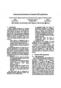
4.1. Deployment The UML profile we introduce for specifying deployment schemas is illustrated in Figure 3 where a deployment schema is defined for a J2EE cluster. A deployment schema describes the overall organization of a software infrastructure to be deployed. At deployment time, the schema is interpreted to deploy component architecture. Each element (the boxes) corresponds to a software which can be instantiated in several component replicas. A link between two elements generates bindings between the components instantiated from these elements. Each binding between two components is bi-directional (actually implemented by 2 bindings in opposite directions), which allows navigation in the component architecture. An element includes a set of configuration attributes for the software. Most of these attributes are specific to the software, but few attributes are predefined by TUNe and used for deployment: • wrapper is an attribute which gives the name of the WDL description of the wrapper, • legacyFile is an attribute which gives the archive which contains the legacy software binaries and configuration files, • hostFamily is an attribute which gives a hint regarding the dynamic allocation of the nodes where the software should be deployed, • initial is an attribute which gives the number of instances which should be deployed. The default value is 1. The schema Figure 3 (left side) describes a J2EE cluster containing one Apache, two Tomcats, one C-JDBC and two Mysql that should be deployed. A probe is linked with Tomcat, which monitors the server in order to trigger a repair / reconfigure procedure. In this schema, the initial attribute of each element gives the number of replicas to be initially instantiated. A cardinality is associated with each link, which gives the minimal and maximal number of binding between elements. The cardinality is taken into account, both at deployment and reconfiguration time. In Figure 3 (right side) we see the component architecture actually instanciated from this schema. The lines represent relationships (or bindings) between components. Apache (web server) balances the requests between two replicated tomcats (servlet engines). The Tomcat servers
implemented in Java. The main motivations for the introduction of WDL are: • to hide the complexity of the underlying component model (Fractal), as the administrator doesn’t have to immplement wrappers as Fractal components. • that most of the needs should be met with a finite set of generic methods that can be therefore reused.
Figure 3. Deployment Schema and Management Layer for J2EE Cluster
are both connected to the C-JDBC database clustering middleware. This latter is connected to two MySQL database servers.
4.2. A Wrapping Description Language Upon deployment, the above schema is parsed and for each element, a number of Fractal components are created. These Fractal components implement the wrappers for the deployed software, which provide control over the software. Each wrapper Fractal component is an instance of a generic wrapper which is actually an interpreter of a WDL specification. A WDL description defines a set of methods that can be invoked to configure or reconfigure the wrapped software. The workflow of methods that have to be invoked in order to configure and reconfigure the overall software environment is defined thanks to an interface introduced in Section 4.3. Generally, a WDL specification provides start and stop operations for controlling the activity of the software, and a configure operation to reflect the values of the attributes (defined in the UML deployment schema) in the configuration files of the software. Notice that the values of these attributes can be modified dynamically. Other operations can be defined according to the specific management requirements of the wrapped software, these methods being
Figure 4. Apache WDL specification Figure 4 shows an example of WDL specification which wraps an Apache server. It defines start and stop methods which can be invoked to launch/stop the deployed Apache server, and a configure method which reflects configuration attributes in the configuration file of the Apache server, and an addWorkers method that adds the list of Tomcats to the Apache workers file (which configures the load-balancer). Most of the Java implementations of these methods are generic and have been used in the wrappers of most of the software we wrapped (currently we have 2 implementations of configuration methods: one for XML configuration files like Tomcat configuration file, and another for plain text files like Apache configuration file). A method definition includes the description of the parameters that should
be passed when the method is invoked. These parameters may be String constants, attribute values or combination of both (String expressions). All the attributes defined in the deployment schema can be used to pass the configured attributes as parameters of the method invocations. However, several additional attributes are automatically added and managed by Tune: • dirLocal is the directory where the software is actually deployed on the target machine, • compName is a unique name associated with the deployed component instance, In Figure 4, the start method takes as parameters the shell command that launch the server, and the environment variables that should be set: • $dirLocal/apache/bin/apachectl is the name of the binary to be executed for starting or stopping the Apache server, • LD LIBRARY PATH=$dirLocal is an envionment variable to pass to the binary. The configure method is implemented by the ConfigurePlainText Java class. This configuration method generates a configuration file composed of pairs: • $dirLocal/apache/conf/httpd.conf is the name of the configuration file to generate, • ” ” is the separator between each attribute and value,
probes in the deployment schema) or by a wrapped legacy software which already includes its own monitoring functions. Whenever a wrapper component is instantiated, a communication pipe is created (typically a UNIX pipe) that can be used by the wrapped legacy software to generate an event, following a specified syntax which allows for parameter passing. Notice that the use of pipes allows any software (implemented in any language environment such as Java or C++) to generate events. An event generated in the pipe associated with the wrapper is transmitted to the administration node where it can trigger the execution of reconfiguration programs (in our current prototype, the administration code, which initiates deployment and reconfiguration, is executed on one administration node, while the administrated software is managed on distributed hosts). An event is defined as an event type, the name of the component which generated the event and eventually an argument (all of type String). For the definition of reactions to events, we introduced a UML profile which allows specifying reconfiguration as state diagrams. Such a state diagram defines the workflow of operations that must be applied in reaction to an event. An operation in a state diagram can assign an attribute or a set of attributes of components, or invokes a method or a set of methods of components. To designate the components on which the operations should be performed, the syntax of the operations in the state diagrams allows navigation in the component architecture, similarly to the wrapping language.
• and the attributes and value are separated by a ”:” character. It is sometimes necessary to navigate in the deployed component architecture to access key attributes of the components in order to configure the software. For instance, the configuration of an apache server requires knowing the name and location of the Tomcat servers it is bound to. Therefore, in the Apache wrapper (Figure 4), we need to access Tomcats parameters in order to get their hosts and ports variables. Since in the deployment schema there is a link between the Apache and Tomcat elements, there are bindings between the Apache and the Tomcats at the component level. These bindings allow navigating in the management layer. In the example in the addWorkers method, $tomcat.nodeName returns the list of names of the nodes where Tomcat servers are deployed.
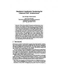
Figure 5. State diagrams for repair For example, let’s consider the diagram in Figure 5 which is the reaction to a Tomcat failure. The event fixTomcat is generated by a probeTomcat component instance; therefore the variable this is the name of this probeTomcat component instance. Then: • this.stop will invoke the stop method on the probing component (to prevent the generation of multiple events),
4.3. A UML profile for (re)configuration procedures
• this.tomcat.start will invoke the start method on the Tomcat component instance which is linked with the probe. This is the actual repair of the faulting Tomcat server,
Reconfigurations are triggered by events. An event can be generated by a specific monitoring component (e.g.
• this.start will restart the probe associated with the Tomcat.
Notice that state diagram’s operations are expressed using the elements defined in the deployment schema, and are applied on the actually deployed component architecture.
4.4.1
Self-Repair
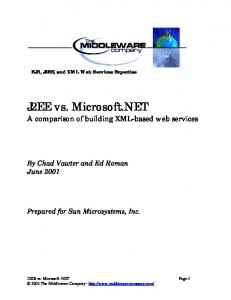
In this experiment, we used TUNe to deploy a J2EE architecture composed of one Apache, two Tomcats, one CJDBC and two MySQLs. The main objective of this experiment is to demonstrate the effectiveness of automatic repair in the case of server failure. Consequently, we artificially induced the crash of a Tomcat server in the managed system and we observed the load distribution (the CPU usage) on the different servers.
Figure 7. Self-Repair with TUNe
Figure 6. State diagrams for start A similar diagram is used to start the deployed J2EE cluster, as illustrated in Figure 6. In this diagram, when an expression starts with the name of an element in the deployment schema (apache or tomcat ...), the semantic is to consider all the instances of the element, which may result in multiple method invocations. The starting diagram ensures that (1) configuration files must be generated, and then (2) the servers must be started following the order. Similar diagrams can be drawn to define the actions or methods that should be invoked while upsizing or downsizing a component in reaction to events of load peak.
Figure 7 shows the observed behavior. During the interval between the crash and the repair, the CPU usage of Tomcat1 increases rapidly since the workload is sent to the single remaining server, but only for a short time interval(about 2 seconds), as TUNe detects the failure and repairs it. Rapidly, the two Tomcats stabilize at the same CPU usage level as before the crash. 4.4.2
Self-Optimization
In this experiment, we illustrate the dynamic allocation and deallocation of nodes to tackle performance issues related to a changing workload: at the beginning of the experiment, the managed system is submitted a medium workload then the load increases progressively until the CPU usages reaches the limit configured in the probe (40%).
4.4. Experimental evaluation We evaluated our prototype in a J2EE cluster running RUBiS [1], a standard benchmark modeled according to an online auction service such as eBay. RUBiS provides a load injector to emulate clients. Experiments ran in the Grid 5000 [6] environment (a national grid infrastructure). The J2EE cluster described in the previous section has been implemented and TUNe was used to deploy and administrate it. The evaluations reported in this paper focus on self-optimization for and self-repair for the web container tier (Tomcat).
Figure 8. UpSize with TUNe Figure 8 shows the observed behavior. After reaching the 40% of average CPU load, a new Tomcat is deployed on
a new node to handle the load increase. Subsequently the average CPU load decreases as the load is balanced on both Tomcats which stabilize at the same CPU usage level.
We demonstrated the benefits of using TUNe for the autonomic administration of a clustered J2EE application.
6. Conclusions
Figure 9. DownSize with TUNe Then we decrease progressively the submitted workload until the average CPU load decreases below the limit configured for the downsize in the probe (20%). Figure 9 shows the observed behavior. After decreasing below 20% of average CPU load, one of the two deployed Tomcats is undeployed and the other serves all the traffic.
5. Related Work Autonomic computing is an appealing approach that aims at simplifying the hard task of system management, thus building self-healing, self-tuning, and self-configuring systems [8]. Management solutions for legacy systems are usually proposed as ad-hoc solutions that are tied to particular legacy system implementations (e.g. [15] for self-tuning cluster environments). This unfortunately reduces reusability and requires autonomic management procedures to be reimplemented each time a legacy system is taken into account in a particular context. Moreover, the architecture of managed systems is often very complex (e.g. multi-tier architectures), which requires advanced support for its management. Relying on a component model for managing legacy software infrastructure has been proposed by several projects [2], [5], [7], [11] and has proved to be a very convenient approach, but in most of the cases, the autonomic policies have to be programmed using the programming interface of the underlying component model (a framework for implementing wrappers, configuration APIs or deployment ADLs) which is too low level and still error prone. In this paper, we proposed a high level interface which is composed of a language/framework for the description of wrappers: • a UML profile for specifying deployment schemas, • a UML profile for specifying reconfigurations as state transition charts.
As the popularity of dynamic-content Web sites increases rapidly, there is a need for maintainable, reliable and above all scalable platforms to host these sites. Clustered J2EE servers is a common solution used to provided reliability and performances. J2EE clusters may consist of several thousands of nodes, they are large and complex distributed system and they are challenging to administer and to deploy. Hence is a crucial need for tools that ease the administration and the deployment of these distributed systems. Our ultimate goal is to simplify the hard task of system management. In this paper, we propose a higher level interface for describing the encapsulation of software in components, the deployment of a software environment and the reconfiguration policies to be applied autonomically. This management interface is mainly based on UML profiles for the description of deployment schemas and the description of reconfiguration state diagrams. A tool for the description of wrapper is also introduced to hide the details of the underlying component model.
References [1] C. Amza, E. Cecchet, A. Chanda, A. Cox, S. Elnikety, R. Gil, J. Marguerite, K. Rajamani, and W. Zwaenepoel. Specification and Implementation of Dynamic Web Site Benchmarks. In IEEE 5th Annual Workshop on Workload Characterization, Austin, TX, 2002. [2] G. Blair, G. Coulson, L. Blair, H. Duran-Limon, P. Grace, R. Moreira, and N. Parlavantzas. Reflection, self-awareness and sef-healing in openorb. In 1st Workshop on Self-Healing Systems, WOSS 2002, 2002. [3] E. Bruneton, T. Coupaye, and J. B. Stefani. Recursive and Dynamic Software Composition with Sharing. In International Workshop on Component-Oriented Programming, Malaga, Spain, June 2002. http://fractal.objectweb.org. [4] E. Cecchet, J. Marguerite, and W. Zwaenepoel. C-JDBC: Flexible Database Clustering Middleware. In USENIX Annual Technical Conference, Freenix track, Boston, MA, 2004. http://c-jdbc.objectweb.org/. [5] D. Garlan, S. Cheng, A. Huang, B. Schmerl, and P. Steenkiste. Rainbow: Architecture-based self adaptation with reusable infrastructure. In IEEE Computer, 37(10), 2004. [6] Grid 5000. Grid 5000 Web Site. https://www.grid5000.fr. [7] D. Hagimont, S. Bouchenak, N. D. Palma, and C. Taton. Autonomic management of clustered applications. In IEEE International Conference on Cluster Computing, 2006. [8] J. O. Kephart and D. M. Chess. The vision of autonomic computing. In IEEE Computer Magazine, 36(1), 2003.
[9] S. Microsystems. Java 2 platform enterprise edition (j2ee). [10] MySQL. MySQL Web Site. http://www.mysql.com/. [11] P. Oriezy, M. Gorlick, R. Taylor, G. Johnson, N. Medvidovic, A. Quilici, D. Rosenblum, and A.Wolf. An architecture-based approach to self-adaptive software. In IEEE Intelligent Systems 14(3), 1999. [12] The Apache Software Foundation. Apache Tomcat. http://tomcat.apache.org/. [13] The Apache Software Foundation. HTTP server project. http://httpd.apache.org/. [14] The ObjectWeb Consortium. Jonas Java Open Application Server. http://jonas.objectweb.org. [15] B. Urgaonkar, P. Shenoy, A. Chandra, and P. Goyal. Dynamic Provisiong of Multi-Tier Internet Applications. In 2nd International Conference on Autonomic Computing, Seattle, WA, 2005.