Sensor and Actuator Fault Isolation Using Parameter Interval based Method for Nonlinear Dynamic Systems Zetao Li 1 , Boutaieb Dahhou 2,3 , Gilles Roux 2,3 , Jing Yang 1 , and Cuixia Zhang 4 1
Electrical Engineering College, Guizhou University, Guiyang, Guizhou, 550003, China
[email protected] [email protected] 2 Universit´e de Toulouse; UPS, INSA, INP, ISAE; F-31077 Toulouse, France 3
4
CNRS; LAAS; 7 Avenue du Colonel Roche, F-31077 Toulouse, France
[email protected] [email protected] Electronical and Electrical Engineering Department, Suzhou University, Suzhou, Anhui, 234000, China
[email protected]
ABSTRACT Fault isolation problem for sensor and actuator in nonlinear dynamic systems is studied. Parameter interval based fault isolation method has fast isolation speed and fits many kinds of nonlinear dynamic systems. This method is extended to the isolation of sensor fault and actuator fault. The example shows good performance.
1 INTRODUCTION Fault detection and isolation (FDI) problem for nonlinear dynamic systems has received more and more attentions recently. The significant results mainly belong to three kinds of methods: The method based on nonlinear geometrical theory (1; 2; 3), based on parity space theory (4; 5) and based on adaptive observers (6; 7). The application of the first one is limited because there is not always suitable framework of decoupling for a general nonlinear dynamic system. The method based on parity space theory has only been studied for some special systems. The speed of adaptive observers based method is not ideal due the parameter identification which lasts a long time. In our previous work, we have put forward a parameter interval based method for nonlinear dynamic systems with respect to the faults of the dynamic part of the system (8; 9; 10). This method fits many kinds of nonlinear dynamic systems, its isolation speed is fast. In this paper, this method is extended to sensor and actuator fault isolation problems for nonlinear dynamic systems. The example shows good performance of this method for sensor and actuator fault isolations for nonlinear dynamic systems. 2
PARAMETER INTERVAL BASED FAULT ISOLATION METHOD In the parameter interval based method, the practical range of each parameter is divided into a certain number of intervals. After occurrence of a fault, the value of the faulty parameter must be in one of the parameter intervals. After checking each interval whether or not it contains the faulty parameter value, the faulty
parameter value is found, the fault is therefore isolated. In this section, we recall quickly the main points of the parameter interval based fault isolation method, for more details, the reader is referred to (8; 9; 10). 2.1 Nonlinear Dynamic System and Fault In the original version of the method, the considered nonlinear dynamic system is as follows: 𝑥˙ = 𝑓 (𝑥, 𝜃, 𝑢) 𝑦 = 𝑐𝑥
(1)
where: 𝑥 ∈ 𝑅𝑛 is the system state vector. 𝜃 ∈ 𝑅𝑝 is the system parameter vector, its nominal value is denoted by 𝜃0 . 𝑢 ∈ 𝑅𝑚 is the system input vector and 𝑦 ∈ 𝑅𝑙 the system output vector. 𝑐 ∈ 𝑅𝑙×𝑛 is the system output coefficient matrix. 𝑓 (𝑥, 𝜃, 𝑢) and its first partial derivatives on 𝑥 and 𝜃 are continuous, bounded in 𝑥 and 𝜃. Definition 1 There is a fault in the dynamic system (1), if the dynamic difference Δ𝑓 (𝑥, 𝜃, 𝜃0 , 𝑢) = 𝑓 (𝑥, 𝜃, 𝑢) − 𝑓 (𝑥, 𝜃0 , 𝑢)
(2)
between the system (1) and its nominal model 𝑥˙ = 𝑓 (𝑥, 𝜃0 , 𝑢) caused by the difference of parameter vectors Δ𝜃 = 𝜃 − 𝜃0 is great. ∙ The system without fault is called fault-free system, its parameter vector will be close to 𝜃0 and is regarded as 𝜃0 for convenience. While a system with fault is called post-fault system, its parameter vector is denoted by 𝜃𝑓 . 𝜃 represents 𝜃0 or 𝜃𝑓 according to context. One notes the time of fault occurrence as 𝑡𝑓 . 2.2 Fault Isolation After the fault occurrence, the fault isolation task is triggered by the fault detection procedure. For fault detection, an existing method (6) is used. We assume that the fault detection is very fast, the time of the fault occurrence and the time when it is detected are considered as the same which is noted as 𝑡𝑓 . We assume that the considered faults are caused by the
1
21st International Workshop on Principles of Diagnosis
change of single parameter. For 𝑝 parameters 𝜃1 , 𝜃2 , . . . , 𝜃𝑗 , . . . , 𝜃𝑝 of the system parameter vector one partitions the possible domain of each parameter into a certain number of intervals. For example, the parameter 𝜃𝑗 is partitioned as 𝑤 intervals, their bounds are denoted by (0) (1) (𝑖) (𝑤) 𝜃𝑗 , 𝜃𝑗 , . . . , 𝜃𝑗 , . . . , 𝜃𝑗 . The bounds of 𝑖th inter(𝑖−1)
val are 𝜃𝑗
(𝑖)
𝑏(𝑖𝑗)
and 𝜃𝑗 , are also noted as 𝜃𝑗
(𝑡) and
𝑎(𝑖𝑗) 𝜃𝑗 (𝑡).
After fault occurrence, the faulty parameter value must be in one of the parameter intervals. To verify if an interval contains the faulty parameter value of the post-fault system, a parameter filter is built for this interval. A parameter filter consists of two isolation observers which correspond to two bounds of the interval. The parameter filter for 𝑖th interval of 𝑗th parameter is given below. The isolation observers are: 𝑎(𝑖𝑗) 𝑥 ˆ˙ = 𝑓 (ˆ 𝑥𝑎(𝑖𝑗) , 𝜃𝑜𝑏𝑎(𝑖𝑗) (𝑡), 𝑢) + 𝑘(𝑦 − 𝑦ˆ𝑎(𝑖𝑗) )
𝑦ˆ𝑎(𝑖𝑗) = 𝑐ˆ 𝑥𝑎(𝑖𝑗) 𝑒𝑎(𝑖𝑗) = 𝑥 − 𝑥 ˆ
𝑎(𝑖𝑗)
𝑎(𝑖𝑗)
, 𝜀𝑎(𝑖𝑗) = 𝑦ℎ − 𝑦ˆℎ
(3)
𝑏(𝑖𝑗) 𝑥 ˆ˙ = 𝑓 (ˆ 𝑥𝑏(𝑖𝑗) , 𝜃𝑜𝑏𝑏(𝑖𝑗) (𝑡), 𝑢) + 𝑘(𝑦 − 𝑦ˆ𝑏(𝑖𝑗) )
𝑦ˆ𝑏(𝑖𝑗) = 𝑐ˆ 𝑥𝑏(𝑖𝑗) 𝑒𝑏(𝑖𝑗) = 𝑥 − 𝑥 ˆ 𝑜𝑏𝑎(𝑖𝑗)
𝑏(𝑖𝑗) 𝑝
𝑏(𝑖𝑗)
, 𝜀𝑏(𝑖𝑗) = 𝑦ℎ − 𝑦ˆℎ 𝑜𝑏𝑏(𝑖𝑗)
(4)
𝑝
Where: 𝜃 ∈𝑅 ,𝜃 ∈ 𝑅 are the parameter vectors of the observers. 𝜀𝑎(𝑖𝑗) ∈ 𝑅, 𝜀𝑏(𝑖𝑗) ∈ 𝑅. 𝑦ℎ is 𝑎(𝑖𝑗) the ℎth component of 𝑦, 𝑦ˆℎ is the ℎth component of 𝑏(𝑖𝑗) 𝑦ˆ𝑎(𝑖𝑗) and 𝑦ˆℎ is the ℎth component of 𝑦ˆ𝑏(𝑖𝑗) . It is assumed that before occurrence of fault, the observers states 𝑥 ˆ𝑎(𝑖𝑗) , 𝑥 ˆ𝑏(𝑖𝑗) have converged to the system state 𝑥, so: 𝑒𝑎(𝑖𝑗) (𝑡𝑓 ) = 0, 𝑒𝑏(𝑖𝑗) (𝑡𝑓 ) = 0 𝜀𝑎(𝑖𝑗) (𝑡𝑓 ) = 0, 𝜀𝑏(𝑖𝑗) (𝑡𝑓 ) = 0 At the time 𝑡𝑓 , the 𝑠th system parameter changes due to the fault occurrence: { 𝑓 𝜃𝑠 = 𝜃𝑠0 + Δ𝑓 𝑡 ≥ 𝑡𝑓 , 𝜃𝑙𝑓 = 𝜃𝑙0 , 𝑙 ∕= 𝑠 and the 𝑗th parameters of the observers change in order to isolate the fault: { 𝜃𝑗0 , 𝑡 < 𝑡𝑓 𝑜𝑏𝑎(𝑖𝑗) 𝜃𝑗 (𝑡) = 𝑎(𝑖𝑗) 𝜃𝑗 , 𝑡 ≥ 𝑡𝑓 𝑜𝑏𝑎(𝑖𝑗)
(𝑡) = 𝜃𝑙0 , ∀𝑡, 𝑙 ∕= 𝑗 { 𝜃𝑗0 , 𝑡 < 𝑡𝑓 𝑜𝑏𝑏(𝑖𝑗) 𝜃𝑗 (𝑡) = 𝑏(𝑖𝑗) 𝜃𝑗 , 𝑡 ≥ 𝑡𝑓 𝜃𝑙
Δ𝑓 (𝑥, 𝜃𝑓 , 𝜃𝑜𝑏 , 𝑢) = 𝑓 (𝑥, 𝜃𝑓 , 𝑢) − 𝑓 (𝑥, 𝜃𝑜𝑏 , 𝑢) (6) is great. ∙ where 𝜃𝑜𝑏 denotes 𝜃𝑜𝑏𝑎(𝑖𝑗) or 𝜃𝑜𝑏𝑏(𝑖𝑗) according to context. Using Assumption 1, it can be proven that for the case where 𝑠 = 𝑗, the estimation error 𝜀𝑎(𝑖𝑗) (𝑡) of the observer is a monotonous function of the parameter dif𝑎(𝑖𝑗) 𝑜𝑏𝑎(𝑖𝑗) ference 𝛿𝜃𝑗 = 𝜃𝑗 − 𝜃𝑗𝑓 , and 𝜀𝑏(𝑖𝑗) (𝑡) is a 𝑏(𝑖𝑗)
𝑜𝑏𝑏(𝑖𝑗)
monotonous function of 𝛿𝜃𝑗 = 𝜃𝑗 − 𝜃𝑗𝑓 , and no matter 𝑠 = 𝑗 or not, the difference of the estimation error 𝜀𝑎𝑏(𝑖𝑗) (𝑡) = 𝜀𝑎(𝑖𝑗) (𝑡) − 𝜀𝑏(𝑖𝑗) (𝑡) is a monotonous 𝑎(𝑖𝑗) 𝑏(𝑖𝑗) function of parameter difference 𝜃𝑗 − 𝜃𝑗 between the two interval bounds. Using Assumption 2, the monotonicities of 𝜀𝑎(𝑖𝑗) (𝑡), of 𝜀𝑏(𝑖𝑗) (𝑡) and of 𝜀𝑎𝑏(𝑖𝑗) (𝑡), the following rule of interval verification can be obtained: Rule 1 After fault occurrence, if 𝑖th interval of 𝑗th parameter contains the faulty parameter value, then we have: 𝑣 (𝑖𝑗) (𝑡) = −1, ∀𝑡 . As soon as 𝑣 (𝑖𝑗) (𝑡) = 1, then it can be decided that this interval does not contain the faulty parameter value, in spite of that 𝑣 (𝑖𝑗) (𝑡) will be ’-1’ afterward or not. ∙ After fault occurrence, if all the intervals of a parameter are excluded from containing the faulty parameter value, the fault is excluded from this parameter. If all the parameters except one are excluded from fault, the fault is isolated. The parameter which is not excluded corresponds to fault. It is proven in (10) that the fault isolation of this approach is fast. 3
SENSOR AND ACTUATOR FAULT ISOLATION 3.1 Sensor Fault Isolation In the nonlinear dynamic system model (1), if we consider sensor fault, the model should be modified as: 𝑥˙ = 𝑓 (𝑥, 𝜃, 𝑢) 𝑦 = 𝑐(𝑥, 𝜃𝑐 )
(7)
𝑐
𝑜𝑏𝑏(𝑖𝑗)
𝜃𝑙 (𝑡) = 𝜃𝑙0 , ∀𝑡, 𝑙 ∕= 𝑗 The isolation index is: 𝑣 (𝑖𝑗) (𝑡) = 𝑠𝑔𝑛(𝜀𝑎(𝑖𝑗) (𝑡))𝑠𝑔𝑛(𝜀𝑏(𝑖𝑗) (𝑡))
Assumption 1 At any point (𝑥, 𝑢), the function 𝑓 (𝑥, 𝜃, 𝑢) in the equation (1) satisfies that: 1) any component 𝑓𝑖 (𝑥, 𝜃, 𝑢), 𝑖 ∈ {1, . . . , 𝑛} which is an explicit function of the considered parameter 𝜃𝑗 is a monotonous function of parameter 𝜃𝑗 . 2) 𝑦ℎ is a monotonous function of the considered parameter 𝜃𝑗 . ∙ Assumption 2 If 𝑠 ∕= 𝑗, no matter what value of the change of the isolation observer parameter is, the dynamic difference between the isolation observer and the post-fault system at point 𝑥 ˆ = 𝑥 is great. That is to say:
(5)
It is assumed that the function 𝑓 (𝑥, 𝜃, 𝑢) of the system satisfies following Assumption 1 and Assumption 2:
where: 𝜃 is the parameter vector of the sensor with proper dimension, 𝜃𝑐0 is its nominal value, 𝜃𝑐𝑓 is used to denote 𝜃𝑐 with fault. 𝑐(𝑥, 𝜃𝑐 ) is a nonlinear function of the state vector 𝑥 and the parameter vector 𝜃𝑐 , 𝑐(𝑥, 𝜃𝑐 ) and its first partial derivatives on 𝑥 and 𝜃𝑐 are continuous, bounded in 𝑥 and 𝜃𝑐 . Similar to the discussion for dynamic fault, for sensor fault isolation each
2
21st International Workshop on Principles of Diagnosis
component of the parameter vector 𝜃𝑐 is divided into certain number of intervals. Assumption 3 At any considered point 𝑥 in the state space, any component 𝑐𝑘 (𝑥, 𝜃𝑐 ) of the function 𝑐(𝑥, 𝜃𝑐 ) which is an explicit function of the considered parameter 𝜃𝑗𝑐 is a monotonous function of the parameter 𝜃𝑗𝑐 . ∙ For the model (7), the parameter filter with respect to sensor fault can be built with the correspondent isolation observers: 𝑎(𝑖𝑗) 𝑥 ˆ˙ = 𝑓 (ˆ 𝑥𝑎(𝑖𝑗) , 𝜃0 (𝑡), 𝑢)
𝑥 ˆ˙
= 𝑓 (ˆ 𝑥
𝑏(𝑖𝑗)
(8)
,𝜃
𝑐𝑜𝑏𝑏(𝑖𝑗)
))
𝜀
𝑐𝑓
= 𝑐ℎ (𝑥, 𝜃 ) − 𝑐ℎ (ˆ 𝑥 = 𝑦ℎ − 𝑐ℎ (ˆ 𝑥
𝑎(𝑖𝑗)
,𝜃
𝑎(𝑖𝑗)
𝑐𝑜𝑏𝑎(𝑖𝑗)
)
)
(10)
,𝜃
𝑐𝑜𝑏𝑎(𝑖𝑗)
𝜀𝑏(𝑖𝑗) = 𝑐ℎ (𝑥, 𝜃𝑐𝑓 ) − 𝑐ℎ (ˆ 𝑥𝑏(𝑖𝑗) , 𝜃𝑐𝑜𝑏𝑏(𝑖𝑗) ) = 𝑦ℎ − 𝑐ℎ (ˆ 𝑥𝑏(𝑖𝑗) , 𝜃𝑐𝑜𝑏𝑏(𝑖𝑗) )
(11)
Where: 𝜃𝑐𝑜𝑏𝑎(𝑖𝑗) , 𝜃𝑐𝑜𝑏𝑏(𝑖𝑗) are the parameter vectors of the observers corresponding to sensor parameter vector, their dimensions are same as the dimension of 𝜃𝑐 . 𝜀𝑎(𝑖𝑗) ∈ 𝑅, 𝜀𝑏(𝑖𝑗) ∈ 𝑅. 𝑐ℎ (𝑥, 𝜃𝑐 ) is the ℎth component of 𝑐(𝑥, 𝜃𝑐 ). We also assume that the fault of the system is caused by the change of a single parameter in the vector 𝜃𝑐 , so the vector 𝜃 maintains as its nominal value when the sensor fault occurs. At the time 𝑡𝑓 , the 𝑠th sensor parameter changes due to the fault occurrence: { 𝑐𝑓 𝜃𝑠 = 𝜃𝑠𝑐0 + Δ𝑐𝑓 𝑡 ≥ 𝑡𝑓 , 𝜃𝑙𝑐𝑓 = 𝜃𝑙𝑐0 , 𝑙 ∕= 𝑠 and the 𝑗th parameters of the observers change in order to isolate the fault: { 𝜃𝑗𝑐0 , 𝑡 < 𝑡𝑓 𝑐𝑜𝑏𝑎(𝑖𝑗) 𝜃𝑗 (𝑡) = 𝑐𝑎(𝑖𝑗) 𝜃𝑗 , 𝑡 ≥ 𝑡𝑓 𝑐𝑜𝑏𝑎(𝑖𝑗)
(𝑡) = 𝜃𝑙𝑐0 , ∀𝑡, 𝑙 ∕= 𝑗 { 𝜃𝑗𝑐0 , 𝑡 < 𝑡𝑓 𝑐𝑜𝑏𝑏(𝑖𝑗) 𝜃𝑗 (𝑡) = 𝑐𝑏(𝑖𝑗) 𝜃𝑗 , 𝑡 ≥ 𝑡𝑓 𝜃𝑙
𝑐𝑜𝑏𝑏(𝑖𝑗)
𝜃𝑙 𝑐𝑎(𝑖𝑗)
(𝑡) = 𝜃𝑙𝑐0 , ∀𝑡, 𝑙 ∕= 𝑗
𝑐𝑏(𝑖𝑗)
where: 𝜃𝑗 and 𝜃𝑗 are the bounds of the 𝑖th interval of 𝑗 parameter of 𝜃𝑐 . 𝑠=𝑗 Because 𝑐(𝑥, 𝜃𝑐 ) is the monotonous function of single parameter in 𝜃𝑐 , according to the equations (8)-(11), for the case 𝑠 = 𝑗, at the point: 𝑐𝑎(𝑖𝑗)
(𝑥, 𝑥 ˆ, 𝜃, 𝜃𝑐𝑓 , 𝛿𝜃𝑗
𝑐𝑎(𝑖𝑗)
, 𝜃𝑗
(9)
the observation error are: 𝑎(𝑖𝑗)
ties of 𝜀𝑎(𝑖𝑗) and of 𝜀𝑏(𝑖𝑗) , for the case where the interval contains the faulty parameter value, i.e. 𝜃𝑗𝑐𝑓 ∈ [𝜃𝑗
, 𝜃 (𝑡), 𝑢)
+𝑘(𝑦 − 𝑐(ˆ 𝑥
𝑗
𝜀𝑏(𝑖𝑗) (𝑡)∣𝛿𝜃𝑐𝑏(𝑖𝑗) =0 = 0, according to the monotonici-
𝑐𝑏(𝑖𝑗)
0
𝑏(𝑖𝑗)
𝑐𝑜𝑏𝑎(𝑖𝑗)
𝜃𝑗 . Similarly, it can be proven that 𝜀𝑏(𝑖𝑗) is a monotonous function of the single parameter differ𝑐𝑜𝑏𝑏(𝑖𝑗) ence 𝜃𝑗𝑐𝑓 − 𝜃𝑗 . Because 𝜀𝑎(𝑖𝑗) (𝑡)∣𝛿𝜃𝑐𝑎(𝑖𝑗) =0 = 0, 𝑗
+𝑘(𝑦 − 𝑐(ˆ 𝑥𝑎(𝑖𝑗) , 𝜃𝑐𝑜𝑏𝑎(𝑖𝑗) )) 𝑏(𝑖𝑗)
𝜀𝑎(𝑖𝑗) will be a monotonous function of the single pa𝑐𝑜𝑏𝑎(𝑖𝑗) 𝑐𝑎(𝑖𝑗) . By rameter difference 𝛿𝜃𝑗 = 𝜃𝑗𝑐𝑓 − 𝜃𝑗 the same way as in (8; 10), it can be proven that in the neighborhood of this point, 𝜀𝑎(𝑖𝑗) is a monotonous function of the single parameter difference 𝜃𝑗𝑐𝑓 −
) = (𝑥, 𝑥, 𝜃0 , 𝜃𝑐𝑓 , 0)
], it will be:
𝑠𝑔𝑛(𝜀𝑎(𝑖𝑗) (𝑡)) = −𝑠𝑔𝑛(𝜀𝑏(𝑖𝑗) (𝑡)) and for the case were the interval does not contain the faulty parameter value, it will be: 𝑠𝑔𝑛(𝜀𝑎(𝑖𝑗) (𝑡)) = 𝑠𝑔𝑛(𝜀𝑏(𝑖𝑗) (𝑡)) 𝑠 ∕= 𝑗 Similar to the case of dynamic fault (8; 10), it can be also proven that, no matter 𝑠 = 𝑗 or not, and whatever the value of the sensor parameter vector change is, the difference of the estimation error given by: 𝜀𝑎𝑏(𝑖𝑗) (𝑡) = 𝜀𝑎(𝑖𝑗) (𝑡) − 𝜀𝑏(𝑖𝑗) (𝑡) is a monotonous function of parameter difference 𝑐𝑎(𝑖𝑗) 𝑐𝑏(𝑖𝑗) 𝜃𝑗 − 𝜃𝑗 between the two interval bounds. Similar to Assumption 2, it is assumed: Assumption 4 If 𝑠 ∕= 𝑗, no matter what value of the change of the isolation observer parameter 𝜃𝑗𝑐𝑜𝑏 is, the sensor function difference between the isolation observer and the post-fault system at point 𝑥 ˆ = 𝑥 is great. That is to say: Δ𝑐(𝑥, 𝜃𝑐𝑓 , 𝜃𝑐𝑜𝑏 ) = 𝑐(𝑥, 𝜃𝑐𝑓 ) − 𝑐(𝑥, 𝜃𝑐𝑜𝑏 )
(12)
is great. ∙ where 𝜃𝑐𝑜𝑏 denotes 𝜃𝑐𝑜𝑏𝑎(𝑖𝑗) or 𝜃𝑐𝑜𝑏𝑏(𝑖𝑗) according to context. Using Assumption 4, along the same way in (8; 10), it can be proven that, in the case where 𝑠 ∕= 𝑗, the amplitudes of the estimation errors 𝜀𝑎(𝑖𝑗) (𝑡) and 𝜀𝑏(𝑖𝑗) (𝑡) of the observers are great. Therefore two curves 𝜀𝑎(𝑖𝑗) (𝑡) and 𝜀𝑏(𝑖𝑗) (𝑡) will be far from the axis of abscissa at many time. On the other hand, according to the monotonicity of 𝜀𝑎𝑏(𝑖𝑗) , for a small interval, 𝜀𝑎𝑏(𝑖𝑗) is small, therefore two curves 𝜀𝑎(𝑖𝑗) (𝑡) and 𝜀𝑏(𝑖𝑗) (𝑡) will be very close. So, there must exist a time 𝑡𝑒 , that: 𝑠𝑔𝑛(𝜀𝑎(𝑖𝑗) (𝑡𝑒 )) = 𝑠𝑔𝑛(𝜀𝑏(𝑖𝑗) (𝑡𝑒 )) By combining the case of 𝑠 = 𝑗 and the case of 𝑠 ∕= 𝑗, an interval verification rule can be obtained. The obtained rule is same as Rule 1. Therefore by merging the sensor parameter vector 𝜃𝑐 into the system parameter vector 𝜃, the parameter interval based isolation method in (8; 10) can be used directly for sensor fault isolation.
3
21st International Workshop on Principles of Diagnosis
3.2 Actuator Fault Isolation In the nonlinear dynamic system model (1), the parameter vector 𝜃 is associated with the state vector 𝑥 of the system dynamic. However, the relation of input vector 𝑢 with the system is also parameterized by the components of 𝜃. Therefore the actuator faults can be described by the changes of the parameter vector 𝜃, and the parameter interval based isolation method in (8; 10) can be used directly for actuator fault isolation. 4 SIMULATION 4.1 Plant Model The single-link robotic arm model (11) is as follows: 𝐽𝑙 𝑞¨1 + 𝐹𝑙 𝑞˙1 + 𝑘(𝑞1 − 𝑞2 ) + 𝑚𝑔𝑙 sin 𝑞1 = 0 𝐽𝑚 𝑞¨2 + 𝐹𝑚 𝑞˙2 − 𝑘(𝑞1 − 𝑞2 ) = 𝑢 (13) where: 𝑞1 is the link position angle, 𝑞2 the rotor position, 𝐽𝑙 the link moment of inertia, 𝐽𝑚 the moment of inertia of the motor rotor, 𝑘 the coefficient of elasticity, 𝑚 the mass of the link, 𝑔 the acceleration due to gravity, 𝑙 the length of the link, 𝐹𝑙 and 𝐹𝑚 the viscous friction coefficients, 𝑢 the input torque. The parameters of model are: 𝑘 = 2, 𝐹𝑚 = 1, 𝐹𝑙 = 0.5, 𝐽𝑚 = 1, 𝐽𝑙 = 2, 𝑚 = 4, 𝑔 = 9.8, 𝑙 = 0.5. The input torque is selected as 𝑢 = 8 sin(𝑡/3). Let 𝑥1 = 𝑞1 , 𝑥2 = 𝑞˙1 , 𝑥3 = 𝑞2 and 𝑥4 = 𝑞˙2 , the model can be rewritten as: ⎤⎡ ⎡ ⎤ ⎡ 0 ⎤ 1 0 0 𝑥˙ 1 𝑥 1 −𝐹 −𝑘 𝑘 𝑙 0 ⎥ 𝑥2 ⎥ ⎢ 𝑥˙ 2 ⎥ ⎢ 𝐽𝑙 𝐽𝑙 𝐽𝑙 ⎥⎢ ⎣ 𝑥˙ ⎦ = ⎢ ⎦ ⎣ 𝑥3 ⎦ + ⎣ 0 0 0 1 3 −𝐹𝑚 𝑘 −𝑘 𝑥˙ 4 𝑥4 0 𝐽𝑚
𝐽𝑚
0
⎤
𝑎1 −𝑚𝑔𝑙 𝐽𝑙
sin 𝑥1 ⎥ ⎦
⎡ ⎢ +⎣
[ 𝑦=
1 0 0
0 0 0
𝐽𝑚
0
(14)
𝑎2 𝐽𝑢𝑚 0 1 0
0 0 1
]
⎡
⎤ [ ] 𝑥1 0 ⎢ 𝑥2 ⎥ 0 ⎣ 𝑥 ⎦+ 3 𝑎 3 𝑥4
(15)
where: 𝑥1 , 𝑥3 and 𝑥4 are assumed measurable, parameters 𝑎1 , 𝑎2 and 𝑎3 are used to simulate dynamic fault, actuator fault and sensor fault respectively. Their nominal values are: 𝑎01 = 1, 𝑎02 = 1 and 𝑎03 = 0, their possible domain are assumed as: 𝑎1 ∈ [0.6, 1], 𝑎2 ∈ [0, 1] and 𝑎3 ∈ [0, 0.2]. 𝑦3 is selected as 𝑦ℎ for fault isolation. 4.2 Parameter Filters For parameter 𝑎1 , its domain is partitioned into 8 intervals, the values of parameter filters are shown in Table 1. For parameter 𝑎2 , its domain is partitioned into 6 intervals, the values of parameter filters are shown in Table 2. For parameter 𝑎3 , its domain is partitioned into 3 intervals, the values of parameter filters are shown in Table 3.
Table 1: The values of parameter filters of 𝑎1 N 𝑎𝑏1 𝑎𝑎1 N 𝑎𝑏1 𝑎𝑎1
1 0.60 0.65 5 0.80 0.85
2 0.65 0.70 6 0.85 0.90
3 0.70 0.75 7 0.90 0.95
4 0.75 0.80 8 0.95 1.00
Table 2: The values of parameter filters of 𝑎2 N 𝑎𝑏2 𝑎𝑎2
1 0.00 0.16
2 0.16 0.32
3 0.32 0.48
4 0.48 0.64
5 0.64 0.80
6 0.80 1.00
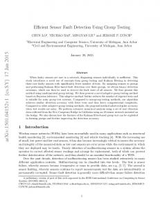
4.3 Simulation Results It is assumed that the fault is caused by a single parameter change, and the fault occurs at time 𝑡 = 10𝑠. The fault is sensor fault The fault is caused by the deviation of 𝑎3 . The value of 𝑎3 changes from 0 to 0.1, while the parameter 𝑎1 maintains as its nominal value 1 and 𝑎2 maintains as its nominal value 1. Figure 1 shows the results of the 2nd parameter filter of 𝑎3 , This is the case where 𝑠 = 𝑗 and the interval contains the faulty parameter value. The figure shows that after 𝑡𝑓 = 10𝑠, the signals of two observer estimation errors are always different, so this interval cannot be excluded from ”containing faulty parameter value”, and the parameter 𝑎3 can not be excluded from fault. Figure 2 shows the results of the first parameter filter of 𝑎3 . This is the case where 𝑠 = 𝑗 and the interval does not contain the faulty parameter value. The figure shows that after 𝑡𝑓 = 10𝑠, the signals of two observer estimation errors are the same, it means that this interval does not contain the faulty parameter value. Figure 3 shows the results of the 2nd parameter filter of the parameter 𝑎2 (actuator parameter). This is the case where 𝑠 ∕= 𝑗. The figure shows that after 𝑡𝑓 = 10𝑠, the signals of two observer estimation errors are the same, it means that this interval does not contain the faulty parameter value. The figure also shows that, the case where the signals of two observer estimation errors are the same occurs very close to the time 𝑡𝑓 (in this example, it occurs at the time 𝑡𝑓 .), therefore we can very quickly deicide that the interval does not contain the faulty parameter value, it guarantees the speediness of the isolation. Similarly, the simulation shows that all the intervals of the parameter 𝑎2 can be very quickly excluded from containing the faulty parameter value (limited by the length of the paper, the simulation curves of other intervals are not presented in the paper.), the parameter 𝑎2 is very quickly excluded from fault. Figure 4 shows the results of the 3rd parameter filter of the parameter 𝑎1 (dynamic parameter). This is the case where 𝑠 ∕= 𝑗. The figure shows that after 𝑡𝑓 = 10𝑠, the signals of two observer estimation errors are the same, it means that this interval does not contain the faulty parameter value, the figure also shows
4
21st International Workshop on Principles of Diagnosis
Table 3: The values of parameter filters of 𝑎3 N 𝑎𝑏3 𝑎𝑎3
1 0.00 0.05
2 0.05 0.15
3 0.15 0.20
Figure 1:
Figure 4: that this result can be decided very quickly. Similarly, the simulation shows that all the intervals of 𝑎1 do not contain the faulty parameter value, the parameter 𝑎1 is very quickly excluded from fault. Because the parameter 𝑎1 and the parameter 𝑎2 are excluded from fault, while the parameter 𝑎3 cannot, so the fault is in 𝑎3 . Because the exclusions of 𝑎1 and 𝑎2 are very quick, therefore the isolation is very quick.
Figure 2:
Figure 3:
The fault is actuator fault The fault is caused by the deviation of 𝑎2 . The value of 𝑎2 changes from 1 to 0.1, while the parameter 𝑎1 maintains as its nominal value 1 and 𝑎3 maintains as its nominal value 0. Figure 5 shows the results of the first parameter filter of 𝑎2 . This is the case where 𝑠 = 𝑗 and the interval contains the faulty parameter value. The figure shows that after 𝑡𝑓 = 10𝑠, the signals of two observer estimation errors are always different, so this interval cannot be excluded from ”containing faulty parameter value”, and the parameter 𝑎2 can not be excluded from fault. Figure 6 shows the results of the 2nd parameter filter of the parameter 𝑎3 (sensor parameter). This is the case where 𝑠 ∕= 𝑗. The figure shows that after 𝑡𝑓 = 10𝑠, the signals of two observer estimation errors are the same, it means that this interval does not contain the faulty parameter value, the figure also shows that this result can be decided very quickly. Similarly, the simulation shows that all the intervals of 𝑎3 do not contain the faulty parameter value, the parameter 𝑎3 is very quickly excluded from fault. Figure 7 shows the results of the 4th parameter filter of the parameter 𝑎1 (dynamic parameter). This is the case where 𝑠 ∕= 𝑗. The figure shows that after 𝑡𝑓 = 10𝑠, two curves of the two observer estimations almost superimpose together, the signals of two observer esti-
5
21st International Workshop on Principles of Diagnosis
Figure 8:
Figure 5:
mation errors are the same, it means that this interval does not contain the faulty parameter value. Similarly, the simulation shows that all the intervals of 𝑎1 do not contain the faulty parameter value, the parameter 𝑎1 is very quickly excluded from fault. As 𝑎1 and 𝑎3 are very quickly excluded from the fault, so the fault is very quickly located at the parameter 𝑎2 .
Figure 6:
The fault is dynamic fault The fault is caused by the deviation of 𝑎1 . The value of 𝑎1 changes from 1 to 0.73, while the parameters 𝑎2 and 𝑎3 maintains as their nominal value 1 and 0. For the case in the parameter filters of 𝑎1 , the simulation shows that 𝑎1 cannot be excluded from fault, this case has been discussed in the articles of our previous work (8; 10). Figure 8 shows the results of the 4th parameter filter of the parameter 𝑎2 (actuator parameter). This is the case where 𝑠 ∕= 𝑗. The figure shows that after 𝑡𝑓 = 10𝑠, the signals of two observer estimation errors are the same, it means that this interval does not contain the faulty parameter value. Similarly, the simulation shows that all the intervals of 𝑎2 do not contain the faulty parameter value, the parameter 𝑎2 is very quickly excluded from fault. For the parameter filters of 𝑎3 (sensor parameter), the simulation also shows that all the intervals of 𝑎3 do not contain the faulty parameter value, the parameter 𝑎3 is very quickly excluded from fault. As 𝑎2 and 𝑎3 are very quickly excluded from the fault, so the fault is very quickly located at the parameter 𝑎1 . 5
Figure 7:
CONCLUSION
In this paper, the parameter interval based fault isolation method is extended to sensor fault and actuator fault isolation problems for nonlinear dynamic systems. The parameter interval based fault isolation method can be used directly for sensor fault and actuator fault without need of any modifications. The example shows good performance of this method for sensor and actuator fault isolations.
6
21st International Workshop on Principles of Diagnosis
ACKNOWLEDGMENTS This work was supported by National Natural Science Foundation of P.R.China (60864003). REFERENCES (1) Hammouri, H., Kinnaert, M., and EI Yaagoubi, E. H. (1999). Observer based approach to fault detection and isolation for nonlinear systems. IEEE Transactions on Automatic Control, 44, 10, pp 1879-1884. (2) De Persis, C., and Isidori, A. (2001). A geometric approach to nonlinear fault detection and isolation. IEEE Transactions on Automatic Control, 46(6), pp 853-865. (3) Hammouri, H., Kabore, P., Othman, S., and Biston, J. (2002). Failure diagnosis and nonlinear observer application to a hydraulic process. Journal of the Franklin Institute, 339, pp 455-478. (4) Comtet-Varga, G., Cassar, J. Ph., and Staroswiecki, M. (1997). Analytic redundancy relations for state affine systems. Proceedings of the fourth European Control Conference (ECC’97, Brussels, Belgium). (5) Staroswiecki, M., and Comtet-Varga, G. (2001). Analytical redundancy relations for fault detection and isolation in algebraic dynamic systems. Automatica, 37, pp 687-699. (6) Zhang, Q. (2000). A new residual generation and evaluation method for detection and isolation of faults in non-linear systems. International Journal of Adaptive Control and Signal Processing, 14 (2000) 759-773. (7) Xu, A., and Zhang, Q. (2004). Nonlinear system fault diagnosis based on adaptive estimation. Automatica, 40, pp 1181-1193. (8) Zetao Li and B.Dahhou (2006). Parameter Intervals used for Fault Isolation in Nonlinear Dynamic Systems. International Journal of Modelling, Identification and Control, Vol. 1, No. 3, 2006. (9) Zetao Li and B.Dahhou (2007). Fault Isolation for Nonlinear Dynamic Systems Based on Parameter Intervals. International Journal of Systems Science, Vol.38,Issue7,2007,pp.531-547. (10) Zetao Li and B.Dahhou (2008). A New Fault Isolation and Identification Method for Nonlinear Dynamic Systems: Application to a Fermentation Process. Applied Mathematical Modelling, 32 (2008) 2806-2830. (11) Zhang, X. Parisini, T. Polycarpou, M.M. (2005). Sensor Bias Fault Isolation in a Class of Nonlinear Systems. IEEE Transactions on Automatic Control, March 2005 Volume: 50, Issue: 3, On page(s): 370- 376.
7