190
IEEE JOURNAL OF SOLID-STATE CIRCUITS, VOL. 49, NO. 1, JANUARY 2014
Sensor-to-Digital Interface Built Entirely With Carbon Nanotube FETs Max M. Shulaker, Jelle Van Rethy, Gage Hills, Hai Wei, Member, IEEE, Hong-Yu Chen, Georges Gielen, Fellow, IEEE, H.-S. Philip Wong, Fellow, IEEE, and Subhasish Mitra, Fellow, IEEE
Abstract—Low-power applications, such as sensing, are becoming increasingly important and demanding in terms of minimizing energy consumption, driving the search for new and innovative interface architectures and technologies. Carbon nanotube FETs (CNFETs) are excellent candidates for further energy reduction, as CNFET-based digital circuits are projected to achieve an order of magnitude improvement in energy-delay product compared with silicon-CMOS at highly scaled technology nodes. However, carbon nanotubes (CNTs) are inherently subject to imperfections and variations such as those induced by mispositioned and metallic CNTs. These substantial imperfections and variations have prevented the demonstration of complex CNFET circuits until now. This paper presents the first demonstration of a subsystem, which is a complete capacitive sensor interface circuit, implemented entirely using CNFETs that can be fabricated reproducibly in a VLSI-compatible fashion. This is made possible by: 1) a digitally oriented interface architecture and 2) the imperfection-immune design paradigm, which combines design and processing techniques to successfully overcome CNT imperfections and variations. In addition to electrical measurements, we demonstrate correct operation of our CNFET circuitry by interfacing it with a sensor used to control a handshaking robot. Index Terms—Carbon nanotube (CNT), carbon nanotube FET (CNFET), sensor interface circuit.
I. INTRODUCTION
L
OW-POWER applications, such as (wireless) sensing, are becoming increasingly important and demanding in terms of minimizing energy consumption while increasing performance. This drive for increased energy efficiency, which is often expressed in terms of performance per watt [1], [2], is motivating the search for alternative energy-efficient technologies. Carbon nanotube field-effect transistors (CNFETs) are highly promising candidates to complement silicon-CMOS in the future, due to their excellent electrostatic control and
Manuscript received April 24, 2013; revised July 08, 2013; accepted August 12, 2013. Date of publication October 01, 2013; date of current version December 20, 2013. This paper was supported by Guest Editor Tadahiro Kuroda. This work was supported in part by the National Science Foundation (CISE) under Grants CNS-1059020, CCF-0726791, CCF-0702343, and CCF-0643319, FCRP C2S2, FCRP FENA, STARNet SONIC, and the Stanford Graduate Fellowship. The work of M. Shulaker was supported by the Hertz Foundation Fellowship. The work of J. Van Rethy was supported by FWO Flanders. M. M. Shulaker, G. Hills, H. Wei, H.-Y. Chen, H.-S. P. Wong, and S. Mitra are with the Stanford University, Stanford, CA 94305 USA (e-mail:
[email protected];
[email protected];
[email protected];
[email protected];
[email protected];
[email protected]). J. Van Rethy and G. Gielen are with the KU Leuven, B-3001 Leuven, Belgium (e-mail:
[email protected]; Georges.Gielen@esat. kuleuven.be). Color versions of one or more of the figures in this paper are available online at http://ieeexplore.ieee.org. Digital Object Identifier 10.1109/JSSC.2013.2282092
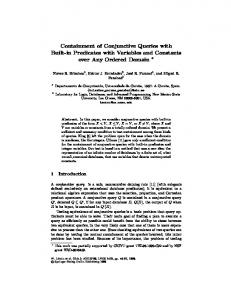
Fig. 1. Single CNFET. The scanning electron microscopy (SEM) image shows the source, drain, and channel region of a CNFET.
transport properties [3]. Experimental results have shown that, at highly scaled nodes (9-nm channel length), CNFETs can outperform FINFETs and Si-nanowires, providing the best current density at a low operating voltage of 0.5 V [4]. Additional work has shown complementary CNFET logic operating at a further reduced supply voltage of 0.4 V [5]. Due to these device-level improvements, CNFET circuits are projected to outperform current Si-CMOS circuits by over an order of magnitude improvement in energy-delay-product at highly scaled technology nodes [4], [6]. A typical CNFET is shown in Fig. 1. Multiple carbon nanotubes (CNTs) comprise the channel of the transistor, whose conductance is modulated by the gate. The gate, source, and drain are defined by traditional lithography, and the source–drain separation is limited by the minimum lithographic pitch. The inter-CNT pitch, however, is controlled by the CNT growth, and can therefore be much smaller than the minimum lithographic pitch. For increased current drive, the target inter-CNT spacing is 4–5 nm, corresponding to a CNT density of 200–250 CNTs m [4], [6], [7]. There have been important milestones for CNFET technologies since the initial discovery of CNTs and the first demonstrations of CNFETs [8]–[10]. Ballistic transport, sub-10-nm channel length, high CNT density, gate-all-around, and improved contact resistance have been demonstrated experimentally [4], [11]–[14]. These demonstrations, however, have all focused on isolated single CNFETs. Additionally, stand-alone and basic cascaded combinational logic elements, such as a ring oscillator fabricated along a single CNT, a single D-latch, a percolation transport-based decoder, and a pass-transistor logic-based full adder, have also been demonstrated [15]–[18]. However, the demonstration of more complex CNFET circuits have not been possible in the past due to
0018-9200 © 2013 IEEE
SHULAKER et al.: SENSOR-TO-DIGITAL INTERFACE BUILT ENTIRELY WITH CARBON NANOTUBE FETs
(a)
(b)
191
(c)
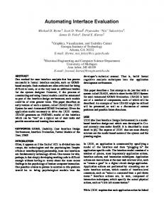
Fig. 2. Illustrations of inherent CNT imperfections and variations. (a) SEM of mispositioned CNTs. (b) – and s-CNT. (c) SEM showing CNT count variations.
characteristics for CNFETs composed of an m-CNT
Fig. 3. Chemical vapor deposition (CVD) growth of CNTs on a quartz substrate yield highly aligned CNTs.
inherent CNT imperfections and variations[19] (Fig. 2), given here. 1) Mispositioned CNTs can lead to stray conducting paths. These unwanted and incorrect connections in a circuit can cause incorrect logic functionality. 2) Metallic CNTs (m-CNTs), which have little or no bandgap due to their chirality, lead to severely degraded (decreased) , increased leakage current, and incorrect logic functionality. 3) CNT count variations (variations in the number of CNTs per CNFET), due to nonuniform inter-CNT spacing from the CNT growth and due to the presence and removal of m-CNTs, lead to possible functional failure of devices (CNFETs with no CNTs) and increased delay variations. In this paper, we successfully overcome the above obstacles, enabling an increased level of integration beyond single CNFETs or stand-alone logic elements for this emerging technology. We experimentally demonstrate, for the first time, a complete sub-system built entirely using CNFETs. This subsystem is a capacitive sensor to digital interface circuit [20]. To overcome inherent CNT imperfections, we use the imperfection-immune design paradigm [19], and, to control and minimize variations, we use CNT-specific aligned-active layout designs [19], [21]. While several publications have focused on using CNTs as sensors, for instance, using functionalized CNTs to sense specific molecules [22]–[24], our capacitive sensor interface circuit uses CNFET-based digital logic to interface with any capacitive sensor (CNT-based or other). This paper is organized as follows. Section II describes and provides experimental results realizing the methodology used to overcome the above-mentioned inherent CNT imperfections and variations. Section III describes in detail the architecture
and implementation of the capacitive sensor interface circuit demonstrated. Section IV presents the experimental results and characterization of the CNFET circuits, ranging from inverters to the entire capacitive sensor interface circuit. Section V concludes this paper. II. OVERCOMING CNT IMPERFECTIONS AND VARIATIONS To overcome inherent CNT imperfections, we employ the imperfection-immune design paradigm, which relies on a unique combination of CNT processing solutions and CNFET circuit design. We show that this methodology can be realized in practice, and can be used practically to build functional CNFET circuits, such as our CNFET sensor interface circuit. A. Overcoming Mispositioned CNTs It is currently not possible to guarantee exact alignment and positioning of all CNTs on a wafer, especially for large-scale CNFET circuits. The resulting mispositioned CNTs introduce stray conducting paths (Fig. 4), resulting in incorrect logic functionality. To overcome mispositioned CNTs, we perform a full wafer-scale aligned CNT growth [25]. This is accomplished by growing the CNTs on a quartz crystalline substrate, such that the CNTs grow preferentially along the crystalline plane of the substrate. After growth, the CNTs are transferred to a traditional amorphous substrate through a low-temperature (125 C) transfer method, which maintains the alignment and density of the CNTs [25]. The CNT transfer also has the advantage of decoupling the high-temperature CNT growth from the final wafer on which the CNFET circuits are fabricated, making the process Si-CMOS compatible. CNT alignment achieved by this growth and transfer process is 99.5%, rendering the majority of CNTs
192
IEEE JOURNAL OF SOLID-STATE CIRCUITS, VOL. 49, NO. 1, JANUARY 2014
(a)
(b)
Fig. 4. (a) Example of mispositioned CNTs causing incorrect logic functionality in a NAND gate. (b) Example of a mispositioned CNT-immune NAND gate design. Detailed process steps in reference [19].
very highly aligned (shown in Fig. 3) [25]. However, for VLSI circuits, 99.5% CNT alignment may not be sufficient. To overcome the presence of the remaining mispositioned CNTs, we employ the mispositioned CNT-immune design technique [19], [26]. This ensures that the resulting circuit is immune to any mis-positioned CNTs, and it can be applied to any arbitrary logic function. An example of a CNFET standard cell for a mispositioned CNT-immune NAND gate is shown in Fig. 4. The mispositioned CNT-immune design technique relies on etched regions defined within the standard cell, which etch away a section of an extended gate and any CNTs underneath this region. The positioning of the etched regions ensures that, if any mispositioned CNT could have caused incorrect logic functionality, part of that CNT would be etched out in this region, thus removing the CNT from the circuit. As the technique is implemented entirely within the standard cell, it does not require die-specific customization and is thus compatible with VLSI processing flows and VLSI design methodologies. Also, the technique has significantly smaller impact (in terms of area, power, and speed) compared with traditional redundancy-based defect- and fault-tolerance techniques [26]. B. Overcoming Metallic CNTs Typical CNT growths result in 5%–50% m-CNTs depending on the growth conditions [27], [28]. It is currently impossible to grow 100% semiconducting CNTs (s-CNTs). Thus, the m-CNTs must be removed after growth. For CNFET circuits to meet digital logic requirements, 99.99% of all m-CNTs must be removed [28]. Several methods exist for the removal of m-CNTs after growth, such as solution-based sorting [29], [30] and single-device electrical breakdown (SDB) [31]. Electrical breakdown, whereby a sufficiently large source–drain voltage is pulsed to breakdown m-CNTs through self-Joule heating (while a back-gate turns off all s-CNTs), has shown the ability to remove the required 99.99% m-CNTs for VLSI applications. While SDB can achieve such a high degree of m-CNT removal, it poses several scalability challenges [28]. To perform electrical breakdown in a VLSI-compatible manner, we use a combined CNFET processing and design technique called VLSI-compatible metallic carbon nanotube removal (VMR) [28]. VMR, performed as an additional fabrication
Fig. 5. Schematic illustrations of design and processing steps for VMR. Detailed process steps in reference [28].
step during circuit fabrication, relies on a design technique that allows electrical breakdown to be performed at the chip scale; this allows for any arbitrary CNFET circuit, such as our sensor-interface circuit, to undergo electrical breakdown all at once rather than on an individual CNFET basis. Fig. 5 illustrates how VMR is implemented. The VMR structure (inter-digitated electrodes at the minimum lithographic pitch) is patterned, and then electrical breakdown is performed on the entire VMR structure. After breakdown, the final circuit is fabricated (which involves removing unneeded sections of the VMR structure and etching away mispositioned CNTs following the mispositioned CNT-immune design technique). The remaining sections of the VMR structure act as the source–drain contacts of the CNFETs in the final circuit layout. Any arbitrary logic function can be implemented with VMR [28], while incurring minimal impact at the system level with an area overhead of less than 1% [32]. Two key figures of merit of any m-CNT removal technique, including VMR, are the percentage of grown m-CNTs that are removed, and the selectivity between preferentially removing m-CNTs versus inadvertently removing s-CNTs. To experimentally determine these figures of merit, electrical breakdown is performed on arrays of CNFETs, each composed of a single CNT. Each CNFET is measured to determine if it is metallic or semiconducting (threshold set as ), and then the breakdown voltage (pulsed for 1 s) needed to remove the CNT is recorded (Fig. 6). We fit a Gaussian distribution curve to the experimental data (with adjusted R-squared [33] values of 0.9995 and 0.9056 for m-CNTs and s-CNTs, respectively), and
SHULAKER et al.: SENSOR-TO-DIGITAL INTERFACE BUILT ENTIRELY WITH CARBON NANOTUBE FETs
193
Fig. 6. Breakdown voltage distribution of metallic CNTs (m-CNTs) and semiconducting CNTs (s-CNTs).
Fig. 9. Top left: schematic of 3 3 CNFET array. Bottom left: SEM of fabricated test structures, a 6 6 array of CNFETs (CNTs aligned in vertical direction). Right: SEM of a single column of CNFETs.
Fig. 7. Asymmetric correlations between CNFETs based on layout.
Fig. 8. Top: SEMs of CNFETs with channel widths of 2, 4, and 10 m, to include on average two, four, and ten CNTs, respectively. (Bottom): CNFET yield 300 CNFETs . increases with increased sizing of the CNFETs sample size
calculate that with an applied breakdown voltage of approximately 10.5 V, we can remove 99.99% of all m-CNTs within a VMR structure. Additionally, a high selectivity between m-CNTs and s-CNTs is achieved with 4% s-CNT removal. Furthermore, Section IV-A shows how VMR can be used to tune the electrical parameters of circuits in a VLSI-compatible manner after the fabrication of the CNFETs is completed. We thus demonstrate that VMR can overcome the presence of m-CNTs in our circuit. C. Overcoming CNT Count Variations One of the contributing factors to CNT count variations is the nonuniform distribution of inter-CNT spacing among grown CNTs across a wafer, resulting in local CNT density variations [19]. Therefore, as illustrated in Fig. 2, CNFETs of a specific width will not always be comprised of a fixed number
Fig. 10. Yield results for four different 6 size was 15 arrays, totaling 540 CNFETs.
6 CNFET arrays. Entire sample
Fig. 11. Block diagram of the capacitive sensor to digital interface circuit.
of CNTs, but rather have a variation in the number of CNTs per CNFET due to local CNT density variations. Additionally, due to the probabilistic presence of m-CNTs during CNT
194
IEEE JOURNAL OF SOLID-STATE CIRCUITS, VOL. 49, NO. 1, JANUARY 2014
Fig. 12. Circuit implementation of the capacitive sensor to digital interface circuit.
growth, the number of s-CNTs per CNFET will also vary. The probabilistic removal of both m-CNTs and s-CNTs during VMR (or any m-CNT removal technique) is therefore another source of variation for the final number of CNTs per CNFET (CNT count variation [19], [34]). Due to CNT count variations, there is a nonzero probability that a CNFET will be left with no CNTs, resulting in a functional failure of the CNFET. A naive solution to overcoming functional failures is upsizing CNFETs. Increasing the width of a CNFET increases the average number of CNTs per CNFET, thus exponentially reducing the probability of CNFET functional failure. Yet upsizing all CNFETs leads to significant energy penalties [21]. While naive upsizing improves circuit yield, it overlooks the opportunity to improve yield through taking advantage of properties unique to CNTs. Specifically, as shown in Fig. 7, due to the fact that CNTs are one-dimensional nanostructures, CNTs exhibit asymmetric correlations. For instance, if the active region (area of channel which has CNTs) of the CNFETs are aligned perpendicular to the direction of CNT growth, the CNFETs are comprised of different and distinct CNTs. These CNFETs are thus uncorrelated. However, if the active regions of CNFETs are aligned along the direction of CNT growth, then all CNFETs are comprised of essentially the same set of CNTs, and thus are highly correlated. This asymmetric CNT correlation provides a unique opportunity to improve yield otherwise limited by CNT count variations with only minimal upsizing. This results in less energy penalty than naively upsizing all CNFETs in a circuit. Special layouts, called aligned-active layouts, constrain the active regions of the CNFETs within the standard cell to be aligned along the direction of CNT growth [19]. By aligning the active regions of the CNFETs, the probability of having the entire column of CNFETs function or fail theoretically stays approximately at the probability of just a single CNFET functioning or failing, irrespective of the actual number of CNFETs in the column (for vertically oriented CNTs, as in Fig. 3). It has been calculated that aligned-active layouts and selective upsizing can improve (i.e., reduce) the probability of functional failures by over an order of magnitude at significantly reduced energy penalties associated with naive CNFET up-sizing [21], [35]. The costs of implementing aligned-active layouts at the
Fig. 13. Schematic and SEM of fabricated local back-gate CNFET.
standard cell-level and at the system-level are minimal [19], [21]. Additionally, the locations of I/O pins are retained as much as possible, minimizing the impact on inter-cell routing during place-and-route. For a detailed description of the aligned-active layout design technique for large-scale designs (aligned-active regions inside each standard cell, aligned-active regions between different cells on the same set of CNTs, and selective up-sizing to ensure high yield given that all standard cells cannot share the same set of CNTs in a large design), please refer to previous work [35]. We experimentally demonstrate, for the first time, techniques for improving CNFET circuit yield by engineering CNFET correlations through aligned-active layouts. Fig. 8 shows scanning electron microscopy (SEM) images of CNFETs of three different widths, with each CNFET on average including two, four, or ten CNTs. After performing m-CNT removal, the yields on sets of 100 CNFETs of each width are 69%, 90%, and 98%, respectively (Fig. 8). As expected, naively upsizing CNFETs (to include more CNTs per CNFET) decreases the probability of functional failure caused by CNFETs with no CNTs. For our capacitive sensor interface circuit, we thus set the minimum size CNFET to 10 CNTs, therefore achieving 100% yield of individual CNFETs in our larger circuits. To experimentally demonstrate the circuit yield enhancement of aligned-active layouts, we fabricate arrays of CNFETs, shown schematically in Fig. 9. The test arrays are composed of six rows and six columns of CNFETs, with the CNTs aligned along the vertical direction. CNFETs in a row of the array are
SHULAKER et al.: SENSOR-TO-DIGITAL INTERFACE BUILT ENTIRELY WITH CARBON NANOTUBE FETs
195
Fig. 14. Left: SEM showing a CNFET inverter array, with expanded SEM of an individual inverter. Right: cumulative distribution of the output voltage swing for the 381 functional inverters (out of 400).
comprised of distinct and different CNFETs and therefore are all uncorrelated and independent CNFETs. However, all CNFETs in a column of the array have their active regions aligned along the direction of the CNTs (vertically) and thus contain essentially the same set of CNTs (though not necessarily exactly identical CNTs due to nonidealities such as mispositioned CNTs and CNTs of nonequal lengths). Therefore, all CNFETs in a column are highly correlated (even though not necessarily exactly identical). A very small active region width is chosen, so that all CNFETs are comprised of 2 CNTs. Therefore, as previously stated, the CNFETs have an expected individual yield of 69% . Supposing a circuit comprised of only six CNFETs , the theoretical circuit yield for uncorrelated and independent CNFETs is greatly reduced to 10.8% . Experimentally, the average yield of a row comprising of 6 uncorrelated CNFETs is 8.9% (95% confidence intervals from 3% to 15%), close to the theoretically expected 10.8%. However, the average yield of a column comprising of six highly correlated CNFETs, and therefore following the aligned-active layout constraint, is greatly increased to 59% (95% confidence intervals from 49% to 69%), close to the theoretically expected 69% (assuming perfect correlation). The layout and SEMs of a test array are shown in Fig. 9. Fig. 10 shows yields of the CNFETs from four such arrays. We thus experimentally demonstrate that aligned-active layouts can significantly improve the yield of CNFET circuits. This, along with minimal upsizing, allows for the realization of larger circuits, such as our capacitive sensor interface circuit. III. SENSOR INTERFACE CIRCUIT DESIGN Now that the imperfection-immune design methodology can successfully be realized experimentally, we demonstrate a complete subsystem built entirely out of CNFETs: a capacitive sensor interface circuit that converts a capacitive sensor signal to a digital output. A. Architecture To implement such sensor interfaces, innovative circuit architectures are currently being explored. With technology scaling, the accompanying reduction in supply voltage limits the voltage headroom for traditional analog amplitude-based architectures
Fig. 15. Tunable circuit properties (inverter output voltage swing and gain) by varying the applied breakdown voltage used during VMR (sample size is 381 inverters from Fig. 14).
[36], which in turn increases the power consumption needed to retain the same signal-to-noise ratio (SNR) [37]. Shifting the processing of the sensor information from the amplitude domain to the time/frequency domain allows the use of fully digital circuity rather than analog circuity, overcoming the limitation of the decreasing voltage headroom [38]. Circuits operating at 0.3–0.4 V become possible and show a low power consumption. Our implemented capacitive sensor interface circuit architecture is inspired by Danneels et al. [38] and is based on a first-order bang-bang phase-locked loop structure (BBPLL) [39], [40]. The advantages of BBPLL include smaller chip area, low power consumption, scalability to smaller technologies, robustness to process variations, and low-voltage capabilities [39]. The capacitive sensor interface circuit we have implemented has two key attributes: 1) fully digital architecture 2) direct conversion from the capacitive sensor information to the frequency domain, avoiding any intermediate transformation of the capacitive sensor to the voltage domain. The block diagram of our circuit is shown in Fig. 11. The circuit consists of two main blocks: a frequency-modulating block, which converts the sensor information to the frequency domain, and a frequency-demodulating block, which converts the frequency to the digital domain, resulting in a complete sensor-to-digital flow. The frequency-modulating block consists of a sensor-controlled oscillator (SCO) and directly converts the capacitive value of the sensor to a corresponding
196
IEEE JOURNAL OF SOLID-STATE CIRCUITS, VOL. 49, NO. 1, JANUARY 2014
Fig. 16. Characterization of fabricated ring oscillators shows the expected trends of decreasing oscillation frequency with decreasing supply voltage and with increasing number of stages in the ring oscillator.
frequency in the frequency domain. The frequency-demodulating block is a digital first-order BBPLL, consisting of a single-bit phase detector, a zeroth-order digital filter and a digitally controlled oscillator (DCO), which converts the sensor frequency to a digital equivalent. The single-bit phase detector functions as a single-bit quantizer, and its output is the single-bit digital output of the system. The architecture resembles a -modulator, as it has inherent first-order quantization noise shaping. Also, the output is oversampled to increase the resolution of the single-bit output [40]. B. Implementation The full circuit implementation is shown in Fig. 12 and is implemented entirely using CNFET-based digital logic gates. Both the SCO and DCO are implemented as two matched nine-stage inverter-based ring oscillators. The variable capacitance of the sensor acts as a variable load on a single stage of the SCO, thereby generating a sensor-controlled frequency . The variable capacitive load on the DCO takes one of two values, as a fixed capacitance value is swapped in or out of one stage of the DCO depending on the feedback from the single-bit phase detector, creating a digitally controlled frequency . The value of is chosen by design to be the maximum possible value of the capacitive sensor on the SCO, thus ensuring that is always either faster or slower than . The single-bit phase detector, implemented as a D-latch, compares the phases of and , and thus compares whether the SCO leads or lags the DCO. If the PLL is locked onto , then the average values over time of and are equal, and thus the two frequency controls of the SCO and DCO are correlated. Since both oscillators are implemented identically, the control of the SCO, the sensor value, is correlated to the control of the DCO, the single-bit output of the phase detector. Hence the value of the sensor is digitized in this single-bit DCO control signal. IV. EXPERIMENTAL CNFET CIRCUIT PERFORMANCE The CNFET circuit has been fabricated following the process described by Shulaker et al. [41]. We use local back-gate CNFETs, as shown in Fig. 13. The entire fabrication process is performed wafer-scale on a single wafer, and is VLSI-compatible as there is no customization of any sort. All of the CNFETs and interconnects are predetermined during design, and there is no post-fabrication selection, configuration or fine-tuning of functional CNFETs. All CNFETs have channel length 1 ,
Fig. 17. Frequency modulation: monotonic relationship between the oscillation frequency and the sensor value for three SCOs, demonstrating repeatability of the process.
3 V, and 5 V, and therefore there is no tuning of individual CNFETs, maintaining VLSI-compatibility. While CNFETs offer the potential for great energy savings, our circuit is limited to the 3-V supply voltage due to fabrication limitations of an academic facility channel length 1 m . We implement PMOS-only logic, and thus the sizing of the pull-up networks is either 10 or 20 the widths of the pulldown networks for increased gain and swing. As explained in Section II-C, we use aligned-active layouts for each subcomponent (inverters and D-latch) for significant yield benefits. All CNFETs have approximately between 10 and 200 CNTs, depending on their relative sizing. While we implement PMOSonly logic, CMOS is not a fundamental challenge for CNFETs, as there are several experimental demonstrations of complementary CNFET circuits [18], [42], [43]. A. Process Robustness and Control We used arrays of inverters to characterize the control and robustness of the fabrication process and design. Arrays of CNFET inverters were fabricated, as shown in Fig. 14, using mispositioned CNT immune design, VMR, and aligned-active layout. Out of 400 inverters, 381 were functional (failures were clustered and not due to CNTs, but due to fabrication limitations, e.g., bad lithography). While implementing PMOS-only logic, we still obtain the vast majority of the output voltage swing (Fig. 14). In addition to demonstrating a vast majority of functional inverters, we show the ability to control the inverter properties through the use of VMR and the m-CNT removal process. A key advantage of VMR is that the m-CNT removal process is based on an electrical measurement of the circuits, and thus the electrical properties of the CNFETs are used to
SHULAKER et al.: SENSOR-TO-DIGITAL INTERFACE BUILT ENTIRELY WITH CARBON NANOTUBE FETs
197
Fig. 18. Output waveform of the D-latch, tested at 1 kHz; all possible transitions are tested.
guide VMR. For instance, Lin et al. demonstrated that, for single CNFETs, the threshold voltages and ratios are affected by the choice of applied breakdown voltage [44]. As shown in Fig. 6, while a breakdown voltage of approximately 10.5 V is ideal for selectivity between m-CNTs and s-CNTs, a slight modification of the actual applied breakdown voltage while performing VMR can be used to finely tune the circuit parameters during fabrication. We show that by varying the applied breakdown voltage during VMR, the inverter characteristics such as gain and output voltage swing can be controlled (Fig. 15). Based on the results from Fig. 15, there is a tradeoff between removing as few s-CNTs as possible and using a slightly higher breakdown voltage to achieve better inverter properties. It should be noted that, since electrical breakdown selectively removes CNTs based on their electrical properties, the additional s-CNTs removed are selectively removed due to shifted threshold voltages, leaking off-state current, or other electrical properties. After characterization of the applied breakdown voltage versus the output voltage swing and the gain of the inverters, the ideal breakdown voltage for the circuit is selected, and this new voltage is applied once to the entire circuit for all subsequent wafers, in a VLSI-compatible fashion. In the end, we select a breakdown voltage of 14 V. B. Ring Oscillators A level of complexity above stand-alone inverters are ring oscillators, which function as the core of the capacitive sensor interface circuit. Correct functionality of the ring oscillators, along with their ability to perform frequency modulation, is fundamental to the circuit operation. Characterization of the CNFET ring oscillators yields the expected trends in oscillation frequency versus the supply voltage and versus the number of stages in the ring oscillator (Fig. 16). To characterize the frequency modulation performed by the SCO, the oscillation frequency of the ring oscillator is measured for varying values of the capacitive load. As shown in Fig. 17, the oscillation frequency of an SCO decreases monotonically with increasing capacitive load value (with a nominal frequency in the range of 0.9–1.1 kHz). We
Fig. 19. SEM images of the CNFET-based sensor interface circuit. Top: two full circuits. Bottom: magnified view of two vertically stacked CNFETs following aligned-active layout.
thus show successful frequency modulation, the crux of the capacitive sensor interface circuit. Moreover, Fig. 17 shows successful frequency modulation of multiple different SCOs to demonstrate the robustness and repeatability of our process. Additionally, the correct functionality of the single-bit phase detector, a D-latch, is shown in Fig. 18. C. Capacitive Sensor Interface Circuit An SEM image of the final fabricated capacitive sensor interface circuits is shown in Fig. 19. All fabrication steps, from CNT growth to the final circuit fabrication, were performed at the Stanford Nanofabrication Facility. The sensor used during the measurements is an external capacitive sensor. The correct operation of the entire sensor interface circuit is experimentally verified by measuring the digital output for different sensor values. The output, as mentioned above, is taken as the digitized single-bit output of the phase detector (which is also the control signal of the DCO). To increase resolution, we oversample this output by taking its average duty cycle over time. An example of the experimentally measured and digitized output of the circuit over time is shown in Fig. 20 for a range
198
IEEE JOURNAL OF SOLID-STATE CIRCUITS, VOL. 49, NO. 1, JANUARY 2014
Fig. 20. Experimentally measured (dotted lines) and digitized (solid lines) over-sampled outputs of the full CNFET sensor interface circuit (over time), for different values of the capacitive sensor.
Fig. 21. Correct functionality of the complete CNFET interface circuit, with 5.5% rms error between the measured and the simulated outputs.
of capacitive sensor values. The average duty cycle calculated over 20 ms is plotted in Fig. 21 and increases monotonically for increasing sensor values. This shows that the implemented circuit functions correctly. The mismatch between the measured and the expected outputs (obtained through simulations using the Stanford CNFET SPICE Model [45]) is 5.5% (calculated as the root-mean-square error). The nonlinearity that can be seen in Fig. 21 (the input–output curve) is attributed to the circuit topology. Any nonlinearity in the tuning curve (frequency versus capacitive load) of the SCO is directly translated into the same nonlinearity in the input–output curve for a first-order system [40]. Since the frequency of the SCO inherently has a -relation with the value of the sensor capacitance, this relationship can also be seen in the overall input–output curve of the sensor interface. The entire capacitive sensor circuit consumes 336 W from a 3-V supply. Since the nominal frequency of the circuit (SCO and DCO frequency) is in the kHz range and has to be oversampled to increase the resolution, the bandwidth is in the range of tens of Hz. To demonstrate the correct functionality of the circuit, the CNFET interface circuit has been attached to a handshaking robot to act as a human interface. The handshaking robot operates as follows: when a person holds the robotic hand, a sensor is swapped into the circuit at the SCO, changing the value of the
Fig. 22. Image of the live demonstration of the CNFET-controlled handshaking robot at ISSCC 2013.
capacitive sensor (to be sensed). The CNFET circuit responds with a change in the output duty cycle, which triggers an actuator attached to the robot. The robot thus shakes hand with a person. Fig. 22 shows an image of the live demonstration of the handshaking robot, as was demonstrated by Shulaker et al., at the IEEE International Solid-State Circuits Conference (ISSCC) on February 17, 2013 [20]. A video of the CNFET handshaking robot can be found at [46]. V. CONCLUSION CNFETs offer the potential for significant improvements in energy efficiency. However, while high-performance isolated CNFETs and stand-alone logic elements have been demonstrated, inherent CNT imperfections and variations have prohibited larger and more complex CNFET circuits. We show experimentally that the imperfection-immune design paradigm can overcome the inherent CNT imperfections, and experimentally demonstrate the ability to control and minimize variations through CNT-specific aligned-active layout designs. As a result, these experimental realizations enable integration and successful demonstration of larger and complex CNFET
SHULAKER et al.: SENSOR-TO-DIGITAL INTERFACE BUILT ENTIRELY WITH CARBON NANOTUBE FETs
circuits, such as the presented complete capacitive sensor interface circuit. We experimentally demonstrate the following factors. 1) Effectiveness of VMR is shown, by removing 99.99% of all m-CNTs while inadvertently removing only 4% s-CNTs. VMR can also tune circuit parameters such as gain and output voltage swing after device fabrication, in a VLSI-compatible manner. 2) Yield enhancement of CNFET circuits is demonstrated through both CNFET upsizing and CNFET correlation engineering using aligned-active layouts. 3) Robust and repeatable CNFET circuits are shown, allowing for multiple and repeatable working circuits. 4) The first complete subsystem built entirely using CNFETs is demonstrated: a capacitive sensor signal-to-digital interface circuit, which has been interfaced with a handshaking robot as a human interface for demonstration. Thus, from the experimental characterization of smaller CNFET circuits to the demonstration of the first-ever complete subsystem of a sensor interface built entirely out of CNFETs, we have shown that CNT-based technologies are indeed a viable emerging technology with promising potential for low-energy and high-performance circuit implementations. Future work to realize the energy efficiency promise of CNFET circuits must be demonstrated at scaled technology nodes (sub-10 nm), and must tackle device non-idealities, such as low CNT density and high contact resistance. While challenges towards realizing high-performance and highly energy-efficient CNFET circuits still remain, there have been several promising solutions that can potentially overcome these challenges [4], [15], [41], [47]. REFERENCES [1] J. Laudon, “Performance/watt: The new server focus,” ACM SIGARCH Computer Architecture News, vol. 33, no. 4, pp. 5–13, 2005. [2] S. Rivoire, M. A. Shah, P. Ranganathan, and C. Kozyrakis, “JouleSort: A balanced energy-efficiency benchmark,” in Proc. ACM SIGMOD Int. Conf. Management of Data, Jun. 2007, pp. 365–367. [3] J. Appenzeller, “Carbon nanotubes for high-performance electronics—Progress and prospect,” Proc. IEEE, vol. 96, no. 2, pp. 201–211, Feb. 2008. [4] A. D. Franklin, M. Luisier, S. J. Han, G. Tulevski, C. M. Breslin, L. Gignac, M. S. Lundstrom, and W. Haensch, “Sub-10 nm carbon nanotube transistor,” Nano Lett., vol. 12, no. 2, pp. 758–762, 2012. [5] L. Ding, S. Liang, T. Pei, Z. Zhang, S. Wang, W. Zhou, J. Liu, and L. M. Peng, “Carbon nanotube based ultra-low voltage integrated circuits: Scaling down to 0.4 V,” Appl. Phys. Lett., vol. 100, no. 26, 2012, Art. ID 263116. [6] L. Wei, D. Frank, L. Chang, and H.-S. P. Wong, “A non-iterative compact model for carbon nanotube FETs incorporating source exhaustion effects,” in Proc. IEEE Int. Electron Devices Meeting, 2009, pp. 917–920. [7] N. Patil, J. Deng, S. Mitra, and H.-S. P. Wong, “Circuit-level performance benchmarking and scalability analysis of carbon nanotube transistor circuits,” IEEE Trans. Nanotechnol., vol. 8, no. 1, pp. 37–45, Jan. 2009. [8] I. Sumio, “Helical microtubules of graphitic carbon,” Nature, vol. 354, no. 6348, pp. 56–58, 1991. [9] R. A. Martel, T. Schmidt, H. R. Shea, T. Hertel, and P. Avouris, “Single- and multi-wall carbon nanotube field-effect transistors,” Appl. Phys. Lett., vol. 73, no. 17, p. 2447, 1998. [10] S. J. Tans, A. R. Verschueren, and C. Dekker, “Room-temperature transistor based on a single carbon nanotube,” Nature, vol. 393, no. 6680, pp. 49–52, 1998. [11] A. Javey, J. Guo, Q. Wang, M. Lundstrom, and H. Dai, “Ballistic carbon nanotube transistors,” Nature, vol. 424, pp. 654–657, 2003.
199
[12] Q. Cao, S. J. Han, G. S. Tulevski, Y. Zhu, D. D. Lu, and W. Haensch, “Arrays of single-walled carbon nanotubes with full surface coverage for high-performance electronics,” Nature Nanotechnol., vol. 8, no. 3, pp. 180–186, 2013. [13] A. D. Franklin, S. O. Koswatta, D. Farmer, G. S. Tulevski, J. T. Smith, H. Miyazoe, and W. Haensch, “Scalable and fully self-aligned n-type carbon nanotube transistors with gate-all-around,” in Proc. Int. Electron. Devices Meet., Dec. 2012, pp. 4–5. [14] Y. Chai, A. Hazeghi, K. Takei, H. Y. Chen, P. C. Chan, A. Javey, and H. S. Wong, “Low-resistance electrical contact to carbon nanotubes with graphitic interfacial layer,” IEEE Trans. Electron Devices, vol. 59, no. 1, pp. 12–19, Jan. 2012. [15] C. Zhihong, J. Appenzeller, Y. Lin, J. Sippel-Oakley, A. G. Rinzler, J. Tang, S. J. Wind, P. M. Solomon, and P. Avouris, “An integrated logic circuit assembled on a single carbon nanotube,” Science, vol. 311, no. 5768, pp. 1735–1735, 2006. [16] N. Patil, A. Lin, J. Zhang, H. Wei, K. Anderson, H.-S. P. Wong, and S. Mitra, “Scalable carbon nanotube computational and storage circuits immune to metallic and mis-positioned carbon nanotubes,” IEEE Trans. Nanotechnol., vol. 10, no. 4, pp. 744–750, Jul. 2011. [17] Q. Cao, H. S. Kim, N. Pimparkar, J. P. Kulkarni, C. Wang, M. Shim, and J. A. Rogers, “Medium-scale carbon nanotube thin-film integrated circuits on flexible plastic substrates,” Nature, vol. 454, no. 7203, pp. 495–500, 2008. [18] L. Ding, Z. Zhang, S. Liang, T. Pei, S. Wang, Y. Li, W. Zhou, J. Liu, and L. M. Peng, “CMOS-based carbon nanotube pass-transistor logic integrated circuits,” Nature Commun., vol. 3, p. 677, 2012. [19] J. Zhang, L. Wei, N. Patil, A. Lin, H. Wei, H.-S. P. Wong, and S. Mitra, “Robust digital VLSI using carbon nanotubes,” IEEE Trans. Computer-Aided Design (CAD) Integr. Circuits Syst., vol. 31, no. 4, pp. 453–471, Apr. 2012. [20] M. Shulaker, J. Van Rethy, G. Hills, H. Y. Chen, G. Gielen, H. S. Wong, and S. Mitra, “Experimental demonstration of a fully digital capacitive sensor interface build entirely using carbon nanotube FETs,” in Proc. Int. Solid State Circuits Conf., 2013, pp. 112–113. [21] J. Zhang, N. Patil, H. S. Wong, and S. Mitra, “Overcoming carbon nanotube variations through co-optimized technology and circuit design,” in Proc. Int. Electron. Devices Meet., Dec. 2011, pp. 4–6. [22] F. Qu, M. Yang, J. Jiang, G. Shen, and R. Yu, “Amperometric biosensor for choline based on layer-by-layer assembled functionalized carbon nanotube and polyaniline multilayer film,” Analytical Biochem., vol. 334, no. 1, pp. 108–114, 2005. [23] X. Tang, S. Bansaruntip, N. Nakayama, E. Yenilmez, Y. L. Chang, and Q. Wang, “Carbon nanotube DSA sensor and sensing mechanism,” Nano Lett., vol. 6, no. 8, pp. 1632–1636, 2006. [24] T. Zhang, M. B. Nix, B. Y. Yoo, M. A. Deshusses, and N. V. Myung, “Electrochemically functionalized single-walled carbon nanotube gas sensor,” Electroanalysis, vol. 18, no. 12, pp. 1153–1158, 2006. [25] N. Patil, A. Lin, E. R. Myers, H.-S. P. Wong, and S. Mitra, “Integrated wafer-scale growth and transfer of directional carbon nanotubes and misaligned-carbon-nanotube-immune logic structures,” in Proc. Symp. VLSI Technol., Jun. 2008, pp. 205–206. [26] N. Patil, J. Deng, A. Lin, H. S. Wong, and S. Mitra, “Design methods for misaligned and mis-positioned carbon-nanotube-immune circuits,” IEEE Trans. Comput. Aided Design (CAD) Integr. Circuits Syst., vol. 27, no. 10, pp. 1725–1736, Oct. 2008. [27] L. Ding, A. Tselev, J. Wang, D. Yuan, H. Chu, T. P. McNicholas, and J. Liu, “Selective growth of well-aligned semiconducting single-walled carbon nanotubes,” Nano Lett., vol. 9, no. 2, pp. 800–805, 2009. [28] N. Patil, A. Lin, J. Zhang, H. Wei, K. Anderson, H.-S. P. Wong, and S. Mitra, “VMR: VLSI-compatible metallic carbon nanotube removal for imperfection-immune cascaded multi-stage digital logic circuits using carbon nanotube FETs,” in Proc. Int. Electron. Devices Meet., Dec. 2009, pp. 573–576. [29] M. S. Arnold, A. A. Green, J. F. Hulvat, S. I. Stupp, and M. C. Hersam, “Sorting carbon nanotubes by electronic structure using density differentiation,” Nature Nanotechnol., vol. 1, no. 1, pp. 60–65, 2006. [30] M. C. LeMieux, M. Roberts, S. Barman, Y. W. Jin, J. M. Kim, and Z. Bao, “Self-sorted, aligned nanotube networks for thin-film transistors,” Science, vol. 321, no. 5885, pp. 101–104, 2008. [31] P. G. Collins, M. S. Arnold, and P. Avouris, “Engineering carbon nanotubes and nanotube circuits using electrical breakdown,” Science, vol. 292, no. 5517, pp. 706–709, 2001. [32] H. Wei, N. Patil, J. Zhang, A. Lin, H. Y. Chen, H.-S. P. Wong, and S. Mitra, “Efficient metallic carbon nanotube removal readily scalable to wafer-level VLSI CNFET circuits,” in Proc. Symp. VLSI Technol., Jun. 2010, pp. 237–238.
200
IEEE JOURNAL OF SOLID-STATE CIRCUITS, VOL. 49, NO. 1, JANUARY 2014
[33] G. R. Terrell, “Mathematical statistics: A unified introduction,” in . Berlin, Germany: Springer, 1999. [34] S. Borkar, A. Keshavarzi, J. K. Kurtin, and K. Vivek, “Statistical Circuit Design With Carbon Nanotubes,” U.S. Patent Applicat. 2 007 0155 065, 2005. [35] J. Zhang, S. Bobba, N. Patil, A. Lin, H.-S. P. Wong, G. D. Micheli, and S. Mitra, “Carbon nanotube correlation: Promising opportunity for CNFET circuit yield enhancement,” in Proc. Des. Automat. Conf., Jun. 2010, pp. 889–892. [36] S. Chatterjee, Y. Tsividis, and P. Kinget, “0.5 V analog circuit techniques and their application in OTA and filter design,” IEEE J. SolidState Circuits, vol. 40, no. 12, pp. 2373–2387, Dec. 2005. [37] A. J. Annema, B. Nauta, R. van Langevelde, and H. Tuinhout, “Analog circuits in ultra-deep-submicron CMOS,” IEEE J. Solid-State Circuits, vol. 40, no. 1, pp. 132–143, Jan. 2005. [38] H. Danneels, K. Coddens, and G. Gielen, “A fully-digital, 0.3 V, 270 nW capacitive sensor interface without external references,” in IEEE Proc. ESSCIRC, Sep. 2011, pp. 287–290. [39] N. Da Dalt, “A design-oriented study of the nonlinear dynamics of digital bang-bang PLLs,” IEEE Trans. Circuits Syst. I, Reg. Papers, vol. 52, no. 1, pp. 21–31, Jan. 2005. [40] J. Van Rethy, H. Danneels, and G. Gielen, “Performance analysis of energy-efficient BBPLL-based sensor-to-digital converters,” IEEE Trans. Circuits Syst. I, Reg. Papers, vol. 60, no. 8, pp. 2130–2138, Aug. 2013. [41] M. Shulaker, H. Wei, N. Patil, J. Provine, H. Y. Chen, H. S. Wong, and S. Mitra, “Linear increases in carbon nanotube density through multiple transfer technique,” Nano Lett., vol. 11, no. 5, pp. 1881–1886, May 2011. [42] H. Wei, H. Y. Chen, L. Liyanage, H. S. Wong, and S. Mitra, “Air-stable technique for fabricating n-type carbon nanotube FETs,” in Proc. Int. Electron. Devices Meet., Dec. 2011, pp. 22–23. [43] Z. Zhiyong, X. Liang, S. Wang, K. Yao, Y. Hu, Y. Zhu, Q. Chen, W. Zhou, Y. Li, Y. Yao, J. Zhang, and L. M. Peng, “Doping-free fabrication of carbon nanotube based ballistic CMOS devices and circuits,” Nano Lett., vol. 7, no. 12, pp. 2603–2607, 2007. [44] A. Lin, N. Patil, K. Ryu, A. Badmaev, L. G. De Arco, C. Zhou, and H. S. Wong, “Threshold voltage and on-off ratio tuning for multiple-tube carbon nanotube FETs,” IEEE Trans. Nanotechnol., vol. 8, no. 1, pp. 4–9, Jan. 2009. [45] J. Deng and H. S. Wong, “A compact SPICE model for carbon-nanotube field-effect transistors including nonidealities and its applications—Part II: Full device model and circuit performance benchmarking,” IEEE Trans. Electron Devices, vol. 54, no. 12, pp. 3195–3205, Dec. 2007. [46] M. Shulaker, “SACHA: The Stanford Carbon Nanotube Controlled Handshaking Robot,” Stanford Univ., Stanford, CA, USA, Mar. 19, 2013 [Online]. Available: http://www.youtube.com/watch?v=rj4jyZlwQEc [47] S. W. Hong, T. Banks, and T. J. A. Rogers, “Improved density in aligned arrays of single-walled carbon nanotubes by sequential chemical vapor deposition on quartz,” Adv. Mater., vol. 22, no. 16, pp. 1826–1830, 2010.
Max M. Shulaker received the B.S. degree in electrical engineering from Stanford University, Stanford, CA, USA, in 2011, where he is currently working toward the Ph.D. degree. His current work deals with experimentally demonstrating nano-systems with emerging technologies. His current research focus is on realizing increased levels of integration for carbon-nanotube based digital logic circuits. Mr. Shulaker is a Stanford Graduate Fellow and a Fannie and John Hertz Fellow.
Jelle Van Rethy was born in Geel, Belgium, in 1986. He received the M.Sc. degree in electrical engineering from KU Leuven, Leuven, Belgium, in 2010, where he is currently working toward the Ph.D. degree in electrical engineering. His current research interests include energy-efficient, noise-resilient mixed-signal ICs for sensor interfacing.
Gage Hills received the B.S. degree in electrical engineering and computer science from Yale University, New Haven, CT, USA, in 2007, and the M.S. degree in electrical engineering from Stanford University, Stanford, CA, USA, in 2011, where he is currently working toward the Ph.D. degree. After completing his undergraduate work, he worked on the development of 3-D time-of-flight cameras, first with Canesta Inc., a startup in Sunnyvale, CA, USA, and then at Microsoft. His research interests involve the demonstration and modeling of emerging nanotechnologies, especially those based on carbon nanotubes.
Hai Wei (S’09) received the B.S. degree (with honors) in microelectronics from Tsinghua University, Beijing, China, in 2007, and the M.S. degree in electrical engineering from Stanford University, Stanford, CA, USA, in 2010, where he is currently working toward the Ph.D. degree. His current research interests include design and fabrication of carbon nanotube field-effect transistors and circuits and monolithic 3-D integrated circuits. Mr. Wei was a recipient of the Stanford School of Engineering Larry C-K. Yung Fellowship Award.
Hong-Yu Chen received the B.S. degree in electrical engineering from National Tsing Hua University, Hsinchu, Taiwan, in 2007, and the M.S. degree in electrical engineering from Stanford University, Stanford, CA, USA, in 2011, where he is currently working toward the Ph.D. degree under the supervision of Prof. H.-S. Philip Wong. His research interests at Stanford include processing technology and the characterization of emerging resistive switching memory, carbon nanotubes material synthesis, device characterization, and circuit integration. To date, he has authored/coauthored over 40 technical papers. He held summer internship positions with Applied Materials Inc., IMEC, and SanDisk Inc., in 2011, 2012, and 2013 respectively. Mr. Chen was the recipient of several awards, including the Intel Fellowship 2013–2014, Taiwanese Government scholarships to study abroad (GSSA) 2012–2014, the IEEE Electron Devices Society Ph.D. Student Fellowship 2013, and the Best Student Paper Award of the 2011 VLSI Technology Symposium.
Georges Gielen (F’02) received the M.Sc. and Ph.D. degrees in electrical engineering from the Katholieke Universiteit Leuven, Leuven, Belgium, in 1986 and 1990, respectively. In 1990–1991, he was a Visiting Lecturer and Postdoctoral Researcher with the Department of Electrical Engineering and Computer Science, University of California, Berkeley, CA, USA. He then returned to the ESAT-MICAS Laboratory of the Katholieke Universiteit Leuven where he was appointed an Assistant Professor in 1993. He became a Full Professor in 2000 and has served as Chair of the Department of Electrical
SHULAKER et al.: SENSOR-TO-DIGITAL INTERFACE BUILT ENTIRELY WITH CARBON NANOTUBE FETs
Engineering (ESAT) since August 2012. He is also the Chair of the Leuven ICT (LICT) research center and the PI coordinator of the Leuven CHIPS Center of Excellence. His research interests are in the design of analog and mixed-signal integrated circuits, and especially in analog and mixed-signal CAD tools and design automation (modeling, simulation and symbolic analysis, analog synthesis, analog layout generation, analog and mixed-signal testing). He is coordinator or partner of several (industrial) research projects in this area, including several European projects. He has authored or coauthored seven books and more than 450 papers in edited books, international journals, and conference proceedings. Prof. Gielen regularly is a member of the Program Committees of international conferences (including DAC, ICCAD, ISCAS, DATE, and CICC) and served as General Chair of the DATE conference in 2006 and of the ICCAD conference in 2007. He serves regularly as member of editorial boards of international journals (the IEEE TRANSACTIONS ON CIRCUITS AND SYSTEMS, the IEEE TRANSACTIONS ON COMPUTER-AIDED DESIGN, International Journal on Analog Integrated Circuits and Signal Processing, and Integration). He was the recipient of the 1995 Best Paper Award in the John Wiley international journal on Circuit Theory and Applications, and was the 1997 Laureate of the Belgian Royal Academy on Sciences, Literature and Arts in the discipline of Engineering. He received the 2000 Alcatel Award from the Belgian National Fund of Scientific Research for his innovative research in telecommunications, and won the DATE 2004 conference Best Paper Award. He served as an elected member of the Board of Governors of the IEEE Circuits And Systems (CAS) Society, as appointed member of the Board of Governors of the IEEE Council on Electronic Design Automation (CEDA), and as Chairman of the IEEE Benelux CAS Chapter. He served as the President of the IEEE CAS Society in 2005, and as Chair of the IEEE Benelux Section in 2009–2011. He is the Chair of EDAA. He was elected DATE Fellow in 2007, and received the IEEE Computer Society Outstanding Contribution Award and the IEEE Circuits and Systems Society Meritorious Service Award in 2007.
H.-S. Philip Wong (F’01) received the B.Sc. (Hons.) degree from the University of Hong Kong, the M.S. degree from Stony Brook University, Stony Brook, NY, USA, and the Ph.D. degree from Lehigh University, Bethlehem, PA, USA. He is the Willard R. and Inez Kerr Bell Professor with the School of Engineering, Stanford University, Stanford, CA, USA. He joined Stanford University as a Professor of electrical engineering in September 2004. From 1988 to 2004, he was with the IBM T. J. Watson Research Center. Yorktown Heights, NY, USA. At IBM, he held various positions from Research Staff Member to Manager, and Senior Manager. While he was a Senior Manager, he had the responsibility of shaping and executing IBM’s strategy on nanoscale science and technology as well as exploratory silicon devices and semiconductor technology. His present research covers a broad range of topics including carbon electronics, biosensors, self-assembly, exploratory logic devices, nanoelectromechanical relays, device modeling, and nonvolatile memory devices such as phase change memory and metal–oxide resistance change memory. Prof. Wong served on the Electron Devices Society AdCom as elected member (2001–2006). He served as the editor-in-chief of the IEEE
201
TRANSACTIONS ON NANOTECHNOLOGY in 2005–2006, subcommittee Chair of the ISSCC (2003–2004), General Chair of the IEDM (2007), and is currently a member of the Executive Committee of the Symposia of VLSI Technology and Circuits (2007–2010). His academic appointments include the Chair of Excellence of the French Nanosciences Foundation, Guest Professor of Peking University, Honorary Professor of the Institute of Microelectronics of the Chinese Academy of Sciences, and the Honorary Doctorate degree from the Institut Polytechnique de Grenoble, France.
Subhasish Mitra (F’13) received the Ph.D. degree in electrical engineering from Stanford University, Stanford, CA, USA. He directs the Robust Systems Group in the Department of Electrical Engineering and the Department of Computer Science, Stanford University, Stanford, CA, USA, where he is the Chambers Faculty Scholar of Engineering. Prior to joining Stanford, he was a Principal Engineer with Intel Corporation. His research interests include robust system design, VLSI design, CAD, validation and test, and emerging nanotechnologies. His X-Compact technique for test compression has been key to cost-effective manufacturing and high-quality testing of a vast majority of electronic systems, including numerous Intel products. X-Compact and its derivatives have been implemented in widely-used commercial Electronic Design Automation tools. The QED and IFRA techniques, created jointly with his students, have shown outstanding results in overcoming critical bottlenecks in post-silicon validation and debug for several commercial hardware platforms, and have been characterized as “breakthrough” in a Research Highlight in the Communications of the ACM. His work on the first demonstration of carbon nanotube imperfection-immune digital VLSI, jointly with his students and collaborators, was selected by the National Science Foundation (NSF) as a Research Highlight to the United States Congress, and was highlighted as “a significant breakthrough” by, among others, the Semiconductor Research Corporation (SRC), the MIT Technology Review, and the New York Times. Prof. Mitra was the recipient of the Presidential Early Career Award for Scientists and Engineers from the White House, the highest United States honor for early-career outstanding scientists and engineers, Terman Fellowship, IEEE CAS/CEDA Pederson Award for the best paper published in the IEEE TRANSACTIONS ON COMPUTER-AIDED DESIGN OF INTEGRATED CIRCUITS AND SYSTEMS, Intel Divisional Recognition Award “for a breakthrough soft error protection technology,” and the Intel Achievement Award, Intel’s highest corporate honor, “for the development and deployment of a breakthrough test compression technology.” He and his students presented award-winning papers at several major conferences: IEEE/ACM Design Automation Conference, IEEE International Test Conference, IEEE VLSI Test Symposium, Intel Design and Test Technology Conference, and the Symposium on VLSI Technology. At Stanford, he was honored several times by graduating seniors “for being important to them during their time at Stanford.” He has served on numerous conference committees and journal editorial boards. Recently, he served on the Defense Advanced Research Projects Agency’s (DARPA) Information Science and Technology (ISAT) Board as an invited member.