Sensorless Variable Speed Single-Phase Induction Motor Drive System M. Caruso*,V. Cecconi*,A.O. Di Tommaso*, R. Rochat * Department of Electrical, Electronic, Telecommunications and Automation Engineering University of Palermo Vialle delle Scienze, Ed. 9, 90128, Palermo, Italia E-mail:
[email protected]@
[email protected] tDepartment of Control and Automation Engineering, School of Mines, Federal University of Ouro Preto Campus Morro do Cruzeiro, 35400-000, Ouro Preto, Minas Gerais, Brazil E-mail:
[email protected]
Abstract-It is usual find single-phase induction motor (SPIM) in several house, office, shopping, farm, and industry appli cations, which are become each time more sophisticated and requiring variable speed drives. Considering the low cost of
switched series capacitor in the auxiliary winding, which can be controlled to improve the machine performance at different operating conditions [1]-[4].
this machine, the adoption of sensorless speed control is the more reasonable option for SPIM drives. This paper presents a proposal for sensorless variable speed SPIM drive based on direct rotor field orientation techuiques. An observer based on two independent linear close-loop control systems provides the estimation of the rotor flux and speed from the measurements of the stator currents and voltages. These estimatives are used by close-loop systems for speed control and flux regulation in order to determine the voltages to be applied in the main and auxiliary windings by a three-legs VSI inverter. None variable transforma tion is used in this proposal in order to eliminate the asymmetry of the stator windings of the SPIM. The performance of the proposed sensorless speed control is satisfactorily demonstrated from computer simulations considering two situations: variations on rotor speed reference and the application of mechanical load.
Index Terms-Sensorless, Variable Speed Drives, Single-Phase Induction Motor, Direct Field Orientation.
I.
INTRODUCTION
Traditionally used in fractional and sub-fractional horse power applications, the single-phase induction motor (SPIM) is usually found in several house, office, shopping, farm, and industry appliances such as air conditioning systems, mixers, washers, blowers, dryers, fans, refrigerators, vacuum cleaners, compressors, pumps, etc. A SPIM is basically an unbalanced electric machine constituted by a squirrel-cage rotor and two asymmetrical stator windings displaced 900 in space and with different impedances. When the machine is fed by a single phase power source, the main winding produces a pulsating and stationary magnetic field, while the auxiliary winding, usually connected with a series capacitor, emulates a second phase to obtain the start-up torque for the SPIM. Although the auxiliary winding is often disconnected by a centrifugal switch when the SPIM rotor reaches 60% to 80% of rated speed, it can be maintained at running operation in order to provide a higher and less pulsating torque. Many proposals to improve the SPIM performance are based in the use of an electronically
978-1-4673-0342-2/12/$31.00 ©2012 IEEE
The development of more sophisticated applications and the introduction of low-cost static power converters have stimulated the development of variable speed drives for SPIM. The most of the control techniques for the SPIM drive are based on the use of constant V IF relation or on vectorial control with field orientation, usually utilizing appropriate variable transformations in order to eliminate the asymmetry of the stator windings [5]-[12]. Sensorless techniques is the more reasonable option for the control of fractional and low cost SPIM applications, since the small size and low cost of this motor does not justify the use of speed sensors due to reduction of reliability and increase of complexity, cost, difficulties, weight, size, and electrical susceptibility. Some approaches have been suggested for sensorless control of SPIM drives, where the rotor speed estimation are usually obtained from the machine model and the measurements of stator voltages and currents [4], [10], [12]-[14]. This paper presents a proposal for sensorless variable speed SPIM drive based on direct rotor field orientation techniques. An observer based on two independent linear close-loop control systems provides the estimations of the rotor flux from the measurements of the stator currents and voltages, allowing a better rotor flux regulation which is decoupled of the torque control. From these rotor flux observers, the rotor speed is evaluated. These estimatives are used by close-loop systems for speed control and flux regulation in order to determine the voltages to be applied in the main and auxiliary windings by a three-legs VSI inverter. None variable transformation is used in this proposal in order to eliminate the asymmetry of the stator windings of the SPIM. The performance of the proposed sensorless speed control is satisfactorily demonstrated from computer simulations considering two situations: variations on rotor speed reference and the application of mechanical load.
731
ICIT
2012
II.
DYNAMIC MODEL OF THE
SPIM
Traditionally, the dynamic model of a SPIM is described considering a stationary reference frame aj3 fixed in the stator, where a and j3 respectively denote the auxiliary and main windings [15]. Considering all rotor variables referred to the stator windings, the dynamic voltage equations of SPIMs are given by:
>-sa >-s{3 >-ra . Ar{3
=
=
=
=
Vsa - Rsaisa
(1)
vs{3 - Rs{3is{3
(2)
Vra - Rraira - NWr Ar{3 Wr Ara . vr{3 - Rr{3zr{3 + �
(3) (4)
where v voltage, W speed, R resistance, and N transformer ratio between both stator windings. The subscripts s and r are related respectively to stator and rotor variables and parameters. Since the SPIM has a squirrel-cage rotor, the rotor windings of SPIM are short-circuited and rotor voltages Vra and Vra are null. The flux equations are: =
=
Asa As{3 Ara Ar{3
=
=
=
=
=
=
Lsaisa + Lma (isa + ira) Ls{3is{3 + Lm{3 (is{3 + ir(3)
(5)
Lraira
+ Lma (isa +
ira)
(7)
Lr{3ir{3
+ Lm{3 (is{3 +
ir(3)
(8)
where L winding inductance and Lm mutual inductance. The instantaneous electromagnetic torque Te can be expressed by: =
=
Te
=
N
�
(Lm{3is{3ira - Lmaisair(3)
III. FLUX
Lma -L O'Ct
=
·
Ara
=
-
Lra Vsa L ma
+
Rra Ra , -L Ara - L L Zsa ra ret rna
+
ua N
)
Ua Rra , ( Ara - Lmazsa) Lra N
" Zs{3
=
, Ar{3
Lm{3 -L (1{3
Lr{3 -L Vs{3 m{3
+
(11)
Rr{3 R(1{3 , -L Ar{3 - L L Zs{3 - NU{3 r{3 r{3 m{3
)
(12) =
Rr{3 , (Ar{3 - Lm{3zs(3) -Lr{3
where Ua =
(
+
NU{3
(13)
Wr Ar{3, u{3 Wr Ara, R(1 RsL; + RrL�, and LsLr - L�, Admitting the nonlinear terms Ua and u{3 =
=
a-
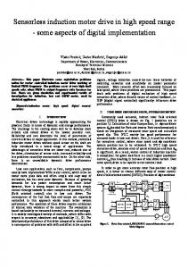
and ,B-Aux observers
=
as the system inputs, the SPIM model is a linear system, Thus, a rotor flux observer can be designed as the two independent linear close-loop control systems presented in Fig. 1 in order to
_
-
S2L(1{3
-s NLm{3 + s R{3 + Rs{3 Rr{3
(14)
where R{3 Rr{3Ls{3 + Rs{3Lr{3. This transfer function presents a zero in the origin, which provides a derivative action that does not contribute to reduce the current error, increasing the observer sensitive to noises and disturbances. In order to eliminate the effects of the derivative action of j3-model, a PI structure is considered for j3-compensator: =
U{3(s) is{3(s) - IS{3(s)
(10)
j3-model
•
L(1
(
is{3(s) U(3(s)
OBSERV ER
a-model
" Zsa
Block diagram of
obtain the observed '\r when is converges to measured stator current is. Analyzing only the structure of j3-flux observer, the open loop transfer function between is{3 and u{3 admitting vs{3 as system disturbance is given by
(9)
If the stator currents is and the rotor flux Ar vectors are admitted as the state variables, this dynamic model can be written as: •
Fig, 1.
(6)
=
k
/ +S z{3
(15)
The zero z{3 of the j3-compensator can be chosen to cancel the slowest pole of the open-loop transfer function of the Eq. 14, increasing the stability range and improving the speed response of the j3-flux observer. The gain k{3 determines the j3-compensator performance and can be designed in order to increase the observer robustness, minimizing the influence of the parameter variations over the flux estimation. Since PI compensator introduces a pure integrator in the close-loop transfer function of the j3-observer, a first-order high-pass filter with a very low cutoff frequency is inserted in the path of the estimated flux in order to prevent problems related to DC offset of the voltage and current sensors. Al though this solution can deteriorate the dynamic performance of the proposed flux observer at very low rotor speed, it can be considered satisfactory for the speed range that a SPIM usually
732
v
�
v �
��
xp
i,.
i,.
9 a�·to-dq conversion
A,.
OO�r " 00, "
0 a�·to-dq conversion
i.1I
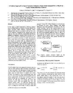
Fig. 2.
dq-to-(l� conversion
x,
Voj! �f1uxobserver
ioj!
i,
x,
x. Voj!
A.�r
00,
a-flux observer
e
Ud
'"
Rotational speed estimation using flux observers
e Fig. 3.
works. In order to reduce the effect of measurement noises in the observer performance, a first-order low-pass filter with an adequate cutoff frequency could be inserted in the measured current input to filter high frequencies signals. All principles used to analyze and design the ,8-observer can be similarly applied to the a-observer. IV.
COORDINATES SY STEM CONV ERSION AND ROTOR SPEED ESTIMATION
If the observation of the rotor fluxes is satisfactory, an esti mative of the rotor speed wr can be obtained from the proposed observer structure. Applying the a,8-to-dq transformation
Xd Xq
Xa cos() + x{3 sin ()
(16)
-Xa sin() + x{3 cos()
(17)
=
=
as presented in the Fig. 2, where the trigonometric functions are given by
Block diagram for flux and speed control
is controlled using the orthogonal current component is q established by a PI regulator
Isq
=
(
8 + Zw , kpw --8 - nre! - nr
'xm
=
J-X';'a
+ 'x;{3
(19)
the observer outputs originally described in a stationary reference frame a,8 fixed in the stator are converted into rotating dq-coordinates aligned to flux vector. The orthogonal components 'xr and Ud are null while the direct components q 'xrd and uq correspond to estimated rotor flux vector 'xr and nonlinear term Wr'xr. The rotor speed wr can be estimated as:
W, r V.
=
uq
-A
>"rd
(20)
ROTOR FLUX REGULATION AND ROTOR SPEED CONTROL
Since the variables are described in rotating dq-coordinates system aligned to the flux vector, vectorial techniques can be used in the control of the SPIM drive. A PI regulator can determine the direct current component isd in order to regulate the rotor flux
Isd
=
kp)..
8
� Z).. (Are! - Ar )
(21)
where the zero z).. could eliminate the slowest pole of the flux open-loop transfer function. The electromagnetic torque
(22)
whose the zero Zw is chosen to cancel the slowest pole of the mechanical open-loop transfer function. Using the eqs. 10 and 12, the stator voltages Vsd and Vs q can be obtained from the stator currents isd and is as:
Vsd
=
Vsq
q L Rra ma' Ar kpvsa ( 8 + zvsa) Isd Lra 2
=
kpvs{3 (
8
+
Zvs{3) Isq
+
Lm{3 , NU Lr{3 q
(23) (24)
where: (25)
(18)
cos()
)
(26) From the insertion of the eqs. 21 and 22 in the eqs. 23 and 24, the original PI regulators are converted into PID controllers in whose outputs are added feed-forward terms to determine the stator voltage components, as shown in the Fig. 3. Eventually, if the zero zvs{3 is significantly greatest than the zero zw, the derivative action introduced by the voltage equation can be neglected since its influence over the control system tends to quickly extinguished, and a simple PI regulator could be used in the speed close-loop control structure. The rotating dq voltage components are converted into stationary reference frame a,8 fixed in the stator in order to obtain the voltages Vsa and Vs{3 to be applied in the SPIM drive. VI. VSI
DRIVE
The VSI topology is the best choice for a small power drive for fractional horsepower electric machines. In this work, it is considered that the SPIM windings are fed by two quadrature AC voltages generated by an three-leg voltage source inverter, a configuration that presents many advantages over the two-leg topology such as the generation of a zero voltage vector, without circulation of AC current in the DC link capacitor, and a better quality of the output voltage in terms of harmonic distortion [12], [16]-[20]. The three-leg VSI topology considered in this paper is shown in the Fig. 4.
733
TABLE I SPIM DATA Rated values
110 V 5U/00 Hz 2700 RPM 2 0.25 HP (180 W)
Voltage t