Sensorless Direct Torque Control (DTC) of induction motor drive is a ...... [67] and Nash [82] provide a good treatment of ACS600 and DTC. DTC has also been ...
AL-AZHAR UNIVERSITY FACULTY OF ENGINEERING (Cairo) ELECTRICAL ENGINEERING DEPT.
Parameters Estimation for Sensorless Induction Motor Drives Using Intelligent Techniques THESIS Submitted in fulfillment of the requirement for the degree of
Master of Science in Electrical Power & Machines, Faculty of Engineering (Cairo), Al-Azhar University By Mohammed Hamouda Ali (B.Sc. Electrical Engineering) Faculty of Engineering (Cairo), Al-Azhar University Under supervision of: Prof.Dr. Abd Elsamie Basiouny Kotb
Dr. Salama Abo-Zaid Abo Al-Ela
Professor of Electrical Machines
Lecture of Electrical Power & Machines
Faculty of Engineering (Cairo) Al-Azhar University
Faculty of Engineering (Cairo) Al-Azhar University
Cairo 2016 I
Acknowledgement First and foremost, I would like to begin by thanking Allah, Most Strong, All Almighty, for providing me the strength and perseverance required to achieve this work. I would like to thank and express my appreciation to my supervisor, Prof. Dr. Abd Elsamia Basiouny Kotb, for his encouragement and patience during my research work. It has been my honor and privilege to work under his supervision. His enthusiasm, guidance and insight throughout the duration of this study were invaluable to me. I would like to extend my appreciation and deep thanks to, Dr. Salama Abo-Zaid Abo Al-Ela, I’m deeply indebted for my current achievements to the invaluable guidance I have been receiving from him. His advice, and critical discussions are the main factors that helped me to accomplish this work. It has been a great opportunity to work with my colleagues in the electrical machines research group. I would like to thank all of them, for their cooperation and fruitful discussions. I would like to express my sincere gratitude, thanks, and love to my PARENTS for their continuous encouragement and love during the period of study. I would like to extend my gratitude to my family to have their support and care all these years. I got mainly from them the strength and inspiration that enabled me to finish this work. Finally, I would like to express my gratitude to my wife and my Sons for their patience, care, and support through the most difficult periods of this work. To her goes a great part of my gratitude.
IV
ABSTRACT Sensorless Direct Torque Control (DTC) of induction motor drive is a simple control method has less computational requirements and fast electromagnetic torque response. It doesn't need current controller and coordinate transformations such as Field Oriented Control (FOC) strategy. DTC has a common disadvantage of high torque ripple resulting in an additional losses and noise. Sampling frequency of conventional DTC is not constant and also only one voltage space vector is applied for the entire sampling period. Hence the motor torque may exceed the upper/lower torque limit even if the error is small, because it will take the same action if the error is small or big. In order to overcome this problem space vector modulation (SVM) method was proposed. By using SVM technique with DTC, the sampling frequency is maintained constant and reduced torque ripple with low switching losses. Also, the application of Fuzzy logic and artificial neural network (Artificial Intelligent Techniques) result in reducing torque, flux and current ripples and good estimation for parameters which need for DTC. In this thesis, there is an introduction of DTC and its improvement through improvement of switching table. This work is mainly focused on the state observers to estimate the states that are used in the DTC algorithms. Furthermore, model reference adaptive system (MRAS) is used to estimate the rotor speed in parallel with the stator resistance. In this work, it is also shown that the rotor speed estimation performance of these schemes quite satisfactory in the simulations. Also, it is proposed to apply the artificial intelligent techniques as a switching state selector, replacing the conventional speed controller and sector detection. A simulation results using Matlab/Simulink is given for conventional and intelligent sensorless DTC and show the application of intelligent techniques lead to better results and reduced ripples for torque, flux and current.
V
TABLE OF CONTENTS
TABLE OF CONTENTS
PAGE
ACKNOWLEDGEMENT ................................................................................................. IV ABSTRACT ..................................................................................................................V TABLE OF CONTENTS ........................................................................................... VI LIST OF TABLES ...................................................................................................... IX LIST OF FIGURES .....................................................................................................X LIST OF SYMBOLES ............................................................................................. XIII LIST OF ABBREVIATION ..................................................................................... XV
CHAPTER 1 ................................................................................................................ 1 INTRODUCTION ...................................................................................................... 1 1.1 PREFACE .......................................................................................................... 1 1.2 HISTORICAL REVIEW ....................................................................................... 2 1.3 THESIS OVERVIEW........................................................................................... 7 CHAPTER 2 ................................................................................................................ 9 SPEED CONTROL OF INDUCTION MOTORS ................................................ 9 2.1 INTRODUCTION ................................................................................................ 9 2.2 THE SCALAR SPEED CONTROL METHODS ..................................................... 11 2.2.1 Scalar Control Method strategy ............................................................. 12 2.2.2 Scalar Control Classification ................................................................. 13 2.2.2.1 Open-loop scalar control ................................................................. 13 2.2.2.2 Closed-loop scalar control ............................................................... 14 2.2.3 Features of Scalar Control ..................................................................... 15 2.3 VECTOR CONTROL METHOD .......................................................................... 16 2.3.1 Algorithm of vector control ................................................................... 16 2.3.2 Strategy of Vector Control of Induction Motor Drive ........................... 19 2.3.2.1 Vector transforms ............................................................................ 19 2.4 FIELD ORIENTATION CONTROL (FOC) ........................................................... 21 2.4.1 Methods of Field Orientation Control (FOC) ........................................ 22 2.4.1.1 Direct Field Orientation Method (DFO) ......................................... 23 2.4.1.2 Indirect Field Orientation Method (IFO)......................................... 24 2.4.2 The property of the FOC methods ......................................................... 26 2.4.3 A few of the salient features of FOC ..................................................... 27 2.5 DIRECT TORQUE CONTROL (DTC) ................................................................ 27 2.5.1 History of DTC ...................................................................................... 30 2.5.2 Direct Torque Control Strategy ............................................................. 31 2.5.3 The Basic Principles of Direct Torque Control of Induction Motor ...... 32 2.5.4 Basic principles of Switching Table ...................................................... 32 2.5.5 Stator Flux Linkage and Torque Control ............................................... 34 VI
TABLE OF CONTENTS
2.5.6 Direct Torque Control Schematic .......................................................... 35 2.5.6.1 Speed Controller .............................................................................. 35 2.5.6.2 Torque controller ............................................................................. 35 2.5.6.3 Torque/Flux Comparators ............................................................... 36 2.5.6.4 Optimal Switching Logic ................................................................ 36 2.5.6.5 Torque Production ........................................................................... 37 2.5.7 Direct Torque Control with Three Phase Inverter ................................. 38 2.5.8 Vector Model OF Inverter Output Voltage ............................................ 38 2.5.9 Classical Direct Torque Control (DTC) ................................................. 39 2.5.9.1 Stator Flux Control .......................................................................... 39 2.5.9.2 Stator Flux and Torque Estimation ................................................. 40 2.5.10 Improvement of the Switching Table .................................................. 42 2.5.11 DTC Twelve Sector Table (DTC_12).................................................. 43 2.5.12 Features of Direct Torque Control ....................................................... 45 2.5.12 The Properties of DTC ......................................................................... 46 2.6 PARAMETER ESTIMATION FOR SENSORLESS DTC ......................................... 48 2.6.1 Model Reference Adaptive System (MRAS) ........................................ 52 2.6.1.1 Model Reference Adaptive System Scheme (MRASF) .................. 53 2.6.2 Parallel Stator Resistance and Rotor Speed Estimation ......................... 55 CHAPTER 3 .............................................................................................................. 61 ARTIFICIAL INTELLIGENT TECHNIQUES ................................................. 61 3.1 INTRODUCTION .............................................................................................. 61 3.2 ARTIFICIAL NEURAL NETWORKS .................................................................. 62 3.2.1 Neuron Model ........................................................................................ 65 3.2.1.1 Single-Input Neuron ........................................................................ 65 3.2.1.2 Neuron with Vector Input................................................................ 66 3.2.2 Network Architectures ........................................................................... 67 3.2.2.1 A Single Layer of Neurons .............................................................. 67 3.2.2.2 Multiple Layers of Neurons ............................................................ 68 3.2.3 Transfer Functions ................................................................................. 70 3.2.4 Benefits of neural networks ................................................................... 70 3.3 FUZZY LOGIC CONTROL (FLC) ..................................................................... 73 3.3.1 Application Areas of Fuzzy Logic Controllers ...................................... 73 3.3.2 Components of FLC ............................................................................... 73 3.3.2.1 Fuzzification Block or Fuzzifier...................................................... 74 3.3.2.2 Inference System ............................................................................. 75 3.3.2.3 Defuzzification Block or Defuzzifier .............................................. 75 3.3.3 Features of Fuzzy logic .......................................................................... 76 3.3.4 Advantages of Fuzzy Logic for System Control.................................... 77 3.4 FUZZY NEURAL NETWORKS .......................................................................... 77 3.5 GENETIC ALGORITHMS (GA) ........................................................................ 80 VII
TABLE OF CONTENTS
3.5.1 Biological Terminology ......................................................................... 81 3.5.2 Components and Structure of GA .......................................................... 82 CHAPTER 4 .............................................................................................................. 83 SIMULATION, RESULTS AND DISCUSSION ................................................ 83 4.1 INTRODUCTION .............................................................................................. 83 4.2 SIMULATION MODEL ..................................................................................... 84 4.2.1 Three phase inverter ............................................................................... 85 4.2.2 Measures ................................................................................................ 85 4.2.3 Induction motor ...................................................................................... 85 4.2.4 Speed controller ..................................................................................... 85 4.2.5 Direct Torque Controller........................................................................ 85 4.2.6 MRAS .................................................................................................... 88 4.3 MODEL PARAMETERS .................................................................................... 90 4.4 SIMULATION FOR THE ARTIFICIAL INTELLIGENT TECHNIQUES ....................... 91 4.4.1 DTC BASED NEURAL NETWORK ................................................................ 91 4.4.2 Neural switching table ........................................................................... 92 4.4.3 Neural speed controller .......................................................................... 94 4.5 DIRECT TORQUE FUZZY CONTROL (DTFC) .................................................. 94 4.5.1 Fuzzification of Input and output linguistic Variables .......................... 95 4.5.2 DTFC Rule Base Model Design ............................................................ 97 4.5.3 Fuzzy switching table ............................................................................ 97 4.6 SIMULATION RESULTS ................................................................................... 97 4.6.1 Torque and speed results ........................................................................ 98 4.6.1.1 Conventional DTC .......................................................................... 98 4.6.1.2 Neural network DTC ....................................................................... 99 4.6.1.3 Double ANN-DTC ........................................................................ 101 4.6.1.4 Fuzzy logic DTC ........................................................................... 103 4.6.2 Stator flux circle results ....................................................................... 105 4.6.3 Stator current results ............................................................................ 108 4.6.4 Stator resistance estimation.................................................................. 111 CHAPTER 5 ............................................................................................................ 114 CONCLUSION AND FUTURE WORK ............................................................ 114 5.1 CONCLUSION ............................................................................................... 114 5.2 FUTURE WORK ........................................................................................ 115 REFERENCES ....................................................................................................... 116 APPENDIX A .......................................................................................................... 133 APPENDIX B .......................................................................................................... 133 APPENDIX C .......................................................................................................... 134 APPENDIX D .......................................................................................................... 134 VIII
LIST OF TABLES
LIST OF TABLES
PAGE
Table 2.1 The switching table logic...….……………………….………….…….34 Table 2.2 switching table for Conventional DTC………………...….……….….41 Table 2.3 The switching table for Modified DTC ….…….....…...……….…......42 Table 2.4 show the behavior of each state just in the first zone for the Conventional DTC (C_DTC) and the modified DTC (M_DTC) ...……………..43 Table 2.5 Table for sectors 12 and 1 in the12_DTC...…………………..….........44 Table 2.6 Switching table for the 12_DTC.………………….………...…….......45 Table 2.7 Comparison between DTC & FOC……………….………….……......47 Table 4.1 parameters for IM……………...…………….…….………………......90 Table 4.2 comparison between ripple values for DTC methods.…………..…....104 Table 4.3 comparison between ripple values for stator flux estimation...…........108 Table 4.4 comparison between ripple values for stator current...…………….....111 Table 4.5 comparison between ripple values for stator resistance estimation......113
IX
LIST OF FIGURES
LIST OF FIGURES
PAGE
Fig 2.1 General classification of induction motor control method .......................... 11 Fig 2.2 Torque speed characteristic at constant flux ................................................ 13 Fig 2.3 Open-loop V/Hz constant control ................................................................. 14 Fig 2.4 Closed-loop V/Hz constant control............................................................... 15 Fig 2.5 Simple representation of separately excited DC motor ............................... 18 Fig 2.6 Separately excited DC motor ........................................................................ 19 Fig 2.7 Clarke transformation .................................................................................... 20 Fig 2.8 Principles of vector control ........................................................................... 21 Fig 2.9 Position of the rotor flux vector .................................................................... 21 Fig 2.10 Field oriented control implementation principle with machine 𝒅 − 𝒒 model…………………………………………………………………………...22 Fig 2.11 Block diagram of the Direct Field Oriented Control (DFOC) .................. 23 Fig 2.12 Direct Field Orientation control (phasor diagram) .................................... 24 Fig 2.13 Block diagram of the Indirect Field Oriented Control (IFOC) ................. 25 Fig 2.14 Indirect Field orientation control (phasor diagram) .................................. 26 Fig 2.15 Block diagram of the Direct Torque Control of Induction motor ............. 29 Fig 2.16 The hysteresis controllers a) two-level, b) three-level .............................. 33 Fig 2.17 (a): The hysteresis band controls the stator flux voltage, (b): The torque is controlled by the three level hysteresis bands. ......................................................... 33 Fig 2.18 Block diagram of the Direct Torque Control of Induction motor ............. 35 Fig 2.19 Available stator voltage vectors .................................................................. 36 Fig 2.20 Estimated air-gap torque with hysteresis control ....................................... 37 Fig.2.21 Three phase voltage inverter ....................................................................... 38 Fig 2.22 Conventional DTC and its six sectors ........................................................ 39 Fig 2.23 Modified DTC and its new six sectors ....................................................... 42 Fig.2.24 Twelve sector modified DTC (12_DTC) .................................................... 44 Fig 2.25 Sensorless DTC control structure ............................................................... 49 Fig 2.26 Basic configuration of the rotor flux-based MRAS speed estimator ....... 53 Fig 2.27 Structure of the modified MRAS system for parallel rotor speed and stator resistance estimation ................................................................................................... 55 Fig 3.1 Schematic Drawing of Biological Neurons .................................................. 63 X
LIST OF FIGURES
Fig 3.2 Single-Input Neuron ...................................................................................... 66 Fig 3.3 a single R-element input vector .................................................................... 66 Fig 3.4 A one-layer network with R input elements and S neurons ........................ 67 Fig 3.5 Multiple Layer Neural Network.................................................................... 68 Fig 3.6 Basic principle of operation for the Neural network ................................... 69 Fig 3.7 Hard-Limit Transfer Function ....................................................................... 70 Fig 3.8 Linear Transfer Function ............................................................................... 70 Fig 3.9 log-sigmoid Transfer Function ...................................................................... 70 Fig 3.10 Fuzzy Logic Controller Structure ............................................................... 74 Fig 3.11 The first model of fuzzy neural system ...................................................... 79 Fig 3.12 The second model of fuzzy neural system ................................................. 79 Fig 4.1 Simulink model of sensorless DTC .............................................................. 84 Fig 4.2 Simulink model of the speed controller........................................................ 85 Fig 4.3 Simulink model of the torque and flux calculator ....................................... 86 Fig 4.4 Three phase to 𝛂 − 𝛃 stationary reference frame (abc to 𝛼𝛽) .................... 86 Fig 4.5 Simulink model of the flux and torque hysteresis controller ...................... 86 Fig 4.6 Simulink model of the flux sector seeker ..................................................... 87 Fig 4.7 Simulink model of the switching table ......................................................... 87 Fig 4.8 Simulink model of MRASF speed estimator ............................................... 88 Fig 4.9 Simulink model of modified MRASF .......................................................... 88 Fig 4.10 Simulink model of Reference Model ......................................................... 89 Fig 4.11 Simulink model of Adaptive Model ........................................................... 89 Fig 4.12 Simulink model of adaptive mechanism for speed estimator ................... 90 Fig 4.13 Simulink model of adaptive mechanism for stator resistance estimator .. 90 Fig 4.14 Direct torque neural networks controller scheme ...................................... 91 Fig 4.15 Simulink model of the switching table using neural network ................... 92 Fig 4.16 Neural network training window ................................................................ 93 Fig 4.17 Training performance curve for the neural network .................................. 93 Fig 4.18 Simulink model of the PI controller using neural network ....................... 94 Fig 4.19 Proposed DTFC functional block diagram ................................................ 94 Fig 4.20 Flow chart for DTC using fuzzy logic ........................................................ 95 Fig 4.21 Block diagram of DTC using fuzzy logic controller ................................. 95 XI
LIST OF FIGURES
Fig 4.22 Membership for the flux error ..................................................................... 96 Fig 4.23 Membership for the torque error ................................................................. 96 Fig 4.24 Membership for the flux position ............................................................... 96 Fig 4.26 Simulink model of DTC using fuzzy switching table ............................... 97 Fig 4.28 Rotor speed estimation for the classical DTC............................................ 98 Fig 4.29 Electromagnetic Torque for ANN switching table .................................... 99 Fig 4.30 Rotor speed for ANN switching table ........................................................ 99 Fig 4.32 Rotor speed for flux position selector ANN ............................................. 100 Fig 4.33 Electromagnetic torque for speed controller ANN .................................. 100 Fig 4.34 Rotor speed estimation for speed controller ANN ................................... 101 Fig 4.35 Electromagnetic torque for the double ANN-DTC.................................. 101 Fig 4.36 Rotor speed estimation for the double ANN-DTC .................................. 102 Fig 4.37 Electromagnetic torque for the overall system ANN-DTC ..................... 102 Fig 4.38 Rotor speed estimation for the overall system ANN-DTC ..................... 102 Fig 4.39 Electromagnetic torque for Fuzzy switching table .................................. 103 Fig 4.40 Rotor speed estimation for Fuzzy switching table ................................... 103 Fig 4.41 Stator flux circle for classical DTC .......................................................... 105 Fig 4.42 Stator flux circle for the neural switching table ....................................... 105 Fig 4.43 Stator flux circle for fuzzy switching table .............................................. 106 Fig 4.44 Stator flux circle for the double ANN-DTC............................................. 106 Fig 4.45 Stator flux circle for the overall system ANN-DTC ................................ 107 Fig 4.46 stator current for classical DTC ................................................................ 108 Fig 4.47 stator current for the ANN switching table .............................................. 109 Fig 4.48 Stator current for the fuzzy switching table ............................................. 109 Fig 4.49 Stator current for the overall system ANN-DTC ..................................... 110 Fig 4.50 Stator resistance estimation for conventional DTC ................................. 111 Fig 4.51 Stator resistance estimation for neural switching table ........................... 111 Fig 4.52 Stator resistance estimation for fuzzy switching table ............................ 112 Fig 4.53 Speed response for overall system neural DTC ....................................... 112 Fig 4.54 Stator resistance estimation for neural MRAS DTC ............................... 112
XII
LIST OF SYMBOLES
LIST OF SYMBOLES 𝑁𝑟 𝑁𝑠 𝑓 𝑃 𝑠 𝜔𝑠 𝑉𝑠 𝐸𝑆 𝑁 𝜓𝑠 𝜉 𝑇𝑒 𝜔𝑚 𝐼𝑟 𝑅𝑟 𝐾𝑇 𝐼𝑎 𝐼𝑓 𝜓𝑓 𝜓𝑎 𝜔𝑒 𝜃𝑒 𝜔𝑟 𝜔𝑠𝑙 𝜃𝑟 𝜃𝑠𝑙 𝑖𝑠𝛼 , 𝑖𝑠𝛽 𝑖𝑠𝑑 , 𝑖𝑠𝑞 𝜓𝑠∗ 𝑇𝑒∗ 𝑒𝜓 𝑒𝑇 ∧ ∗ 𝜃𝜓𝑠 𝑑 𝑇 , 𝑑𝜓 𝑇𝑠 2𝐻𝜓 2𝐻𝑇
Rotor speed in r.p.m Synchronous speed in r.p.m Stator frequency in Hz Number of pair poles of the stator Motor slip The stator angular frequency in rad/sec The applied stator phase voltage The stator induced voltage in the stator windings The number of turns for the stator windings Magnetic flux-linkage in the stator Winding factor The torque of the motor in the air-gap The mechanical angular speed The rotor current The resistance of the rotor A constant proportional with the motor’s size The armature current The field current The field flux The armature flux Synchronous speed The angular position of the de axis with respect to the ds axis The measured rotor speed The slip difference between 𝜔𝑒 &𝜔𝑟 The angular position of the rotor The slip difference between 𝜃𝑒 &𝜃𝑟 Stator current in stationary reference frame Stator current in rotating reference frame Stator flux reference Torque reference Flux error Torque error Estimated value There is no suitable state The stator flux position sector The output signals of torque and flux respectively The sampling period The flux tolerance band The torque tolerance band XIII
LIST OF SYMBOLES
Δt 𝑘 Θ𝑠𝑟 Θ𝑠 Θ𝑟 𝐿𝑚 𝐿𝑠 𝑈0 Ci 𝑉𝑠𝛼 , 𝑉𝑠𝛽 𝐼𝑠𝑎 , 𝐼𝑠𝑏 , 𝐼𝑠𝑐 𝜓𝑠0 𝑇𝑒𝑚 𝑝 𝐿𝑟 𝜎 𝑇𝑟 𝑅𝑠 𝑒𝜔𝑟 𝑒𝑅𝑠 P W B N A F R S T
The sampling period Stator flux position sector The angle between the stator flux and rotor flux The stator flux angle The rotor flux angle Mutual inductance Stator inductance Dc voltage The logic state for each leg of inverter Stator voltage in stationary frame Stator current in three phase The initial stator flux Electromagnetic torque 𝑑⁄ 𝑑𝑡 Rotor inductance The total leakage coefficient of the machine The rotor time constant Stator resistance The error quantity for speed estimation The error quantity for stator resistance estimation The scalar input The scalar weight The bias The net input The scalar neuron output Transfer function Number of elements in input vector Number of neurons in layer Time in sec
XIV
LIST OF ABBREVIATION
LIST OF ABBREVIATION AC DC EMF IM SVC FOC DFOC IFOC DSC DTC CDTC MDTC 12-DTC SVW-DTC FLC ANN DTFC PI PWM MRAS NF GA HVAC IGBT SRRF DSP ASIC IPMSM
Alternating Current Direct Current Electromotive force Induction Motor Sensorless Vector Control Field Orientation Control Direct Field Oriented Control Indirect Field Oriented Control Direct Self Control Direct Torque Control Conventional Direct Torque Control Modified Direct Torque Control Twelve Sectors Direct Torque Control Space Vector Modulation Direct Torque Control Fuzzy Logic Control Artificial Neural Network Direct Torque Fuzzy Control Proportional Integral Pulse Width Modulation Model Reference Adaptive System Neural Fuzzy Genetic Algorithms Heating, Ventilation and Air Conditioning Insulated Gate Bipolar Transistor Synchronously Rotating Reference Frame Digital Signal Processor Application Specific Integrated Circuit Interior Permanent Magnet Synchronous Machine
SynRM
Synchronous reluctance motors
FI FD MRASF EMF DDTC VLSI MF ANFIS NF FNN NFS
Flux Increase Flux Decrease Rotor Flux error based MRAS The back Electromotive Force Discrete Direct Torque Control Very Large Scale Integrated Membership Function Adaptive Neuro-Fuzzy Inference System Neuro-Fuzzy Fuzzy Neural Network Neuro-Fuzzy System XV
CHAPTER 1 INTRODUCTION 1.1 Preface Mechanical energy is needed in the daily life use as well as in the industry. Induction motors play a very important role in both worlds, because of low cost, reliable operation, robust operation and less maintenance. There are two main types of induction motors which are the wounded rotor and squirrel-cage design and both of them are in widespread use. Squirrel-cage rotor winding design is considered of the two more reliable and cheaper to make. When induction motors are operated without a proper control (drive), the motors are consuming large energies and the operating costs are high. In last few decades, power electronics has emerged, Digital Signal Processing (DSP) and microcontrollers are now well established, motion and I-V sensors are ubiquitous allowing improved the performance. The contribution of power electronics in driving the AC motors which is so called “adjustable speed drives”, is characterized by the three phase mains voltages being converted to DC through conventional rectifier circuits to a DC rail. Hasse in 1969 and Blaschke in 1972 proposed the concept of the vector control method or so called Field Orientation method of AC motors, based on making the well-established separately excited dc machine. Here the torque is defined as the cross-vector product of the magnetic field from the stator poles and the armature current. To a good approximation, the two are perpendicular, thus the maximum torque can be achieved and independent control of the motor facilitated. This is why vector control is often called “decoupling control”. Since 1980’s, speed sensorless control methods of induction motor have been studied [1]. In Sensorless Vector Control (SVC), the inverter itself simulates the attributes of the encoder by means of a software algorithm which accurately calculates the rotor position and speed by mathematically modeling the properties of the motor [2]. DTC was introduced by Takahashi (1984) in Japan and then in Germany by Depenbrock (1985) [3]. In this method, stator voltage vectors are selected according to the differences between the reference and actual torque and stator flux linkage [4]. 1
CHAPTER 1
INTRODUCTION
The conventional DTC produces high ripple in torque by changing switching frequency, so Space Vector Modulation was introduced as an improvement of DTC where the switching frequency become constant [5]. Also, the application of Fuzzy logic and artificial neural network (Artificial Intelligent Techniques) attracts the attention of many scientists from all over the world [4]. In the basic configuration of DTC, stator resistance is additionally required for stator flux and torque estimation. An accurate value of the stator resistance is of crucial importance for correct operation of a sensorless drive in the low speed region, since any mismatch between the actual value and the value used within the speed estimator may lead not only to a substantial speed estimation error but to instability as well [6], [7]. Therefore, there is a great interest in the research community to develop online stator resistance identification schemes for accurate speed estimation in the low speed region. This work is concerned with the application of the artificial intelligent techniques on DTC of IM drives, the following section mentions some previous studies related to DTC and its improvement using the intelligent techniques.
1.2 Historical Review Pabitra Kumar Behera has adjust the speed of the motor by control the frequency and amplitude of the stator voltage of induction motor, the ratio of stator voltage to frequency should be kept constant, which is called as v/f or scalar control of induction motor drive [8]. G.Kohlrusz , D.Fodor compared scalar control and vector control. Vector control is a more complex control technique, the evolution of which was inevitable, too, since scalar control cannot be applied for controlling systems with dynamic behavior [9]. Fathalla Eldali, studies and compares two of the most commonly used electric driving methods of induction motors (IM). These methods, which have been used for three decades are Field Orientation Control (FOC) and Direct Torque Control (DTC) [10]. Alnasir, Z.A has introduced Design of Direct Torque Controller of Induction Motor; an induction motor model has been designed and its observability, controllability and stability have been shown. Simulation results show very high accuracy in flux and torque independent control. However, a significant starting up stator current is caused due to any small variation in the stator flux. Therefore, further work is required to limit the 2
CHAPTER 1
INTRODUCTION
starting up stator current in order to protect the machine and power electronics devices [3]. Riad Toufouti has discussed Direct Torque Control Strategy of Induction Motors; Various direct torque control Strategies as conventional DTC (CDTC), modified DTC (MDTC) and twelve sectors (12-DTC) have been analyzed and compared. Simulation results show that the flux of the MDTC and 12-DTC provides the fast-transient responses That means the trajectory of stator flux established more quickly than that of the Conventional CDTC. The simulation results show that the torque responses are very good dynamic response for three DTC methods, but the response of the torque conventional DTC presented of the ripple; By MDTC and 12DTC techniques the ripple of torque in steady state is reduced remarkably compared with CDTC, the stator current in the Conventional DTC has more harmonic distortion [11]. Jehudi Maes has proposed Speed-Sensorless Direct Torque Control of Induction Motors Using an Adaptive Flux Observer; A new sensorless IM drive has been proposed. The drive uses an adaptive flux observer for speed estimation and the discrete-time direct-torque-control technique for torque and stator flux control. The adaptive flux observer uses a mechanical model to improve the speed estimation during speed transients. The estimated stator flux of the adaptive observer is used in the discrete-time directtorque-control method to provide fast torque response combined with torque-ripple-free operation over the whole speed range. Simulation and experimental results demonstrate that the sensorless drive system is capable of working from very low speed to high speed and exhibits very good dynamic and steady-state performance [12]. Mohummud Bugher has introduced Implementation of sensorless DTC technique for speed control of induction motor using a novel switching pattern; A conventional and a novel switching patterns have been employed in the DTC technique implementation on the induction motor. Actual and estimated speeds, torque and flux, input voltage and current have been sampled. Applying of both switching patterns in the DTC for the control of the motor has shown a good performance of the motor, however, the novel switching pattern have led to a better result. This includes reduction of the switching frequency and so the decrease of the losses and cost of the drive. Reduction of the amplitude of the fundamental harmonic current leads to the lower ohmic losses and core losses. Reduction of the speed and torque fluctuations using the novel switching pattern reduces the mechanical losses and noise. In addition, relatively better dynamic performance has been achieved when this switching pattern is used in the DTC of the motor [13].
3
CHAPTER 1
INTRODUCTION
T. Vinay Kumar has introduced Sensorless SVM-DTC Method for Induction Motor Drives based on Amplitude and Angle Decoupled Control of Stator Flux; An algorithm for direct flux and torque controlled sensorless three phase induction motor drive systems is introduced. This method is based on control of slip speed and decouple between amplitude and angle of reference stator flux for determining required stator voltage vector. Within the given sampling time, flux as well as torque errors are controlled by stator voltage vector which is evaluated from reference stator flux. The direct torque control is achieved by reference stator flux angle, which generates from instantaneous slip speed angular frequency and stator flux angular frequency. The amplitude of the reference stator flux is kept constant at rated value. This technique gives better performance in sensorless three phase induction motor than conventional technique. Simulation results for both proposed and conventional techniques are presented and compared. From the results, it is found that the stator current, flux linkage and torque ripples are decreased with proposed technique [5]. R. Toufouti and Vivek Dutt have discussed Direct Torque Control for Induction Motor using Intelligent Techniques; two approach intelligent techniques of improvement of Direct Torque Control (DTC) of Induction motor such as fuzzy logic (FL) and artificial neural network (ANN) are proposed, applied in switching select voltage vector. The comparison with conventional DTC, show that the use of the FL- DTC and ANN-DTC, reduced the torque, stator flux, and current ripples. Also, fast torque response and good maintained speed response and Zero-steady-state torque are achieved. The validity of the proposed methods is confirmed by the simulation results [4], [14]. Jagadish H. Pujar, Rajendra S. Soni, Hui-Hui Xiao have discussed an application of the fuzzy logic for direct torque fuzzy control (DTFC) of an IM drive is proposed. The proposed DTFC which is based on fuzzy logic switching table is described and compared with the conventional DTC. The comparison with DTC shows that the DTFC is easily implemented and the use of this method reduces the torque, stator flux, and current ripples, also the speed control by DTFC gives fast dynamic response with no overshoot and negligible steady state error. The simulation study clearly indicates the advanced performance of DTFC over conventional DTC in robustness and in tracking precision [15], [16], [17]. M. Vasudevan has proposed High – Performance Adaptive Intelligent Direct Torque Control Schemes for Induction Motor Drives; Three various adaptive intelligent torque controllers, Neural networks, genetic algorithms and fuzzy logic, have been proposed and results were compared. Among all these three adaptive controllers, genetic algorithm based direct torque neural controller shows better response. By using this controller, 4
CHAPTER 1
INTRODUCTION
parameters of induction motor are also being tuned and parameter variations are also being much reduced. When compare to other adaptive controller’s precise results have been obtained using genetic algorithm based direct torque neural controller. The individual advantages and limitations of each scheme is presented [18]. Fatiha Zidani has proposed an improved direct torque control for I.M. based on fuzzy logic technique. A torque hysteresis band with variable amplitude is proposed based on fuzzy logic. The fuzzy proposed controller is shown to be able to reducing the torque and flux ripples and to improve performance DTC especially at low speed [19]. Lin Chen has presented A novel fuzzy logic direct torque control (FLDTC) scheme for I.M. combining with space voltage modulation (SVM) technique. Using fuzzy logic technique, the reference space voltage vector can be obtained dynamically in terms of torque error, stator flux error and the angle of stator flux. Compared with conventional direct torque control(DTC), this scheme is easily implemented for induction machine, the ripples of both torque and flux are reduced remarkable, and switching frequency is maintained constant. Simulation results verify the validity of the proposed method [20]. Rintu Khanna has proposed A fuzzy controller of induction motor. An improved torque response was achieved with the fuzzy controller than the conventional DTC. The performance has been tested by simulations. The main improvements shown are reduction of torque and current ripples in transient and steady state response [21]. Yang Xia has discussed Study on fuzzy Control of Induction Machine with Direct Torque Control Approach; A fuzzy logic controller for a direct torque control of an induction motor has been described in this paper. To make the simulation available with fuzzy logic toolbox, the number of rules was greatly reduced in terms of flux angle mapping approach. The simulation was successfully carried out and the results show that the motor dynamic torque response is rapid and steady state torque is very stable [22]. A. Lokriti and Jagadish H. Pujar have presented Fuzzy logic control contribution to the direct torque and flux control of an induction machine; The direct flux and torque control with both its classical version and integration of Fuzzy logic is presented. This contribution of fuzzy logic has improved clearly dynamic (response time) and static (disturbance rejection) performances, with very good robustness against change in mechanical parameters. The observed speed static error can be cancelled using a PI-self tuning FLC. In order to decrease torque ripple, the membership functions, used in torque and flux fuzzification, could be increased. On line adaptation of the stator resistance, which can vary with temperature and operating point, and the real implementation of the 5
CHAPTER 1
INTRODUCTION
presented techniques in a DSP board are the prospects of the next work [23], [15]. P. Tripura and M. Nageswara Rao has presented an intelligent speed control system based on fuzzy logic for a voltage source PWM inverterfed indirect vector controlled induction motor drive. Traditional indirect vector control system of induction motor introduces conventional PI regulator in outer speed loop; it is proved that the low precision of the speed regulator debases the performance of the whole system. To overcome this problem, replacement of PI controller by an intelligent controller based on fuzzy set theory is proposed. The performance of the intelligent controller has been investigated through digital simulation using MATLABSIMULINK package for different operating conditions such as sudden change in reference speed and load torque. The simulation results demonstrate that the performance of the proposed controller is better than that of the conventional PI controller [24], [25]. My. R. Douiri has proposed Direct Torque Control of Induction Motor Based on Artificial Neural Networks with Estimate and Regulation Speed using the Model Reference Adaptive Control (MRAS) and Neural PI Controller; A direct torque control of induction motor based on artificial neural networks with estimate and regulation speed using the MRAS and neural regulator PI has been described. The system was analyzed, designed and performances were studied extensively by simulation to validate the theoretical concept. The simulation results show low distortions for current and torque, Reduction in Flux, current and torque ripples and Good dynamic behavior and steady state responses of speed and flux even at low and high speed [26]. N. Vahdatifar has presented A neural network based predictive DTC for induction motors. To control the motor, an appropriate torque and flux observer is proposed also. Torque and its derivative are chosen as ANN inputs to calculate the optimal voltage vector. It is shown in simulation results, that under identical conditions the results obtained by the use of proposed method, are improved compared to classical DTC, which is especially true for the torque ripple. Torque ripple is reduced by a considerable ratio due to soft interpolation property of ANN. A comprehensive simulation study in MATLAB shows satisfactory results [27]. Kusuma Gottapu has proposed Simulation of DTC IM Based on PI& Artificial Neural Network Technique; In this paper, A whole new idea of the Artificial Neural Network technique used for flux position estimation & sector selection is introduced to reduce the torque & flux ripples [28]. Suresh Kumar Chiluka has introduced Direct Torque Control using Neural Network Approach; Proportional Integral (PI), Neural Network (NN) controller and Adaptive motor model is designed this is the heart of 6
CHAPTER 1
INTRODUCTION
the DTC, as we know that DTC doesn’t require any feedback and sensors to measure. The NN structure is to be implemented by input output (nonlinear) mapping models and is constructed with input, output and hidden layers of sigmoid activation functions. It has been introduced as a possible solution to the real multivariate interpolation problem. To improve the performance of DTC with the modern technique using NN approach is implemented, and performance of DTC with PI controller and NN controller is done, hence, the NN approach shows the better performance than conventional PI controller [29]. N. Sadati has proposed Online Optimal Neuro-Fuzzy Flux Controller for DTC Based Induction Motor Drives; A fast flux search controller based on the Neuro-fuzzy systems is proposed to achieve the best efficiency of a direct torque controlled induction motor at light load. In this method, the reference flux value is determined through a minimization algorithm with stator current as objective function. This paper discusses and demonstrates the application of Neuro-fuzzy filtering to stator current estimation. Simulation and experimental results are presented to show the fast response of proposed controller [30]. DTC is an advanced method for controlling IM drive, this method has many advantages over variable speed drive control methods such as fast dynamic response, less computational requirements, precise control of the torque and absence of co-ordinate transformations; due to its advantages this technique is widely used in industry. DTC has a common disadvantage which is high torque ripple resulting in an additional losses and noise. It also needs flux and torque estimators and therefore, accurate machine parameters are required. One way for reduction this torque ripple is application of Artificial intelligent techniques which attracts the attention of scientists from all over the world, so there was my choice for the point "Parameters estimation for sensorless induction motor drives using intelligent techniques". In this work, conventional DTC and its improvement using the improvement of the switching table is introduced. Also, Artificial intelligent techniques are introduced, and application of it with DTC is proposed, then results for the mentioned strategies are given.
1.3 Thesis Overview Chapter 2 introduces and explains the deferent methods for controlling of induction motor drive, Vector Control method starting from the basic ideas, outlining the object of using this analysis and control technique to better control and drive induction motors. The advantages and disadvantages of using Vector control method are outlined. Then it introduces the Direct Torque control method for the induction motor, and 7
CHAPTER 1
INTRODUCTION
the details for the proper design and implementation. It also introduces how the model is constructed and operated including the logic switching table and sequence. Finally, this chapter aimed to develop a method of speed sensorless DTC of induction motor drive system. It proposes such an identification algorithm, which is developed for the rotor flux-based model reference adaptive system (MRAS) type of the speed estimator in conjunction with direct torque control (DTC) scheme. A modified MRAS will be used to estimate the motor speed and stator resistance simultaneously from measured stator voltages and currents. Chapter 3 introduces the Artificial intelligent techniques including fuzzy logic control (FLC), artificial neural networks (ANN), neural fuzzy control (NF) and genetic algorithms (GA). Chapter 4 Presents Simulink model for conventional and the proposed DTC in details also presents, discusses, and compare between the simulation results for conventional, ANN and FLC of Sensorless DTC. Chapter 5 gives the conclusion and some recommendations for the future work.
8
CHAPTER 2 SPEED CONTROL OF INDUCTION MOTORS 2.1 Introduction Induction Motors are often termed the “Workhorse of the Industry”. This is because it is one of the most widely used motors in the world. It is used in transportation and industries, and also in household appliances, and laboratories[31]. The major reasons behind the popularity of the Induction Motors are: i. Induction Motors are cheap compared to DC and Synchronous Motors. In this age of competition, this is a prime requirement for any machine. Due to its economy of procurement, installation and use, the Induction Motor is usually the first choice for an operation. ii. Squirrel-Cage Induction Motors are very rugged in construction. There robustness enables them to be used in all kinds of environments and for long durations of time. iii. Induction Motors have high efficiency of energy conversion. Also they are very reliable. iv. Owing to their simplicity of construction, Induction Motors have very low maintenance costs. v. Induction Motors have very high starting torque. This property is useful in applications where the load is applied before starting the motor. Another major advantage of the Induction Motor over other motors is the ease of its speed control. These advantages have determined an important development of the electrical drives, with induction machine as the execution element, for all related aspects: starting, braking, speed reversal, speed change, etc. The dynamic operation of the induction machine drive system has an important role on the overall performance of the system of which it is a part. Different applications require different optimum speeds for the motor to run at. Speed control is essentially implemented in Induction Motors because of the following factors: It ensures smooth operation. It provides torque control and acceleration control. Different processes require the motor to run at different speeds such as pumps, fans, elevators, electricalvehicles, heating, ventilation and 9
CHAPTER 2
SPEED CONTROL OF INDUCTION MOTORS
air-conditioning (HVAC), robotics, wind generation systems, ship propulsion, etc [32]. It compensates for fluctuating process parameters. During installation, slow running of the motors is required. All these factors present a strong case for the implementation of speed control or variable speed drives in Induction Motors. Previously, DC machines were preferred for variable speed drives. However, DCmotors have disadvantages of higher cost, higher rotor inertia and maintenance problem with commutators and brushes. In addition they cannot operate in dirty and explosive environments. The AC motors do not have the disadvantages of DC machines. Therefore, in last three decades the DC motors are progressively replaced by AC drives. The responsible for those result are development of modern semiconductor devices, especially power Insulated Gate Bipolar Transistor (IGBT) and Digital Signal Processor (DSP) technologies[33]. There are two fundamental methods of implementaion for induction motor control[34]: 1) Analogue: direct measurement of the machine parameters (mainly the rotor speed), which are compared to the referance signals through closed control loops 2) Digital: estimation of the machine parameters in the sensorless control schemes (without measuring the rotor speed) with the following implementation methodologies:
Slip frequency calculation method. Speed estimation using state equation. Estimation based on slot space harmonic voltages. Flux estimation and flux vector control. Direct control of torque and flux. Observer-based speed sensorless control. Model reference adaptive systems. Kalman filtering techniques. Sensorless control with parameter adaptation. Neural network based sensorless control. Fuzzy-logic based sensorless control.
The speed of IM can be controlled by varying the slip ‘S’ or number of poles ‘p’ or frequency of supply [35]. 𝑁𝑟 = (1 − 𝑠). 𝑁𝑠 𝑓∗60 𝑁𝑠 =
(2.1) (2.2)
𝑃
10
CHAPTER 2
SPEED CONTROL OF INDUCTION MOTORS
Where: 𝑁𝑟 : Rotor speed in r.p.m. 𝑁𝑠 : Synchronous speed in r.p.m. 𝑓 : Stator frequency in Hz. 𝑃 : Number of pair poles of the stator. 𝑠 : Motor slip. The variable frequency control of induction motor can be broadly classified in to [34]: i. ii.
Scalar control. Vector control.
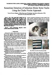
A general classification of the variable frequency IM control methods is presented in figure 2.1 [36]. These methods can be divided into two groups: scalar and vector control.
Fig 2.1 General classification of induction motor control method
2.2 The Scalar Speed Control Methods Stator voltage control. Frequency control. Stator voltage and frequency control i.e. Volts per Hertz control [37]. 11
CHAPTER 2
SPEED CONTROL OF INDUCTION MOTORS
2.2.1 Scalar Control Method strategy The scalar control method is based on varying two parameters simultaneously. The speed can be varied by increasing or decreasing the supply frequency, but this results in change of impedances. The change of impedances eventuates the increase or decrease of current. If the current is small, the torque of motor decreases. If the frequency decreases or the voltage increases, the coils can be burned or saturation can occur in the iron of coils. To avoid these problems, it is necessary to vary the frequency and the voltage at the same time. In this way, the occurring disadvantages of changing frequency and voltage can be compensated. According to the equation of induced voltage the V/Hz constant control gives constant flux in the stator equation (2.3). [38]. 𝐸𝑆 𝑓
= 4.44 . 𝑁 . 𝜓𝑠 . 𝜉
(2.3)
Where: 𝐸𝑆 : The stator induced voltage in the stator windings. 𝑓 : The frequency of the supplied voltage. 𝑁 : The number of turns for the stator windings. 𝜓𝑠 : Magnetic flux-linkage in the stator. 𝜉 : Winding factor. The torque–speed equation of induction motors can be used determine the voltage–torque and frequency–torque functions [39].
𝑇𝑒 =
3 2𝜔𝑚
𝐼𝑟2
𝑅𝑟
to
(2.4)
𝑠
where: 𝑇𝑒 𝜔𝑚 𝐼𝑟 𝑅𝑟 s
: The torque of the motor in the air-gap. : The mechanical angular speed. : The rotor current. : The resistance of rotor. : The motor slip.
It can be seen from equation (2.4) that the relationship between torque and frequncy is inversely proportional, while voltage is directly proportional to torque.Torque speed control can be solved by the linear variation of the two parameters. 𝑇𝑒 𝜔
~
𝑉2 2𝜋𝑓
2~
𝑉
(2.5)
𝑓
With this control method the torque is accessible inall operating points up 12
CHAPTER 2
SPEED CONTROL OF INDUCTION MOTORS
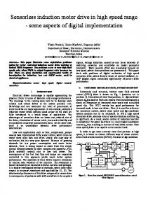
to the nominal value of speed and the motor can operate over the nominal speed. In the over speed range, the torque of the motor will decrease in inverse proportional to the increasing frequency as shown in figure 2.2, because voltage cannot be haigher than the value at which the driver electronics is able to operate [40].
Fig 2.2 Torque speed characteristic at constant flux In scaler control there is an inherent coupling effect, because both torque and flux are functions of voltage or current and frequency. This results in sluggish response and is prone to instability because of 5th order harmonics [41]. The performance of the v/f control is not satisfactory, because the rate of change of voltage and frequency has to be low. A sudden acceleration or deceleration of the voltage and frequency can cause a transient change in the current, which can result in drastic problems.
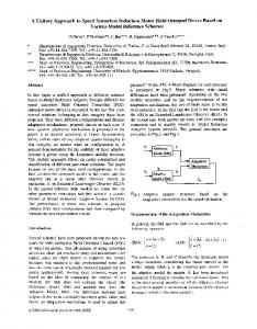
2.2.2 Scalar Control Classification 1-Open loop Scalar control. 2- Closed loop Scalar control. 2.2.2.1 Open-loop scalar control The open-loop Volts/Hertz control of induction motors is widely used in industry. For this strategy, feedback signals are not required. This type of motor control which illustrated in figure 2.3 has some advantages: Low cost. Simplicity. Immunity to errors of feedback signals. 13
CHAPTER 2
SPEED CONTROL OF INDUCTION MOTORS
Fig 2.3 Open-loop V/Hz constant control Some problems encountered in the operation of this open loop drive are the following [8]: The speed of the motor cannot be controlled precisely, because the rotor speed will be slightly less than the synchronous speed and that in this scheme the stator frequency and hence the synchronous speed is the only control variable. The slip speed, being the difference between the synchronous speed and the electrical rotor speed, cannot be maintained, as the rotor speed is not measured in this scheme. However, the frequency (or synchronous speed) is not the real speed because of a slip is function of the motor load. This can lead to operation in the unstable region of the torque-speed characteristics. The effect of the above can make the stator currents exceed the rated current by a large amount thus endangering the inverterconverter combination. The main disadvantage of this method it doesn't control the torque so the desired torque is only accessible at the nominal operating point [38]. This type of drive is suitable for applications such as pumps and fans, which do not require high levels of accuracy or precision. To overcome these problems, the induction motor drive must has an outer loop in which the actual speed of the rotor is compared with its desired value, and the error is processed through a controller such as PI controller. Also there is a limiter to obtain the slip-speed command. 2.2.2.2 Closed-loop scalar control The closed-loop technique controls the torque as presented in figure 2.4. If the load torque changes, the speed of the motor will change, too [42]. The closed-loop method contains a slip control loop, because the slip is 14
CHAPTER 2
SPEED CONTROL OF INDUCTION MOTORS
proportional to the torque. Since slip is proportional to torque at constant flux, this approach may be considered as open loop torque control within a speed control loop. The speed feedback signal from the tachogenerator is compared to the desired speed value. The difference between the speed feedback and the desired speed value is decreased to zero by the PI controller, so the motor will reach the desired speed. Typical applications of this method are in the winder drives [43]. A disadvantage of the method is uncontrolled magnetic flux. Closed loop v/f control is more precise than the open loop method.
Fig 2.4 Closed-loop V/Hz constant control From the above mentioned, scalar Control is the most popular and has found widespread use in industrial and domestic applications because of its ease-of-implementation. However, it has inferior dynamic performance compared to vector control. Thus, in areas where precision is required, V/f Control are not used.
2.2.3 Features of Scalar Control Scalar control has the following main advantages: Simplicity. Reliability. Requires a minimum of information about the engine. No need to use a rotor position sensor. Common disadvantages of scalar control systems: Impossible to control the motor torque under transient conditions. Reduced speed. Big error. 15
CHAPTER 2
SPEED CONTROL OF INDUCTION MOTORS
The vector control is a better solution so that it controls flux and torque independent of each other and the induction motor is transformed from non-linear to liner control plant [44].
2.3 Vector control method It is known that if the flux linkage of the rotor of the induction motor is fixed in special frame, the electromagnetic torque will behave similar to the separately excited DC motor. In the Vector Control method like the separately excited DC motor it is possible to decouple the flux control and the torque is thereby opened up. The field orientation control of induction motor allows decoupling the control of magnetic flux and the control of the torque produced by the stator current. This makes the induction motor control more akin to the control of the separately excited DC motor. That is, in three phase induction motor control, the rotor field can be equivalent to the field of excitation of dc motor, but with the difference that the voltage in the rotor, which produces the field, is dependent on the magnetic field in the stator [45]. Field oriented control is one of the vector control methods. There are other well-known methods like direct torque control and direct self-control that work with vectors, as well [38].
2.3.1 Algorithm of vector control Traditionally, induction motors have been run at a single speed, which was determined by the frequency of the main voltage and the number of poles in the motor. Controlling the speed of an induction motor is far more difficult than controlling the speed of a DC motor since there is no linear relationship between the motor current and the resulting torque as there is for a DC motor [34]. Vector control can be used to vary the speed of an induction motor over a wide range. It was initially developed by Blaschke (1971-1973) [46], [47], [48]. In the vector control scheme, a complex current is synthesized from two quadrature components, one of which is responsible for the flux level in the motor, and another which controls the torque production in the motor. Essentially, the control problem is reformulated to resemble the control of a DC motor. Vector control offers a number of benefits including speed control over a wide range, precise speed regulation, fast dynamic response, and operation above base speed. The vector control algorithm is based on two fundamental ideas. The first is the flux and torque producing currents. The induction motor can be modelled most simply (and controlled most simply) using two quadrature currents rather than the familiar three phase 16
CHAPTER 2
SPEED CONTROL OF INDUCTION MOTORS
currents actually applied to the motor. These two currents called direct (𝐼𝑑 ) and quadrature (𝐼𝑞 ) are responsible for producing flux and torque respectively in the motor. Of course, the actual voltages applied to the motor and the resulting currents are in the familiar three-phase system. The transformation between a stationary reference frame and a reference frame, which is rotating synchronous with the stator flux, becomes then the problem. This leads to the second fundamental idea behind vector control. The second fundamental idea is that of reference frames. The idea of a reference frame is to transform a quantity that is sinusoidal in one reference frame, to a constant value in a reference frame, which is rotating at the same frequency. Once a sinusoidal quantity is transformed to a constant value by careful choice of reference frame, it becomes possible to control that quantity with traditional proportional integral (PI) controllers. The field oriented control ensures good and robust control in case of transients. Field oriented control is based on a mathematical abstraction. This results in an easier model conformation which corresponds the structure of well-controllable DC machine. The principle of field oriented control works with rotating vectors (or phasors) in a complex coordinate system. The magnitude and the phase of the controlled current change. With this technique, it is possible to uncouple the field components. Uncoupling establishes two independent and single controlled currents: the flux- producing current and the torqueproducing current. Using these currents, the flux and torque can be independently controlled. Moreover, a 90° electric angle is ensured between the uncoupled control currents. As a result, the model of the induction motor loses its complexity, and a high-performance drive can be realized [49]. Field oriented control can be carried out by system and coordinate transformations of the basic equations of the motor. After applying the transformations, the alternating and sinusoidal quantities become non-alternating quantities. Due to uncoupling, the currents can be controlled, and then, after back-transformation it is possible to modify the output of the inverter with three-phase quantities. In this way, the magnitude and phase of supplied voltage or current can be modified. The quantities of the motor are described with a space phasor or a Park-vector in a three-phase coordinate system [50]. The control of DC drive is simple and has wide speed range. The simplicity of its control because of the decoupling between flux and torque. By looking to the figure 2.5 which represents a simple model of separately excited dc motor, the field circuit is shown as two poles pointed as N and S. The armature circuit represented as two brushes which connect the 17
CHAPTER 2
SPEED CONTROL OF INDUCTION MOTORS
current to the coils in the armature. The field space vector 𝜓𝑓 is produced by the stator poles which is on the same line with the direct axis. The position of the brushes (armature current flow) which is aligned with the quadrature axis and shifted by the vector of stator field by 90° although the rotor is rotating. It is known that the electromagnetic torque depends on the stator field 𝜓𝑓 and the armature current 𝑖𝑎 and the sin the angle between them. Thus, the maximum torque can be best achieved if two components, 𝜓𝑓 and 𝑖𝑎 , are spatially orthogonal [10].
Fig 2.5 Simple representation of separately excited DC motor Due to the fact that 𝜓𝑓 which is produced by the field current 𝐼𝑓 , and the armature current 𝐼𝑎 are flowing in different winding, so they can be separately controlled. Generating the optimal torque is not the only advantage of dc motor, but the magnetic field and the torque are controlled separately and that is called decoupling. For the latter reason, Vector Control method is known as decoupling control and the torque equation which can be used 43]. 𝑇𝑒 = 𝑘 𝑇 . 𝜓𝑓 ∙ 𝐼𝑎 = 𝑘. 𝐼𝑎 . 𝐼𝑓
(2.6)
Where: 𝐾𝑇 : a constant proportional with the motor’s size. 𝐼𝑎 : armature current. 𝐼𝑓 : field current. 𝜓𝑓 : field flux. The field flux 𝜓𝑓 produced by field current 𝐼𝑓 is orthogonal to the armature flux 𝜓𝑎 produced by the armature current 𝐼𝑎 as shown in figure 2.6. Because 𝜓𝑓 and ψ𝑎 are orthogonal, they are decoupled, i.e. the field
18
CHAPTER 2
SPEED CONTROL OF INDUCTION MOTORS
current only controls the field flux and the armature current only controls the armature flux [50].
Fig 2.6 Separately excited DC motor The control of induction motor can be similar to that of DC motor if we could represent the induction motor by two orthogonal components of current in a synchronously rotating reference frame (SRRF), one of these two components control the flux and the other control the torque of the machine. This strategy can be achieved with vector control of induction motors.
2.3.2 Strategy of Vector Control of Induction Motor Drive To perform the vector control technique, it's necessary to decompose the stator current phasor into two orthogonal components in a synchronously rotating reference frame and this requires two transformations: 1- Clarke Transformation. 2- Park Transformation. 2.3.2.1 Vector transforms The Park and Clarke vector transforms are one of the keys to vector control of induction motors. 1) Clarke transform The forward Clarke (1943) [51] transform does a magnitude invariant translation from a three-phase system into two orthogonal components. If the neutral - ground connection is neglected, the variables in a three-phase system (A, B, and C) sum is equal to zero, and there is a redundant information. Therefore, the system can be reduced to two variables, called 𝛼 and 𝛽. The Clarke transform is given by: [𝑖𝑖𝑠𝛼(𝑡) ] 𝑠𝛽 (𝑡)
1 cos(𝛾) = ∙[ 3 0 sin(𝛾) 2
𝑖𝐴𝑠 (𝑡) cos(2𝛾) ] ∙ [𝑖𝐵𝑠 (𝑡)] sin(2𝛾) 𝑖𝐶𝑠 (𝑡) 19
(2.7)
CHAPTER 2
SPEED CONTROL OF INDUCTION MOTORS
Where: 𝛾 =
2𝜋 3
,
Thus, the Clarke transform can be simplified to:
[𝑖𝑖𝑠𝛼(𝑡) ] = [1 (𝑡) 𝑠𝛽
√3
𝑖𝐴𝑠 (𝑡) ∙(𝑖𝐴𝑠 (𝑡)+2𝑖𝐵𝑠 (𝑡))
]
(2.8)
The Clarke transform can also be understood using a vector diagram as shown in figure 2.7. In the figure, A, B, and C are the axes of a three-phase system, each offset 120° from the other. α and 𝛽 are the axes of a twovariable system where α is chosen to be coincident with A. To perform the Clarke, transform of a three-variable system (𝑖𝑠𝑎 ,𝑖𝑠𝑏 ,𝑖𝑠𝑐 ), 𝑖𝛼 is equal to 𝑖𝑠𝑎 and 𝑖𝛽 is the scaled projection of 𝑖𝑠𝑏 and 𝑖𝑠𝑐 onto the 𝛽 axis. The scaling is necessary to preserve the signal magnitudes through the transform. b
-B
isa isc
isc + i
sb
i sb
C
isc
C
I
isb
isa
I
A
A
a
isa B
B
Fig 2.7 Clarke transformation The Clarke transform preserves the magnitude, and realize a quadrature between the current components. 2) Park transform The Park (1929) [52] transform is a vector rotation (decoupling between rotor flux and torque), which rotates a vector (defined by its quadrature components) through a specified angle. The Park transform function implements the following set of equations: 𝑖𝑠𝑑 cos(𝜃𝑒 ) [𝑖 ] = [ −sin(𝜃𝑒 ) 𝑠𝑞
𝑖𝑠𝛼 sin(𝜃𝑒 ) ] ∙ [𝑖 ] cos(𝜃𝑒 ) 𝑠𝛽
(2.9)
Where 𝜃𝑒 is the angle to rotate the vector through. A reverse vector rotation can be accomplished simply by changing the sign on the sin (𝜃𝑒 ) input value. The vector rotation is illustrated by figure 2.8. Some references 20
CHAPTER 2
SPEED CONTROL OF INDUCTION MOTORS
(Vas -1990, Novotny and Lipo - 1996) describe the Park transform as a combination of the Clark and Park transforms presented here [53], [54]. Breaking into a three-variable-to-two transform (i.e. the Clarke transform) and a vector rotation is done for efficiency of calculation: with separate Park and Clarke transforms, only two trigonometric calculations are required as equation (2.9) in the traditional Park transform.
Fig 2.8 Principles of vector control
2.4 Field orientation control (FOC) Vector control techniques have made possible the application of induction motors for high performance applications where traditionally only DC drives were applied (Holtz - 1995) [55]. The procedure of controlling the induction motor using field orientation involves important mathematical transformations: 1. The developed torque and the flux 𝑇𝑒∗ , 𝜓𝑓∗ should be set at reference value and then the corresponding 𝑖𝑑𝑠 and 𝑖𝑞𝑠 in synchronous reference frame are found. 2. Angular position 𝜃𝑒 is then found to be used in the transformation from the synchronous reference frame to the stationary frame (𝑑𝑞 → 𝛼𝛽) to achieve desired 𝑖𝛼 and 𝑖𝛽 as shown in figure 2.9. 3. The last step is to convert the stator current in stationary reference frame to the desired three phase currents to be the base of control the inverter [56], [57].
Fig 2.9 Position of the rotor flux vector 21
CHAPTER 2
SPEED CONTROL OF INDUCTION MOTORS
The basic conceptual implementation of Field orientation control (FOC) is illustrated in the figure 2.10 [58]:
Fig 2.10 Field oriented control implementation principle with machine 𝒅 − 𝒒 model Fundamental requirements for the FOC are the knowledge of two currents (if the induction motor is star connected) and the rotor flux position. Knowledge of the rotor flux position is the core of the FOC. In fact, if there is an error in this variable the rotor flux is not aligned with daxis and the current components are incorrectly estimated. In the induction machine the rotor speed is not equal to the rotor flux speed (there is a slip speed; as such, a special method to calculate the rotor flux position (angle) is needed. The basic method is the use of the current model. Thanks to FOC it becomes possible to control, directly and separately, the torque and flux of the induction motors. Field oriented controlled induction machines obtain every DC machine advantage: instantaneous control of the separate quantities allowing accurate transient and steady state management [34].
2.4.1 Methods of Field Orientation Control (FOC) There are two general methods of field oriented control. One, called the direct or feed- back method, was invented by Blaschke [59], and the other, known as the indirect or feed forward method was invented by Hasse [60], [61]. The way of determining the angle (position) of the rotor flux vector, rotating at the synchronous speed, depends on the type of the field orientation. 22
CHAPTER 2
SPEED CONTROL OF INDUCTION MOTORS
2.4.1.1 Direct Field Orientation Method (DFO) When the identification of the flux vector is done by direct Hall effect sensor measurement or even indirectly by estimation of other motor electrical variables by the terminal voltages & currents directly by using flux estimators [62], it is called direct field orientation. This method depends on measuring the air gap flux using special sensor is called HallEffect-Device. Proportional Integral (PI) controller is used in both the flux and the torque loops to get the desired direct and quadrature components of the stator current in the synchronous reference frame. Those are then transformed to the same component in the stationary frame. Finally, the equations of control are referenced to the three phase motor drive currents to control the inverter operating conditions [43]. For DFOC an estimator or observer calculates the rotor flux angle 𝜃𝑒 [33]. Inputs to the estimator or observer are stator voltages and currents. An example of the DFOC system is presented in figure 2.11.
Fig 2.11 Block diagram of the Direct Field Oriented Control (DFOC) Practically, this kind of sensor and its position can decrease the degree of ruggedness of the induction motor. Direct field orientated control also called flux feedback control, is a method in which the required information regarding the rotor flux vector (magnitude and alignment) is obtained by means of direct flux measurement of estimation [44]. Direct flux measurement is achieved 23
CHAPTER 2
SPEED CONTROL OF INDUCTION MOTORS
using Hall sensors or flux sense winding [58]. Figure 2.12 presents the phasor diagram of DFOC.
Fig 2.12 Direct Field Orientation control (phasor diagram) The major disadvantage of this method is the need of number of sensors which has Significant cost and fixing up of flux sensors becomes a tedious job. Problems such as drift because of temperature, poor flux sensing at lower speed also persist [44]. All of these problems leads to the use of indirect field oriented control. 2.4.1.2 Indirect Field Orientation Method (IFO) The rotor flux angle 𝜃𝑒 is obtained from reference 𝐼𝑠𝑑 , 𝐼𝑠𝑞 currents. The angular speed of the rotor flux vector speed can be calculated as follows:
𝜔𝑒 = 𝜔𝑠𝑙 + 𝜔𝑟
(2.10)
Where 𝜔𝑠𝑙 is a slip angular speed. It can be calculated from [33]:
𝜔𝑠𝑙 =
𝐿𝑀 𝜓𝑟
∙
𝑅𝑟 𝐿𝑟
∙ 𝐼𝑠𝑞
(2.11)
Where; 𝜔𝑠𝑙 : The slip difference between 𝜔𝑒 &𝜔𝑟 . 𝐿𝑀 : The mutual inductance. 𝐿𝑟 : The rotor inductance. 24
CHAPTER 2
SPEED CONTROL OF INDUCTION MOTORS
𝑅𝑟 : The rotor resistance. 𝜓𝑟 : The rotor flux. 𝐼𝑠𝑞 : The stator current in q-axis. In figure 2.13 a block diagram of the IFOC is shown.
Fig 2.13 Block diagram of the Indirect Field Oriented Control (IFOC) The indirect estimation schemes of the rotor flux position ensure a good behavior in all speed range, and they are the common solution in practice [63]. In the indirect direct field, orientated control technique, the rotor flux vector position is computed from the speed feedback signal of the motor [44]. Figure 2.14 shows the phasor diagram of IFOC.
25
CHAPTER 2
SPEED CONTROL OF INDUCTION MOTORS
Fig 2.14 Indirect Field orientation control (phasor diagram) In the indirect direct field oriented control method, the rotor field angle and thus the unit vectors are indirectly obtained by summation of the rotor speed and slip frequency [64]. 𝜔𝑒 = 𝜔𝑟 + 𝜔𝑠𝑙
(2.12)
𝜃𝑒 = ∫ 𝜔𝑒 𝑑𝑡
(2.13)
𝜃𝑒 = 𝜃𝑟 + 𝜃𝑠𝑙
(2.14)
Where; 𝜔𝑒 : Synchronous speed which the de-qe frame is rotating at with respect to the stationary reference frame ds-qs 𝜃𝑒 : The angular position of the de axis with respect to the ds axis. 𝜔𝑟 : The measured rotor speed. 𝜔𝑠𝑙 : The slip difference between 𝜔𝑒 &𝜔𝑟 . 𝜃𝑟 : The angular position of the rotor. 𝜃𝑠𝑙 : The slip difference between 𝜃𝑒 &𝜃𝑟 .
2.4.2 The property of the FOC methods [33] The method is based on the analogy to control of a DC motor. FOC method does not guarantee an exact decoupling of the torque and flux control in dynamic and steady state operation. Relationship between regulated value and control variables is linear only for constant rotor flux amplitude.
26
CHAPTER 2
SPEED CONTROL OF INDUCTION MOTORS
Full information about motor state variable and load torque is required (the method is very sensitive to rotor time constant). Current controllers are required. Coordinate transformations are required. A PWM technique is required (it guarantees constant switching frequency). In the DFOC rotor flux estimator is required. In the IFOC mechanical speed is required. The stator currents are sinusoidal except of high frequency switching harmonics.
2.4.3 A few of the salient features of FOC FOC has the following main advantages [58]: The frequency 𝜔𝑒 of the drive is not controlled (as in scalar control). The motor is “self-controlled” by using the unit vector to help control the frequency and phase. There is no concern about instability because limiting 𝐼𝑠^ within the safe limit automatically limits operation to the stable region. Transient response will be fast because torque control by 𝑖𝑞𝑠 does not affect flux. Allows for speed control in all four quadrants (without additional control elements) since negative torque is directly taken care of in vector control. Disadvantages of FOC [65]: Requirement of two co-ordinate transformations. Requirement of current controllers. Requirement of high machine parameter sensitivity.
2.5 Direct Torque Control (DTC) More than a decade ago, direct torque control (DTC) was introduced to give a fast and good dynamic torque response and can be considered as an alternative to the field oriented control (FOC) technique [66], [67]. The configuration is much simpler than the FOC system due to the absence of frame transformer. It also does not need pulse width modulator and position encoder, which introduce delays and requires mechanical transducers respectively. It was introduced in 1986 [66]. With vector control method for induction motor operation, the magnitude and the phase of stator voltage can be controlled. Direct torque 27
CHAPTER 2
SPEED CONTROL OF INDUCTION MOTORS
control (DTC) is one method used in variable frequency drives to control the torque (and thus finally the speed) of three-phase AC electric motors. This involves calculating and estimate of the motor's magnetic flux and torque based on the measured voltage and current of the motor. Direct torque control has a very fast response and simple structure which makes it to be more popular used in industrial world [10]. The method proposed to replace the de-coupling control with the bangbang control, which meets very well with on–off operation of the inverter semiconductor power devices is referred to as direct torque control (DTC) [66]. The DTC also exploits the vector relationships but replaces the coordinate transformation concept of standard vector control with a form of bang - bang action, dispensing from pulse width modulation (PWM) current control [68]. In DTC, the bang-bang or hysteresis controllers impose the time duration of the active voltage vectors, moving stator flux along the reference trajectory. The key features of DTC compared to standard field oriented control includes [69]:
No current loops so current not directly regulated. Coordinate transformations not required. No separate voltage pulse width modulator. Stator flux vector and torque estimation required.
Starting with a few basics in a variable speed drive the basic function is to control the flow of energy from the mains to a process via the shaft of a motor. Two physical quantities describe the state of the shaft: torque and speed. Controlling the flow of energy depends on controlling these quantities. In practice one of them is controlled and we speak of "torque control" or "speed control". When a variable speed drive operates in torque control mode the speed is determined by the load. Torque is a function of the actual current and actual flux in the machine. Likewise, when operated in speed control the torque is determined by the load. Variable speed drives are used in all industries to control precisely the speed of electric motors driving loads ranging from pumps and fans to complex drives on paper machines rolling mills cranes and similar drives. The idea is that motor flux and torque are used as primary control variables which is contrary to the way in which traditional AC drives control input frequency and voltage, but is in principle similar to what is done with a DC drive, where it is much more straightforward to achieve. In contrast, traditional PWM and flux vector drives use output voltage and output frequency as the primary control variables but these need to be pulse width modulated before being applied to the motor. This modulator stage adds to 28
CHAPTER 2
SPEED CONTROL OF INDUCTION MOTORS
the signal processing time and therefore limits the level of torque and speed response time possible from the PWM drive. In contrast, by controlling motor torque directly, DTC provides dynamic speed accuracy equivalent to closed loop AC and DC systems and torque response times that are 10 times faster. The basic structure of direct torque and stator flux vector control is presented in figure 2.15.
Fig 2.15 Block diagram of the Direct Torque Control of Induction motor In DTC field orientation is achieved without feedback using advanced motor theory to calculate the motor torque directly and stator flux without using a modulator or a requirement for a tachogenerator or position encoder to feed back the speed or position of the motor shaft. A DSP (digital signal processor) is used together with ASIC (Application-specific integrated circuit) hardware to determine the switching logic of the inverter. The motor model is programmed with information about the motor, which enables it to determine parameters including stator resistance, mutual inductance saturation coefficients and motor inertia. The model also encompasses temperature compensation, which is essential for good static speed accuracy without encoder. DTC can withstand sudden load transients caused by the process, without any overvoltage or overcurrent trip [32]. 29
CHAPTER 2
SPEED CONTROL OF INDUCTION MOTORS
2.5.1 History of DTC DTC was patented by Manfred Depenbrock in the US [70] and in Germany, [71] the latter patent having been filed on October 20, 1984, both patents having been termed direct self-control (DSC). However, Isao Takahashi and Toshihiko Noguchi described a similar control technique termed DTC in an IEEJ paper presented in September 1984 [72] and in an IEEE paper published in late 1986[66]. The DTC innovation is thus usually credited to all three individuals. The only difference between DTC and DSC is the shape of the path along which the flux vector is controlled, the former path being quasicircular whereas the latter is hexagonal such that the switching frequency of DTC is higher than DSC. DTC is accordingly aimed at low-to-mid power drives whereas DSC is usually used for higher power drives [73]. (For simplicity, the rest of the article only uses the term DTC). Since its mid-1980s introduction applications, DTC have been used to advantage because of its simplicity and very fast torque and flux control response for high performance induction motor (IM) drive applications. DTC was also studied in Baader's 1989 thesis, which provides a very good treatment of the subject [74]. The first major successful commercial DTC products, developed by ABB, involved traction applications late in the 1980s for German DE502 [75], [76] and DE10023 [77] diesel-electric locomotives [78] and the 1995 launch of the ACS600 drives family. ACS600 drives has since been replaced by ACS800 [79] and ACS880 drives [80]. Vas, [81] Tiitinen et al [67] and Nash [82] provide a good treatment of ACS600 and DTC. DTC has also been applied to three-phase grid side converter control [83], [84]. Grid side converter is identical in structure to the transistor inverter controlling the machine. Thus, it can in addition to rectifying AC to DC also feedback energy from the DC to the AC grid. Further, the waveform of the phase currents is very sinusoidal and power factor can be adjusted as desired. In the grid side converter DTC version, the grid is considered to be a big electric machine. DTC techniques for the interior permanent magnet synchronous machine (IPMSM) were introduced in the late 1990s [85] and synchronous reluctance motors (SynRM) in the 2010's [86]. DTC was applied to doubly fed machine control in the early 2000s [87]. Doubly-fed generators are commonly used in 1-3 MW wind turbine applications.
30
CHAPTER 2
SPEED CONTROL OF INDUCTION MOTORS
Given DTC's outstanding torque control performance, it was surprising that ABB's first servo drive family, the ACSM1, was only introduced in 2007[88]. From the end of 90's several papers have been published about DTC and its modifications such as space vector modulation, [89] which offers constant switching frequency. In light of the mid-2000s expiration of Depenbrock's key DTC patents, it may be that other companies than ABB have included features similar to DTC in their drives.
2.5.2 Direct Torque Control Strategy The principle of DTC for Induction motor drive is based on limit cycle control and it makes possible both quick torque response and high efficiency operation at the same time. Furthermore, the inverter is directly controlled by the algorithm, the instantaneous values of flux and torque are estimated from the stator voltages and currents in order to comparing with the command values. Residual results are used to determine the optimum inverter switch states through a look-up table to supply for induction motor. As a result, torque can be controlled directly i.e. a modulation technique for the inverter is not needed. The selection is made so as to restrict the errors of the flux and torque within the hysteresis bands and to obtain the fastest torque response and highest efficiency at every instant [66]. However, if the control is implemented on a digital system (which can be considered as a standard nowadays); the actual values of flux and torque could cross their boundaries too far [90], [91], which is based on an independent hysteresis control of flux and torque. The control variables flux and torque are expressed in terms of stator variables. So, the estimation and control of these variables becomes simple. The output of the controller determines the switch positions of the inverter which in turn accelerate or decelerate the stator flux. Hence the torque is changed at faster rate. At the same time flux controller tries to keep the operating flux around the reference value [82]. The main advantages of DTC are absence of coordinate transformation and current regulator absence of separate voltage modulation block. Common disadvantages of conventional DTC are a sluggish response (slow response) in both starts up and changes in either flux or torque, large and small errors in flux and torque are not distinguished. In other words, the same vectors are used during start up and step changes and during steady state. In order to overcome the mentioned drawbacks, there are different solutions, which can be classified as follows modification of the 31
CHAPTER 2
SPEED CONTROL OF INDUCTION MOTORS
switching table, so modified DTC (M_DTC) and twelve sectors DTC (12_DTC) [11].
2.5.3 The Basic Principles of Direct Torque Control of Induction Motor In the DTC scheme the electromagnetic torque and stator flux error signals are delivered to two hysteresis controllers as shown in figure 2.15. The stator flux controller imposes the time duration of the active voltage vectors, which move the stator flux along the reference trajectory, and the torque controller determinates the time duration of the zero voltage vectors, which keep the motor torque in the defined-by-hysteresis tolerance band. The corresponding output variables 𝑑 𝑇 , 𝑑𝜓 and the stator flux position sector 𝜃𝜓𝑠 are used to select the appropriate voltage vector from a switching table scheme (Takahashi & Noguchi, 1986), which generates pulses to control the power switches in the inverter. At every sampling time the voltage vector selection block chooses the inverter switching state, which reduces the instantaneous flux and torque errors [92]. In practice the hysteresis controllers are digitally implemented. This means that they function within discrete time 𝑇𝑠 . Consequently, the control of whether the torque or the flux is within the tolerance limits, often delays depending on the duration of the sampling period. This results in large ripples in the torque and the current of the motor. In conclusion, the abrupt and undesirable ripples in the electromagnetic quantities appear when the control of the values of the torque and the flux takes place at times when their values are near the allowed limits. This means that a voltage vector will be chosen which will continue to modify these quantities in a time 𝑇𝑠 , even though these limits have been practically achieved. Accordingly, in the next control which will be carried out after time 𝑇𝑠 , these quantities will be quite different from the desirable values. Another reason why the electromagnetic torque of the motor presents undesirable ripples is the position of the ⃗⃗⃗⃗ 𝜓𝑠 in each of the six sectors of its transition. In general, an undesired ripple of the torque is observed when the ⃗⃗⃗⃗ 𝜓𝑠 moves towards the limits of the cyclic sectors and generally during the sectors’ change. Furthermore, the torque ripple does not depend solely on the systems conditions but on the position of ⃗⃗⃗⃗ 𝜓𝑠 in the sector as well.
2.5.4 Basic principles of Switching Table The main concept for employing a switching table in DTC is that the estimated values of stator flux and electromagnetic torque are compared to 32
CHAPTER 2
SPEED CONTROL OF INDUCTION MOTORS
reference values, i.e. figure 2.17. 𝜓𝑠∗ and 𝑇𝑒∗ through what is called hysteresis controller figure 2.16. These two hysteresis controllers are different for Torque and flux. Because the flux and torque have to fall into a certain band for switching table DTC, we have two limits, which is considered as the tolerance number of allowing being “how far” from the desired value we can employ this method and still be accurate. In practice, the flux controller provides two cases (a two-level controller). In contrast to achieve the desired output torque the hysteretic controller need provide three separate cases. The equations 2.15 and 2.16 represent the hysteresis band limits for the flux tables and equations 2.17 through 2.19 represent the three levels hysteresis bands of the torque tables [93]. The output signals 𝑑𝜓 , 𝑑 𝑇 are defined as: 𝑑𝜓 𝑑𝜓 𝑑𝑇 𝑑𝑇 𝑑𝑇
= 1 , for = 0, for = 1, for = 0, for = −1, for
𝑒𝜓 > 𝑒𝜓 < 𝑒𝑇 > 𝑒𝑇 = 𝑒𝑇