Shape Recovery of 3D Data Obtained from a Moving Range Sensor by using ... propose a method to recover 3D range data obtained by a .... computer vision.
Shape Recovery of 3D Data Obtained from a Moving Range Sensor by using Image Sequences Atsuhiko Banno Katsushi Ikeuchi Institute of Industrial Science, The University of Tokyo, Japan {vanno, ki}@cvl.iis.u-tokyo.ac.jp
Abstract For a large object, scanning from the air is one of the most efficient methods of obtaining 3D data. But in the case of large cultural heritage objects, there are some difficulties in scanning with respect to safety and efficiency. To remedy these problems, we have been developing a novel 3D measurement system, the Floating Laser Range Sensor (FLRS), in which a range sensor is suspended beneath a balloon. The obtained data, however, have some distortion due to movement during the scanning process. In this paper, we propose a method to recover 3D range data obtained by a moving laser range sensor. This method is applicable not only to our FLRS, but also to a general moving range sensor. Using image sequences from a video camera mounted on the FLRS enables us to estimate the motion of the FLRS without any physical sensors such as gyros or GPS. In the first stage, the initial values of camera motion parameters are estimated by full-perspective factorization. The next stage refines camera motion parameters using the relationships between camera images and range data distortion. Finally, by using the refined parameters, the distorted range data are recovered. In addition, our method is applicable with an uncalibrated video camera and range sensor system. We applied this method to an actual scanning project, and the results showed the effectiveness of our method.
1. Introduction Recently there has been great progress in research on real object modeling because of the availability of accurate geometric data from three-dimensional digitizers. The techniques of real object modeling contribute to numerous applications in areas such as academic investigation, industrial management, and entertainment. Among them, one of the most important and comprehensive applications is modeling objects of valuable cultural heritage. Modeling these objects has led to digital archiving of their shapes and to restoration of the original shapes, even
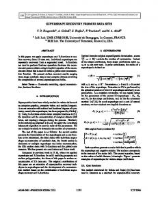
if the objects have been destroyed due to natural weathering, fire, disasters, and wars. We can provide images of these objects through the Internet to people in their homes or in their offices. Thus, the techniques of real object modeling are available for many applications. We have been conducting some projects to model large cultural heritage objects such as great Buddhas, historical buildings, and suburban landscapes[13][8]. To scan cultural objects, a laser range finder is usually positioned on a tripod placed on a stable location. When the object is very large, however, some part of the object is not visible from the laser range finder on the ground. To overcome this difficulty, we have scanned large objects from scaffolds temporally constructed near the object. However, this scaffold method requires costly, tedious construction time. In addition, it may be impossible to scan some parts of the object due to the limitation of available space for scaffold-building. We are now conducting a project to model the Bayon Temple in Cambodia. This temple is immense, measuring about 100 × 100 square meters. Scanning such a huge object from several scaffolds is unrealistic. To overcome this problem, several methods have been proposed. For example, aerial 3D measurements can be obtained by using a laser range sensor installed on a helicopter platform. High frequency vibration of the platform, however, can interfere with the accuracy of the results. And the use of heavy equipment such as a crane should be eschewed when scanning a cultural heritage object because of potential damage to the object. Based upon the above considerations, we proposed a novel 3D measurement system, a Floating Laser Range Sensor (FLRS)[7]. This system digitizes large objects from the air while suspended from the underside of a balloon platform (Fig.1). This platform is free from high frequency vibration such as that of a helicopter engine. However, the obtained range data are distorted because the laser range sensor itself is moving during the scanning processes. We could adopt three strategies to solve this problem: • Window matching-based method[6]
describe our proposed algorithm for refinement of the parameters. In Section 4, we describe how we use this algorithm to model and recover the shape of the Bayon Temple in Cambodia. To evaluate our method, the recovered shapes are compared with other data obtained by a range sensor on the ground. In Section 5, we explain a method in the uncalibrated system, in which the video camera is not calibrated with the range sensor. Finally, we present our conclusions and summarize our possible future work.
2. Previous Works Figure 1. The Floating Laser Range Sensor
• 3D registration-based method[12] • Structure from motion-based method In [6], under the assumption that translation of the balloon is within a plane parallel to the image plane without any rotation, we recover the correct shape by using a video sequence image and a correlation technique. This method is very fast, but it restricts the balloon to a simple motion. In [12], we apply an extended ICP algorithm to align the deformed model obtained by the FLRS to the correct model obtained by a range sensor located on the ground. This method does not require image sequences, but it requires a wide overlapped region between the two models. In this paper, we adopt the third strategy among the methods listed above, and we propose a method to recover accurate 3D range data obtained by a moving laser range sensor without any physical sensors such as gyros or GPS. This method is applicable to general motion and does not require any other correct data obtained by other range sensors. Moreover, this method is not limited to the case of our FLRS, but it is also applicable to a general moving range sensor that has smooth motion. We use distorted range data obtained by using the range sensor and image sequences obtained by using a video camera mounted on the FLRS. Firstly, the motion of the FLRS is estimated by the obtained images. Then we estimate the refined camera motion parameters imposing some constraints, which include information derived from the distorted range data itself. In order to solve the non-linear optimization problem, we utilize a full-perspective factorization method as the initial value to avoid local minimums. Finally, using the refined camera motion parameter, the distorted range data are recovered. This paper organized as follows. In the next section, a review of related works is presented. In Section 3, we describe our method to estimate camera motion. At first, we briefly explain the perspective factorization, which is utilized as the initial value for the camera motion. Then we
Estimations of the shape of an object or of camera motion by using images are called ”Shape from Motion” or ”Shape from Structure”, and are main research fields in computer vision. The factorization method proposed in [21] is one of the most effective algorithms for simultaneously recovering the shape of an object and the motion of the camera from an image sequence. By using singular value decomposition (SVD), the shape and motion are estimated from the trajectories of interest points. At first, this method was limited to the orthographic model. Then the factorization was extended to several perspective approximations and applications[2][14][16][4]. Among them, [16] based factorization methods on the weak-perspective (or scaled orthographic projection) model are proposed, in which the scaling effect of an object is accounted for as it moves toward and away from the camera. At the same time, it is applied under the para-perspective projection model, which is a better approximation of the perspective model than that of the weak-perspective model. In the para-perspective model, the scaling effect as well as the different angles from which an object is viewed are accounted for as the object moves in a direction parallel to the image plane. In [16], they also presented perspective refinement by using the solution under the para-perspective factorization as the initial value. In [4] a factorization method with a perspective camera model is proposed. Using the weak-perspective projection model, they iteratively estimated the shape and the camera motion under the perspective model. Besides the factorizations, many SFM algorithms have been developed in the last decade. In [18], they reconstruct 3D surface from uncalibrated image sequences. Stereo vision is one of the most traditional methods for recovering an object shape by using several images. In stereo vision, knowledge of the parameters of camera positions and poses enables recovery of the shape. In [10], [22] and [24], they estimated the rotation matrix and the translation vector from the essential matrix E. By using the eightpoint algorithm[5] and the five-point algorithm[15], the fundamental matrix F and the essential matrix E are estimated, respectively, only through images. Ambiguity of scaling,
however, remains in these methods. Recently, many researchers have used some sophisticated physical sensors, including gyros and GPS, to obtain the absolute scaling. In particular, when modeling large objects such as buildings and scenes, a great deal of research combining these sensors (sensor fusion) has been undertaken. In [26], they recovered camera poses and 3D structure of large objects by image sequences from the air by using motion stereo. Then the recovered shapes (3D point clouds) are registered to other correct 3D data, and texture images are mapped onto the 3D data.
3. Camera Motion Estimation 3.1. Full-Perspective Factorization Given a sequence of F images, in which we have tracked P interest points over all frames, each interest point p corresponds to a single point s~p on the object. In image coordinates, the trajectories of each interest point are denoted as {(uf p , vf p )|f = 1, ..., F, p = 1, ..., P 2F ≥ P }. Each frame f is taken at camera position t~f in the world coordinates. The camera pose is described by the orthonormal unit vectors i~f , j~f and k~f . The vectors i~f and j~f correspond to the x and y axes of the camera coordinates, while the vector k~f corresponds to the z axis along the direction perpendicular to the image plane (Fig.2).
vf p = f
j~f (s~p − t~f ) k~f (s~p − t~f )
(2)
displacing zf = −k~f t~f , we obtain the following equation. λf p uf p
=
λf p vf p
=
λf p
=
f ~ if (s~p − t~f ) zf f ~ jf (s~p − t~f ) zf k~f · s~p 1+ zf
(3) (4) (5)
Note that the right hand sides of eq.(3) and (4) are the same form under the weak-perspective model. This means, multiplying a image coordinate (uf p , vf p ) by a real number λf p changes coordinates under the perspective model into coordinates under the weak-perspective model. Solving the value of λf p iteratively, we can obtain motion parameters and coordinates of interest points under the perspective model in the framework of weak-perspective factorization. The entire algorithm of the perspective factorization is as follows: Input: An image sequence of F frames tracking P interest points. Output: The positions of P interest points s~p . The camera position t~f and poses i~f , j~f , k~f at each frame f. 1. giving λf p = 1 2. supposing the equations (3) and (4), solve s~p , t~f , i~f , j~f , k~f and zf using the weak perspective factorization. 3. calculate λf p by the equation (5). 4. substituting λf p into step2; repeat the above procedure until λf p ’s are close to the previous iteration.
3.2. Refinement of Camera Motion Figure 2. The Coordinate System: t~f denotes the position of the camera at time of frame f. The camera pose is determined by three unit basis vectors. Under the pinhole camera model, the projective equation between the object point s~p in 3D world and the image coordinate (uf p , vf p ) is written as uf p = f
i~f (s~p − t~f ) k~f (s~p − t~f )
(1)
Without noise in the input, the above factorization method leads to the excellent solution. As a result, the recovered 3D shape through the estimated camera parameters is valid. Real images, however, contain a bit of noise. Therefore, it is not sufficient to recover range data obtained by the FLRS only through the factorization. For the sake of a more refined estimation of camera parameters, we impose three constraints: tracking, movement, and range data. Refined camera motion can be found through the minimization of a global functional. To minimize the function, the solution by the perspective factorization is utilized as the initial value to avoid local minimums.
3.2.1 Tracking Constraint
3.2.3 Range Data Constraint
As the most fundamental constraint, any interest point s~p must be projected on each image plane at the coordinates (uf p , vf p ). This constraint conducts the following function (Bundle adjustment): Ã F P ³ ´ X X i~ (s~ − t~ ) 2
Taking a broad view of range data obtained by the FLRS, the data are distorted by the swing of the camera. We can find, however, that these data contain instantaneous precise information locally; that information is utilized for refinement of the camera motion. The laser range sensor re-radiates laser beams in raster scan order. This means that we can instantly obtain the time when each pixel in the range image is scanned. If the video camera coincides with the range sensor, we can find the exact frame among the sequence when the pixel is scanned. With the video camera calibrated with the range sensor, we can also obtain the image coordinate of each interest point in the 3D world, with the respect to the instantaneous local coordinate. Considering this constraint, we can compensate the camera motion. Then, we can conduct the third constraint to be minimized as follows:
FA =
uf p − f
f =1 p=1
³
f
p
f
k~f (s~p − t~f )
´ j~f (s~p − t~f ) 2 + vf p − f k~f (s~p − t~f )
! (6)
The minimization of FA leads to the correct tracking of fixed interest points by a moving camera. However, we can see that the presence of parameters we are trying to estimate in the denominator makes this equation a difficult one. Then, suppose that instead, we consider the following function: Ã F P ³ ´2 X X k~f (s~p − t~f )uf p − f i~f (s~p − t~f )
FA =
f =1 p=1
³
+ k~f (s~p − t~f )vf p − f j~f (s~p − t~f )
´2
! (7)
3.2.2 Movement Constraint One of the most significant reasons for adopting a balloon platform is to be free from the high frequency that occurs with a helicopter platform. A balloon platform is only under the influence of low frequency: the balloon of our FLRS is held with some wires swayed only by wind. This means that the movement of the balloon is expected to be smooth. Certainly, the movement of the balloon is free from rapid acceleration, rapid deceleration, or acute course changing. Taking this fact into account, we consider following function: Z µ ³ 2 ~ ´2 ³ ∂ 2 q ´2 ¶ ∂ tf f FB = w1 + w dt (8) 2 ∂t2 ∂t2 Here, t~f denotes the position of the camera; t is time; w1 , w2 are weighted coefficients; and qf is a unit quaternion that represents the rotation of the camera pose. The presentation by quaternion is obtained immediately by i~f , j~f and k~f . The first term of the above integrand represents smoothness with respect to the camera’s translation while the second represents smoothness with respect to the camera’s rotation. When the motion of the camera is smooth, the function FB becomes a small value. We implement in practice the following discrete form: ! Ã F ³ ∂ 2 q ´2 ³ ∂ 2 t~ ´2 X f f + w2 (9) FB = w1 ∂t2 ∂t2 f =1
FC =
P X ° ° ° xf p − RT (s~p − t~f p ) °2
(10)
p=1
Here, the index f p denotes the frame number when the range sensor scans the interest point p, and the measured distance by the range sensor at this moment denotes xf p . As xf p = (xf p , yf p , zf p ), the above function can be rewritten: FC
=
P ³ X ¡
xf p − i~f p (s~p − t~f p )
¢2
p=1
+
¡
¢2
yf p − j~f p (s~p − t~f p )
¡
¢2 ´
+ zf p − k~f p (s~p − t~f p )
(11)
3.2.4 The Global Cost Function The weighted sum F = wA FA + wB FB + wC FC
(12)
leads to a global function. To minimize this function, we employ the Fletcher-Reeves method and the Polak-Ribiere method[17][9][19], which are types of the conjugate gradient method. Then, we use the golden section search to determine the magnitude of gradient directions. As mentioned in the previous sections, we input the solution by the perspective factorization as the initial value. Minimizing the function F is basically quite difficult because this function has many local minimums. By employing the solution of the factorization as a fairly good approximation, we try to avoid them.
4. Experiments We measured the Bayon temple in Cambodia by using our balloon platform. Large parts of the temple that are visible from the ground were scanned by range sensors placed on the ground. Some parts invisible from the ground, for example, roofs and tops of towers, were scanned by our FLRS system. In our system, we obtain 72 frames at a single scanning process. For interest point tracking, we use the SIFT key[11], which is robust for scaling, that is, a movement along the view direction. A simple 128-dimensional matching in SIFT key traced the trajectory of each point throughout all the frames. After this procedure, we can derive about one hundred interest points from a sequence of 72 frames. The result is shown in Fig.3. The model in Fig.3(a) is the original data obtained from the FLRS. The motion of the balloon was so wide that the model wass deformed widely. In Fig.3(b), the recovered model by full-perspective factorization is shown. With respect to motion parameters, the ambiguity in scale is removed manually in this model. At a glance, the factorization seems to recover the shape properly. In detail, however, the distortion in S shape is still left. Especially, the shape of the entrance is skewed. On the other hand, Fig.3(c) shows the recovered data by our method. It is clear that the distortion in S shape is removed and the shape of the entrance is correctly recovered into a rectangle. To verify the accuracy of our shape recovery algorithm, we compared the recovered shape with other data that were obtained by a range finder, the Cyrax2500, positioned on the ground. Aligning two data sets by using the ICP algorithm[1][25], we analyzed the overlapped area. The result is shown in Fig.4. Fig.4(a) shows a photo picture of the scanned area. In Fig.4(b), the dense fine data is nondistorted data(the correct data) obtained by the Cyrax2500. The coarse data, colored pink, indicates the data recovered by our method. One can easily see that the recovered 3D shape fits well onto the Cyrax2500’s data. This aligned models shows that our algorithm is effective. Figure 5 also shows the effectiveness of the method. The figure indicates the point-to-point distances in the ICP algorithm between the Cyrax2500’s data and the recovered data. Fig.5(a) shows a comparison between the Cyrax2500’s and the original distorted data, Fig.5(b) shows a comparison between the Cyrax2500’s and the recovered data by fullperspective factorization, and Fig.5(c) shows a comparison between the Cyrax2500’s data and the data recovered by our method. The region where the distances between them are less than 6.0 cm is colored green, indicating a correct mathematical correspondence. The area where the distances are farther than 6.0 cm is displayed in blue. One can see that the green region is clearly expanded by our recovery algorithm, indicating that the method can recover the 3D shape
Figure 4. (a):A photo of the measured area. (b):The correct range data obtained by the Cyrax 2500 on the ground and the recovered FLRS data by our method, which are alligned by an ICP algorithm.
correctly. Figure 6(a) shows the trace of camera’s translation obtained by full-perspective factorization, while Fig.6(b) shows the results after the refinement. The convergence in the factorization was not good, therefore, the curves in Fig.6(a) has jagged shapes, which are not acceptable for the balloon’s motion. On the other hand, the curves in Fig.6(b) are smooth and acceptable. This result shows that our refinement is effective in lessening the camera motion and leads to the correct motion estimation.
Figure 6. The trace of the camera translation: The curves show the parameters(x, y in the world coordinate) estimated by the perspective factorization(a), and by our proposed method(b). In (b), the camera motion becomes smooth and valid.
5. Uncalibrated System The method described above is based on a calibrated system, in which the relative positions are known between the range sensor-oriented coordinate system and the video
Figure 3. (a):The original distorted range data obtained by the FLRS. (b):The recoverd range data by the full-perspective factorization without ambiguity in scale. (c) The recoverd range data by our method.
Figure 5. The comparisons between the Cyrax2500’s data(the correct data) and (a) the original distorted data, (b) the initial recoverd data by the factorization and (c) the recoverd data by our proposed method: Each pair is alligned by an ICP algorithm. The green region indicates where the distance of corresponding point pair is less than the threshold(in this case 6.0 cm), that is, the match region. Note that the green region is expanded after the refinement in (c).
camera-oriented one. In this section, we describe how we applied our method to an uncalibrated system, in which the configuration between the two systems is unknown. At first, we reconstructed 3D scene with the ambiguity in scale from image sequences. Then we reconstructed 3D data deformed according to the estimated camera motion. The deformed 3D data with scale ambiguity are aligned to the 3D data obtained by the range sensor. This process removes the ambiguity, and determines the relationship between two coordinate systems. Finally, we applied the refinement method mentioned in the previous section and recovered the shape.
ibrated system, we can’t impose the Range Data Constraint in this stage. The estimated parameters are, therefore, refined only by the Tracking Constraints and the Movement Constraint with ambiguity in scale. The number of estimated 3D points is, unfortunately, small in the case of wide camera motion. It is difficult to align this sparse 3D model to the dense model obtained by a range sensor. To overcome this problem, we increase the number of tracked points. In the factorization, we utilize the points that are trackable over a sequence. In this process, we use other points that are visible over a certain number of frames. To estimate these re-registered 3D points, we use a Maximum Likelihood (ML) Estimation method.
5.1 Increment of Track Points ~sM L = max p(U |θ, ~s) At first, using the points visible from the whole sequence, sparse 3D points and camera motion parameters are estimated by the full-perspective factorization. In the uncal-
~ s
(13)
According to ML-Estimation, observed image points U have the maximum probability under the camera motion pa-
rameters θ and 3D points ~s. In our implementation, the Gaussian function is adopted as the noise model. We utilize these 3D points ~sM L as the initial value for the next refinement.
5.2 Refinement Next, we estimate the configuration between the cameraoriented coordinate system and the range sensor’s system. Using the initial values of camera parameters in the previous subsection, the camera rotation matrix R with respect to time f is represented as ¡ ¢ Rf = ~if ~jf ~kf (14)
Figure 7. (a):An example image from a sequence. (b):The original distorted range data. In this case, the camera motion was so wide that the range data were distorted widely.
Here, the configuration between the video camera and the range sensor is described by a rotation matrix Rintra and a translation vector ~tintra . Using scale factor s, the minimization of the next function (in the robust estimation framework[3]) leads to the estimation of the relation between two coordinates. min
P X
¡
log 1 +
p=1
°
zf2p ¢ 2σ 2
(15)
°
2 zf p =° sRf T (~sp − ~tf ) − Rintra ~x − ~tintra °
(16)
The first term in eq.(16) is the point cloud deformed according to the camera motion. The above function assumes a small value when the shape of a deformed cloud is aligned to the original range data ~x obtained from a moving range sensor. After the estimation of s, Rintra and ~tintra , we can utilize the Range Data Constraint in 3.2.3.
Figure 8. (a):The recovered shape. (b):The recovered data alligned with Cyrax 2500’s data.
6. Conclusions 5.3 Experiment Figure 7 shows a sample image from a sequence (Fig.7(a)) and the original distorted range data with uncalibrated system. We can easily find that the 3D shape (Fig.7(b)) is distorted widely. In this case, the movement of the camera is too radical to track a sufficient number of points. Only 18 interest points are visible in whole sequence. The procedure of track point increment, however, increased the number and re-registered a total of 2431 points. After estimating the relation between the video camera and the range sensor, we estimate the refined motion parameters by the method mentioned in 3.2. Figure 8(a) shows the recovered shape by our method. Some distorted parts are left in detail on this model. The overall shape, however, is proper compared with Fig.7(b). The recovered shape is aligned with the correct data obtained by another sensor fixed on the ground. The result is shown in Fig.8(b). It is found that the recovered shape is fitted to the correct data. Thus, in an uncalibrated system, our method can recover the shape.
We have presented a method for estimating camera motion in conjunction with our efforts to estimate the shape of a large object. Correct motion estimation is essential to recover the object shape since, in our FLRS system, a range sensor swings during the measurement process. Using a video sequence on the FLRS and the distorted range data, we have estimated the camera motion. First, the fullperspective factorization derived the initial value for the estimation. Next, we solved a non-linear optimal problem under three constraints. In this process, we utilized distorted data which had been formerly sloughed. Finally, by using estimated camera motion parameters, we recovered the shapes. This method can be generally applied to a framework in which a range sensor moves during the scanning process, and is not limited to our FLRS because we impose only the smooth movement constraint. Our method is applicable to both calibrated and uncalibrated systems. Testing the method in an uncalibrated system by aligning distorted reconstructed 3D data from an image sequence with the range data obtained by a mov-
ing range sensor, we determined the relationship between the camera’s coordinate and the range sensor’s coordinate. Then we applied our method to a calibrated system. We achieved a certain level of accuracy for recovering the distorted range data, and our FLRS is expected to be effective for measurement of large objects. What remains to be done is to improve the precision obtained by this algorithm. Then we are going to extend our method to more general framework and more applications.
[11] D.G.Lowe, ”Distinctive image features from scale-invariant keypoints,” International Journal of Computer Vision, Vol.60, No.2, pp.91-110, 2004.
Acknowledgment
[14] T.Morita and T.Kanade, ”A sequential factorization method for recovering shape and motion from image streams,” IEEE Trans. on PAMI, vol.19, No.8, pp.858-867, 1997.
This work was supported in part by Ministry of Education, Culture, Sports, Science and Technology, under the program, ”Development of High Fidelity Digitization Software for Large-Scale and Intangible Cultural Assets” and Research Fellowships of Japan Society for the Promotion of Science(JSPS) for Young Scientists. Scanning the Bayon Temple was conducted jointly with Japanese Government Team for Safeguarding Angkor(JSA).
References [1] P.J.Besl and N.D.McKay, ”A method for registration of 3-D shapes,” IEEE Trans. on PAMI, vol.14, pp.239-256, 1992. [2] J.Costeira and T.Kanade, ”A multi-body factorization method for motion analysis,” Proc. of ICCV, pp.1071-1076, 1995. [3] F.R.Hampel, E.M.Ronchetti, P.J.Rousseeuw and W.A.Stahel, Robust Statistics: The Approach Based on Influence Functions, John Wiley, 1986. [4] M.Han and T.Kanade, ”Perspective factorization methods for Euclidean reconstruction,” CMU-RI-TR-99-22, 1999. [5] R.I.Hartley, ”In denfence of the eight-point algorithm,” IEEE Trans. on PAMI, Vol.19, No.6, pp.580-593, 1997. [6] K.Hasegawa, Y.Hirota, K.Ogawara, R.Kurazume and K.Ikeuchi, ”Laser Range Sensor Suspended beneath Balloon -FLRS(Flying Laser Range Sensor)-,” MIRU 2004 Meeting on Image Recognition and Understanding, Vol.1, pp.739744, 2004 (in Japanese). [7] Y.Hirota, T.Masuda, R.Kurazume, K.Ogawara, K.Hasegawa and K.Ikeuchi, ”Flying Laser Range Finder and its data registration algorithm,” Proc. of ICRA, pp.3155-3160, 2004. [8] K.Ikeuchi, A.Nakazawa, K.Hasegawa and T.Ohishi, ”The Great Buddha Project: Modeling Cultural Heritage for VR Systems through Observation,” The second IEEE and ACM International Symposium on Mixed and Augmented Reality(ISMAR2003), 2003 [9] D. A. Jacobs, The State of the Art in Numerical Analysis, London: Academic Press, 1977. [10] H.C.Longuet-Higgins, ”A computer algorithm for reconstructing a scene from two projections,” Nature, Vol.293, pp.133-135, 1981.
[12] T.Masuda, Y.Hirota, K.Nishino and K.Ikeuchi, ”Simultaneous determination of registration and deformation parameters among 3D range images,” Proc. of 3DIM, 2005. [13] D.Miyazaki, T.Oishi, T.Nishikawa, R.Sagawa, K.Nishino, T.Tomomatsu, Y.Takase and K.Ikeuchi ”The great buddha project: Modelling cultural heritage through observation,” Proc. of VSMM, pp.138-145, 2000.
[15] D. Nister, ”An efficient solution to the five-point relative pose problem,” Proc. of CVPR, Vol.2, pp.195-202, 2003. [16] C.Poelmann and T.Kanade ”A paraperspective factorization method for shape and motion recovery,” IEEE Trans. on PAMI, vol.19, No.3, pp.206-218, 1997. [17] E. Polak, Computational Methods in Optimization, New York: Academic Press, 1971. [18] M.Pollefeys, R.Koch and L.V.Gool, ”Self-calibration and metric reconstruction in spite of varying and unknown intrinsic camera parameters,” International Journal of Computer Vision, Vol.32, No.1, pp.7-25, 1999. [19] J. Stoer and R.Bulirsh, Introduction to Numerical Analysis, New York: Springer-Verlag, 1980. [20] S.Thrun, M.Diel and D.Haehnel, ”Scan alignment and 3-D surface modeling with a helicopter platform,” The 4th International Conference on Field and Service Robotics, 2003. [21] C.Tomasi and T.Kanade, ”Shape and motion from image streams under orthography: a factorization method,” International Journal of Computer Vision, Vol.9, No.2, pp. 137154, 1992. [22] R.Y.Tsai and T.S.Huang, ”Uniqueness and estimation of three-dimensional motion parameters of rigid objects with curved surfaces,” IEEE Trans. on PAMI, Vol.6, pp.13-27, 1984. [23] J.Visnovcova, L.Zhang and A.Gruen, ”Generating a 3D model of a bayon tower using non-metric imagery,” Proc. of the International Workshop Recreating the Past Visualization and Animation of Cultural Heritage, 2001. [24] J.Weng, T.S.Huang and N.Ahuja, ”Motion and structure from two perspective views: algorithms, error analysis and error estimation,” IEEE Trans. on PAMI, Vol.11, No.5, pp.451-476, 1989. [25] Z.Zhang, ”Iterative point matching for registration of freeform curves and surfaces,” International Journal of Computer Vision, Vol.13, pp.119-152, 1994. [26] W.Zhao, D.Nister and S.Hsu, ”Alignment of Continuous Video onto 3D Point Clouds,” Proc. of CVPR, Vol.2, pp.964971, 2004.