Proceedings of the International MultiConference of Engineers and Computer Scientists 2015 Vol II, IMECS 2015, March 18 - 20, 2015, Hong Kong
Signal Persistence Checking of Asynchronous System Implementation using SPIN Weerasak Lawsunnee, Arthit Thongtak, Wiwat Vatanawood Abstract— Asynchronous system is widely used in real time systems. It operates under the concurrent controls of the hardware components. The hardware components would be implemented using asynchronous circuits. In this paper, the behavioral specification of an asynchronous system is defined firstly using valid and live signal transition graph (STG). Our goal is to verify the implementation of the asynchronous system, drawn in the forms of the gate level circuit diagram. The gate level diagram is difficult to be verified against the expected behavioral specification given in STG. We propose an alternative scheme of the signal persistence checking of asynchronous system implementation. The formal verification model of the asynchronous system is constructed using Promela code. The simulation of the formal model is done by SPIN. We propose the 2-phase signal persistence checking which performs the liveness and lock relation checking of the circuit implementation. Index Terms—Asynchronous System, Persistence Checking, Promela, Lock Relation.
I. INTRODUCTION
D
esign of asynchronous system is widely used in various real time systems. It operates under the concurrent controls of the hardware components. The asynchronous system, much like object-oriented software, is typically constructed of modular hardware objects. The hardware object would be designed and implemented using asynchronous circuits. Therefore, the design of an asynchronous circuit is clock-less, difficult and error-prone which is due to the unpredictable behavior of the asynchronous circuit itself [1]. The designer typically agrees on the high level behavior of the asynchronous circuit beforehand. That is why the behavioral specification of the asynchronous circuit would be defined firstly. After that the structural specification of the expected asynchronous circuit would be then implemented. Several tools and languages are proposed to capture the behavioral design such as Petri net [2] and Signal Transition Weerasak Lawsunnee is a graduate student of department of Computer Engineering, Faculty of Engineering, Chulalongkorn University. His research interest is Software Engineering (e-mail:
[email protected]). Arthit Thongtak is currently an Assistant Professor of department of Computer Engineering, Faculty of Engineering, Chulalongkorn University. His research interests include Digital System Engineering, Digital Systems Testing, Fault Tolerant Computing, Asynchronous System Design (e-mail:
[email protected]). Wiwat Vatanawood is currently an Associate Professor of department of Computer Engineering, Faculty of Engineering, Chulalongkorn University. His research interests include Formal Specification, Formal Verification, Software Architecture (e-mail:
[email protected]).
ISBN: 978-988-19253-9-8 ISSN: 2078-0958 (Print); ISSN: 2078-0966 (Online)
Graph (STG) [3]. While VHDL, Verilog, SystemVerilog [4] are among the tools used to capture the behavioral design. In this paper, we focus on the given high level behavioral specification of the asynchronous system drawn in STG, as our expected asynchronous flows. Our goal is to verify the implementation of the asynchronous system, drawn in form of the gate level circuit diagram, against the expected STG. The gate level circuit diagram may be complicatedly drawn with the huge numbers of AND, OR, NOT gates, even Celement, and theirs connections. Some output signals may be fed loopback as the inputs to the same circuit, so that it would possibly lead to the violation of the persistence and completion of the asynchronous circuit design. It is obvious that the checking of the persistence and completion of the gate level circuit diagram is still difficult and tedious task. We propose an alternative scheme of the signal persistence checking to ensure that the implementation of the asynchronous system, shown in the gate level circuit diagram, is live and persistent conforming to the expected behavioral specification, shown in a given STG. In our scheme, we formalize the asynchronous system and have it simulated using Promela and SPIN. The result of the simulation generates the possible long sequence of signal values and transitions, called Signal Simulation (SS). The SS consists of the nearly exhaustive states of the probed signals of the inputs and outputs of the gates or elements in the diagram. We propose the 2-phase signal persistence checking to indicate the liveness and persistence of the gate level circuit diagram. The 2-phase signal persistence checking would be described later in this paper. This paper is organized as follows. The introduction is described in section 1. The fundamental background is reviewed in section 2 and section 3 discusses our scheme of signal persistence checking of the asynchronous system implementation. Section 4 is our conclusion. II. BACKGROUND A. Signal Transition Graph A Signal Transition Graph (STG) is an interpreted Petri Net and it is used to specify the behavior of an asynchronous circuit. The vertices of such graph represent the rising and falling transitions of the signals of the circuit. The edges of such graph represent the flow relations which indicate the sequences of the transitions. In our scheme, we consider only the live STG with single-cycle and no free-choice. Each place has only one IMECS 2015
Proceedings of the International MultiConference of Engineers and Computer Scientists 2015 Vol II, IMECS 2015, March 18 - 20, 2015, Hong Kong
fan-in transition and one fan-out transition so that the places are eliminated. Our simplified STG is formally defined as a 3-tuple = . T is a finite set of transitions (or “events”), and F is a set of flow relations where F (TxT), and M is a set of marking (or “tokens”). Each transition t T is represented by signal name s and transition direction (rising or falling). A transition s+ is a rising transition of signal s, while s- is a falling transition of signal s. The rising transition s+ means that the signal value of s changes from 0 to 1. While, the falling transition s- indicates the change of the signal value from 1 to 0. The means the transition s* means either s+ or s-, and the complementary transition of s*. M is a set of marking mi where mi is a ordered pair (t1,t2) and mi F. For mi = (t1,t2), t1 is called “before transition to mi ” and t2 is called “next transition to mi .”
Fig. 1. A Simplified STG
In Fig. 1, A simplified STG is shown and the components of STG is defined as T = {a+, a-, b+, b-, c+, c}, F = { (a+,c+), (c+,a-), (a-,c-), (c-,a+), (b+,c+), (c+,b-), (b-,c-), (c-,b+) } and there are two marking or tokens, M = { (c-,a+), (c-,b+) }. B. Promela and SPIN Promela (Process or Protocol Meta Language) [5] is one of the well-known verification modeling languages. The language provides the mechanisms to represent the concurrent processes. It is also convenient for Promela to model the asynchronous system. Promela is C-like language so that it is common to almost developers and easier to understand. A sample of Promela code is shown in Fig. 2. A process is declared by the word “proctype” following with the process body. The assertion would be easily inserted to probe a particular condition needed. The Promela is supported by SPIN which is a verification system [6]. The SPIN [7] is one of the popular tools to do the simulation or exhaustive state exploration of a formal model. In our approach, we would formalize the asynchronous system and its circuit implementation using Promela and SPIN is exploited to do the simulation.
III. OUR SIGNAL PERSISTENCE CHECKING SCHEME In this paper, we propose an alternative checking scheme of the signal persistence of asynchronous circuit. In the beginning, the asynchronous flows of asynchronous system would be specified using a STG which is live, persistent, single-cycle and no free-choice. Our goal is to check whether the circuit implementation in form of gate level diagram would perform the similar behaviors as specified in the given STG. The formal verification model is prepared according to the given STG and the circuit implementation diagram. We also provide the guidelines of the constructing such formal verification model in terms of Promela code. The formal model is now the representation of the implementation of the asynchronous system (the circuit gate level diagram). Meanwhile, we introduce the Signal Transition Sequence (STS) and the Lock Relation Sequence (LRS) which are used in our scheme. The STS represents all of the possible unfolding sequences of signal transitions of each simple cycle in live STG. The STS includes all nodes of the STG, called transitions and they are enabled/fired eventually. The STS is used to test the liveness of the circuit implementation. Moreover, The LRS represents the sequences of signal transitions that show the patterns of semi-lock and full-lock relations in live STG. The LRS is used to test the signal persistence of the circuit implementation. We propose the 2-phase signal persistence checking to test both STS coverage and LRS coverage on the circuit implementation. The SPIN is exploited to simulate the possible sequences of signal transitions of the circuit’s input and output signals, called Simulation Sequence (SS) as mentioned earlier. The SS would be checked by using our 2-phase checking scheme and the result is reported. The overview of our signal persistence checking scheme is shown in Fig. 3. A. Generate Signal Transition Driver from STG Firstly, the target behavioral specification of the asynchronous system would be given in the form of valid and live STG. We provide a guideline to construct the Promela code to drive the transition next to the trigger transition as written in STG. For example, a sequence of transitions , t1 is the trigger transition of t2, and t2 is the trigger transition of t3, etc. In our approach, we intend to fire the transitions of the input signals immediately next to each output signals. A Sample of the target specification in STG is shown in Fig. 4. The guideline to construct the Promela code from STG is as follows. 1) Create an active proctype in Promela for each output signal Sout in STG 2) Within the active proctype in (1) Loop forever to do If (the rising transition of Sout is found) and (the next transition is input signal Sin ) Then fire the transition Sin
Fig. 2. A Sample of Promela Code
ISBN: 978-988-19253-9-8 ISSN: 2078-0958 (Print); ISSN: 2078-0966 (Online)
IMECS 2015
Proceedings of the International MultiConference of Engineers and Computer Scientists 2015 Vol II, IMECS 2015, March 18 - 20, 2015, Hong Kong
If (the falling transition of Sout is found) and (the next transition is input signal Sin ) Then fire the transition Sin Endloop
firing moment. In fact, the printf statement provides us the sequence of signal values, called Signal Sequence (SS), during the simulation in SPIN. The initial values of the signals in STG would be set to zero. Therefore, the Promela global variables representing the signals – Ai, Ri, Ao, Ro, are initially set to zero.
Asynchronous Circuit Implementation in Gate Level Diagram
Asynchronous Circuit Specification in STG
A
B
E
D
Generate Signal Transition Driver from STG
Generate Asynchronous Circuit Implementation
Generate Signal Transition Sequence (STS)
Generate Lock Relation Sequence
Promela Code of the Transition Driver
Promela Code of the Circuit
Signal Transition Sequence
Lock Relation Sequence
C Simulator (SPIN)
Simulation Sequence (SS)
F 2-Phase Signal Persistence Checking
Results
Fig. 3. Our Signal Persistence Checking Scheme
Fig. 5. The Promela Code of the Transition Driver
B. Generate Asynchronous Circuit Implementation
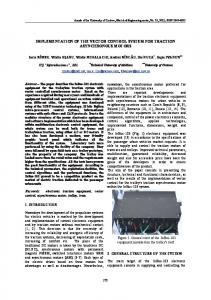
Fig. 4. A Sample Target Specification of Circuit in STG [8]
In the STG shown in Fig. 4, there are two output signals, called Ao and Ro, and two input signals, called Ai and Ri. The rising transition of Ao, labelled as Ao+, is followed by the transition Ri- . Also, the falling transition of Ao, labelled as Ao-, is followed by the transition Ri+. By using our guideline, the Promela code constructed from the STG in Fig. 4 is shown in Fig. 5. Two active proctypes are created for the two output signals, called MonitorAo() and MonitorRo(). Within each proctype, the do loop is created and the input signals next to the output transitions are fired as shown in the If-statements. The printf statement would capture the actual signal values of inputs and outputs at the ISBN: 978-988-19253-9-8 ISSN: 2078-0958 (Print); ISSN: 2078-0966 (Online)
Fig. 6. A Sample of the Circuit Implementation [9]
The asynchronous circuit implementation is drawn in the form of gate level diagram, which includes AND, OR, NOT, NOR, NAND, C-element, etc. Fig. 6 shows a sample of the circuit implementation of the STG shown in Fig. 4. The diagram would be converted into Promela code. The guideline describing how to construct the Promela code is shown as follows. 1) Create an active proctype in Promela for each element or gate G in the diagram IMECS 2015
Proceedings of the International MultiConference of Engineers and Computer Scientists 2015 Vol II, IMECS 2015, March 18 - 20, 2015, Hong Kong
2) Within the active proctype in (1) Loop forever to do Change the output signals according to the truth table of the type of the element or gate. Endloop
inputs and outputs observed at a particular moment. For example, s1 = and s2= are the two snapshots of the signals Ri, Ro, Ai, Ao of the Fig. 4 and Fig. 5. The SS = . Practically, the number of snapshots should be huge when the exhaustive checking is conducted. The SS is expected to demonstrate the snapshots of the formal model and this sequence is our key ingredient in our signal persistence checking scheme at last. D. Generate Signal Transition Sequences The Signal Transition Sequence (STS) is introduced to represent all of the possible unfolding sequences of signal transitions of each simple cycle in live STG. The STS is formally defined as a set = { L } where L is the sequence of transitions. A sequence of transitions is ntuple L = , where ti is either rising transition r+ or falling transition r-, and r is the signal name. For example, a STS = { , }. The STS includes all nodes of the STG, called transitions, and they are enabled/fired eventually. Therefore, the STS is used to test the liveness of the circuit implementation. The guideline of the extracting of the STS from the given STG (2 fan-in/2 fan-out) is shown in Fig. 8. Input A valid and live STG called G= where T is a set of transitions t and M is a set of marking M i where Mi is a ordered pair (t1,t2) and (t1,t2) F. t1 is called "before transition to M i" and t2 is called "next transition to Mi"
Fig. 7. The Promela Code of the Circuit Implementation
In the Fig. 6, two C-elements are drawn. The output signals, Ao and Ro are fed loopback as the inputs to each other C-element. By using the guideline, Two active proctypes are created, called Celement1() and Celement2(). The proctype simply perform the changing of the outputs according to the C-element’s truth table. Fig. 7 shows the Promela code of the circuit implementation of the diagram in Fig. 6. The printf statement also captures and provides us the Simulation Sequence (SS) during the simulation in SPIN. C. Generate Simulation Sequence We consolidate the Promela code from both the transition driver part (in Fig. 5) and the circuit implementation part (in Fig. 7) to construct our formal verification model. Then, the SPIN is used to simulate the behaviors of this system model. The printf statements are used as our instrument probing and generate the sequence of signal values, called Simulation Sequence (SS). The SS is formally defined as a n-tuple = where si is a snapshot of the observable signal values, and n is the number of snapshot where 1 i n. A snapshot is a k-tuple s = where vi is the ordered signal value (0,1) of the k numbers of ISBN: 978-988-19253-9-8 ISSN: 2078-0958 (Print); ISSN: 2078-0966 (Online)
Output A sequence STS called S={ L } where L is a sequence of transitions . For each marking Mi Create a null sequence L Loop until the marking Mi traverses back the start edge/position again Locate marking Mi = (ti,tj) If tj has more than one fan-in transitions then Append Extra of the other trigger transitions x's of tj to the sequence L EndIf Append tj to the sequence L Fire the transition tj so that the marking Mi move forward the unvisited edge Endloop Add sequence L to the set S For each sequence L in the set S For each Extra trigger transition xi Create a new sequence Lx similar to L In Lx, Swap order of the Extra trigger transition xi and the previous one Add sequence Lx to the set S EndFor EndFor Remark: The STS S is the union all of the sequence L and Lx so that the duplicate sequences are eliminated. Fig. 8. The Guideline to Extract the STS
We develop a tool to extract the STS using C# and the sample of the tool is shown in Fig. 9. In the tool, the rising and falling transitions are labelled as Ai1 and Ai0 instead of Ai+ and Ai-. IMECS 2015
Proceedings of the International MultiConference of Engineers and Computer Scientists 2015 Vol II, IMECS 2015, March 18 - 20, 2015, Hong Kong
Fig. 9. A Sample of the Signal Transition Sequence
E. Generate Signal Transition Sequences The Lock Relation Sequences (LRS) is introduced based on the definition of Lock Relation in [2]. Similar to STS, the LRS is formally defined as a set = { R } where R is the sequence of transitions. A sequence of transitions is k-tuple R = , where ti is either rising transition r+ or falling transition r-, and r is the signal name. However, each sequence of transitions R is based on Semi-Lock and FullLock Relation definition in [2]. For example, a LRS = { , < Ao-, Ro-, Ao+, Ro+>}. Therefore, the LRS is used to test the signal persistence of the circuit implementation according to [Park]. In our approach, only semi-lock and full-lock relation patterns are considered. In Fig. 10. The rising and falling transitions are labelled as Ai1 and Ai0 instead of Ai+ and Ai-.
within the transition position 593 to 608, etc. While, the second table, in Fig. 11, shows the coverage of LRS in the SS. The semi-lock sequence: Ao0 > Ro0 > Ao1, is found during the simulation step 6-10. The semi-lock sequence: Ri0 > Ao0 > Ri1, is also found during the simulation step 5-9, etc. While the full-lock sequence: Ao0 > Ro0 > Ao1 > Ro1, is found at the step 6-11, etc. The result in Fig. 12 concludes the number of STS and LRS found in the simulation sequence SS.
Fig. 10. A Sample of the Lock Relation Sequences
F. 2-Phase Signal Persistence Checking We propose a 2-phase signal persistence checking scheme to ensure the liveness and persistence of the circuit implementation written by gate level diagram. Firstly, the STS coverage checking is performed. As mentioned earlier, the STS represents all unfolding sequences of the transitions of the STG. If the SS, which represents the execution of the formal model, covers the STS, then the circuit implementation is also live. Every node of STG is reachable and fired eventually by the circuit implementation simulation found in the SS. Secondly, the LRS coverage checking is performed. If the circuit implementation, simulated by the SS, matches the patterns of the LRS, then it is also persistent. In order to support this signal checking approach, we develop a tool to perform this 2-phase signal persistence checking using C#. The STS coverage checking and the LRS coverage checking are performed shown in Fig. 11. The result is shown in Fig. 12. In Fig. 11, the first table shows the patterns matching of STS found in the SS. The transaction sequence SS splits into a set of subsequences of SS and the coverage testing is conducted by searching the sequences of STS in these subsequences of SS. In the sample table, STS3 is found firstly at the transition position 1 to 8. Then, STS5 is found ISBN: 978-988-19253-9-8 ISSN: 2078-0958 (Print); ISSN: 2078-0966 (Online)
Fig. 11. The STS Coverage and the LRS Coverage Checking
Fig. 12. Summary Result table
IV. CONCLUSION In this paper, we propose an alternative scheme of signal persistence checking of asynchronous system implementation. The circuit implementation drawn in gate level diagram is checking against its behavioral specification in STG. We also propose the 2-phase signal persistence checking using STS coverage and LRS coverage testing. We introduce how to generate STS and LRS and develop a software tool to support our approach. However, we focus only the STG with live, single cycle, and no freechoice. Our future works would concern more on the nonterminal signals and the delay of the circuit gate and its wiring.
IMECS 2015
Proceedings of the International MultiConference of Engineers and Computer Scientists 2015 Vol II, IMECS 2015, March 18 - 20, 2015, Hong Kong
REFERENCES [1]
[2]
[3]
[4] [5] [6] [7]
[8]
[9]
Dill L.D. and Clarke E. Automatic verification of asynchronous circuits using temporal logic. In Proceedings of the 1985 Chapel Hill Conference on VLSI, Computer Science Press, May 1985. Park,S.B, “Synthesis of Asynchronous VLSI Circuits from Signal Transition Graph Specifications. Doctoral dissertation, Department of Engineering-Computer Science, Tokyo Institute of Technology,1996. Tam-Anh Chu, “Synthesis of self-timed VLSI circuits from graphtheoretic specifications”, PhD thesis, Massachusetts Institute of Technology, June 1987. Hauck S. Asynchronous Design Methodologies: An Overview. Proceedings of the IEEE 1995, pp. 69-93. Christel Baier and Joost-Pieter Katoen, “Principles of Model Checking”, The MIT Press Cambridge, Massachusetts London, England, 2008 Gerard J. Holzmann, “Principles of the Spin Model Checker”, SpringerVerlag London Limited, 2008. Ke Jiang, “Model Checking C Programs by Translating C to Promela”, Institutionen för informationsteknologi, Department of Information Technology. September 2009. E.M.Sentovich, L.Lavagno et.al., “SIS: A system for sequential circuit synthesis”, Electronics Research Lab. Memorandum No. UCB/ERL M92/41, UC at Berkeley May 1992. Arthit Thongtak, "A Study on testing methodologies of asynchronous logic circuits," PhD Thesis, Dept. of Electrical and Electronics Engineering, Tokyo Institute of Technology, Japan, Jan.1996. (In Japanese).
ISBN: 978-988-19253-9-8 ISSN: 2078-0958 (Print); ISSN: 2078-0966 (Online)
IMECS 2015