tion Graph to be implemented by an asynchronous cir- ..... De nition 3.4 A state graph is said to satisfy the .... Given these characteristic functions, the transition.
Checking Signal Transition Graph Implementability by Symbolic BDD Traversal Alex Kondratyev Jordi Cortadella� Michael Kishinevskyy The University of Aizu Universitat Polit�ecnica de Catalunya The University of Aizu Aizu-Wakamatsu, 965 Japan 08071 - Barcelona, Spain Aizu-Wakamatsu, 965 Japan Enric Pastor� Oriol Roig� Alex Yakovlev z Universitat Polit�ecnica de Catalunya Universitat Polit�ecnica de Catalunya University of Newcastle upon 08071 - Barcelona, Spain 08071 - Barcelona, Spain Tyne, NE1 7RU England
Abstract This paper de nes conditions for a Signal Transition Graph to be implemented by an asynchronous circuit. A hierarchy of the implementability classes is presented. Our main concern is the implementability of the speci cation under the restricted input-output interface between the design and the environment, i.e., when no additional interface signals are allowed to be added to the design. We develop algorithms and present experimental results of using BDD-traversal for checking STG implementability. These results demonstrate e�ciency of the symbolic approach and show a way of improving existing tools for STG-based asynchronous circuit design.
This paper tackles both these problems. First, we de ne STG implementability classes and the properties that must be checked in order to ensure that a speed-independent circuit is derivable from the STG (Sections 2 and 3). Secondly, we develop algorithms and present experimental results of using BDDtraversal approach for STG implementability veri cation (Sections 4 to 6). These results demonstrate e�ciency of the symbolic approach.
2 STG implementability
Synthesis frameworks for asynchronous circuits based on STGs (see, e.g., [2, 6]) involve methods for STG analysis and veri cation. The main problem here is to check if a given STG is implementable by an asynchronous circuit. Although the existing literature de nes such conditions (namely, Consistency and Complete State Coding [2, 6, 10]), they do not re ect requirements to the interface between the circuit and its environment . Another shortcoming of the existing analysis methods is that they are based on explicit representation of the State Graph.Recent developements in using symbolic techniques for reachable state space traversal, based on Binary Decision Diagrams(BDDs) [1, 9], can be applied to avoid state space explosion.
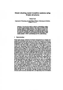
Let N = hP; T; F; m0 i be a Petri net (PN) [7], where P is the set of places, T is the set of transitions, F � (P � T ) [ (T � P ) is the ow relation, and m0 is the initial marking. A transition t 2 T is enabled at marking m1 if all its input places are marked. An enabled transition t may re, producing a new marking m2 with one less token in each input place and one more token in each output place (m1 ! m2 ). The sets of input and output places of transition t are denoted by �t and t�. Similar, �p and p� stand for the sets of input and output transitions of place p. The set of all markings reachable in N from the initial marking m0 is called Reachability Set. Its graphical representation is called Reachability Graph. An example of PN is shown in Figure 1,a. Signal Transition Graphs (STGs) are PNs whose transitions are interpreted as signal transitions. A signal transition can be represented by aj + (or aj ?) for the j-th transition of signal a from 0 to 1 (or from 1 to 0), while aj � is a generic name for either a rising or falling transition of a.
� This work has been partially supported by CICYT TIC 911036, Dept. d'Ensenyament de la Generalitat de Catalunya and ACiD-WG (Esprit 7225). y This work has been partly supported by The Danish Technical Research Council and by the U.K. SERC GR/J52327. z This work has been partly supported by the U.K. SERC GR/J52327.
De nition 2.1 [2] An STG D is a triple hN; SA ; �i, where N is a PN, SA is the set of signals that is a union of three non-intersecting subsets: SI ; SO and SH of input, output and internal (hidden) signals respectively, and � : T ! SA �f1; 2; . . . g�f+; ?g is the labelling function.
1 Introduction
p5
p1 t1 p2 t2
p0
p3 t3 p4 t4 (a)
p0
t5 p6
r1+
r2+
t6 p7 t7 p8 t8
a1+
a2+
r1-
r2-
a1-
a2(b)
Figure 1: A two-user mutual exclusion element. An STG example, which is the interpretation of PN from Figure 1,a, is shown in Figure 1,b. STGs are often shown in their shorthand form, where transitions are denoted by their labels (instead of bars) and places with only one input and output transition are omitted. The behavior of an STG and a circuit can be compared on the basis of the languages they realize. De nition 2.2 (Strong Equivalence) Circuit C with a set of signals A is strongly equivalent to STG D if: (1) there is one-to-one correspondence between signals A of C and SA of D, and (2) for each trace of signal transitions in C there is an equivalent trace of transitions in D and vice versa. If we somehow manage to check that the STG can have a strongly equivalent circuit, then the logic equations for all gates of the circuit can be derived by the STG in a conventional way [2, 3, 10]. This is why the STG that has a strongly equivalent implementation will be called gate implementable . If there is no circuit that is strongly equivalent to the STG speci cation, it might be that an equivalent circuit can be derived with some additional signals. De nition 2.3 (Projection) For a trace q over the set of signals SA the projection of q on the set of signals SB ; SB � SA , is a sequence q # SB which is obtained from q by deleting all transitions whose signals are not in SB . A projection of a set of traces of D (L(D)) on the set of signals SB is the set of projections of all traces from L(D) on SB (denoted by L(D) # SB ). De nition 2.4 (Trace equivalence) Two STGs D1 and D2 with signal sets SA1 and SA2 are trace equivalent by the set of signals SB , SB � SA1 \ SA2 , if L(D1) # SB � L(D2) # SB . Both STG and circuit behavior can be characterized by their trace sets. Thus, one can compare in this way two di�erent STGs, or two circuits, or an STG and a circuit.
De nition 2.4 restricts the behavior of observable signals (set SB ); no change in their ordering is allowed. For speci cations (circuits) with external inputs and outputs an equivalence that preserves the input-output (I/O) interface is needed. De nition 2.5 (I/O equivalence) Two STGs D1 and D2 with sets of signals SA1 and SA2 are I/O equivalent by the set of signals SB , SB � SA1 \ SA2 , if (1) they are trace equivalent by SB and (2) for the input and output signals of D1 and D2: SI 1 = SI 2 � SB and SO1 = SO2 � SB . Trace equivalence and I/O equivalence address different design tasks and conditions. If the task is to implement a module, then typically the I/O interface is xed for the module and it is necessary to use the I/O equivalence between the implementation and the original speci cation. However, it is often up to the designer to decide how to decompose the module into smaller blocks and what kind of interface to choose for these blocks. For the module decomposition, only trace equivalence may need to be ensured. In this paper we are primarily interested in the conditions of implementability when it is not allowed to change the interface. We have therefore distinguished the following (in the descending order of hierarchy) levels in the STG implementability: De nition 2.6 An STG D is called: (1) SIimplementable if there is a logic circuit C trace equivalent to D; (2) Input/Output SI-implementable (we will simply denote it I/O-implementable) if there is a logic circuit C I/O equivalent to D; (3) Gateimplementable if there is a logic circuit C strongly equivalent to D.
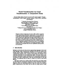
3 Properties of STGs Our check of STG implementability will be based on the BDD-based symbolic traversal of the reachable set of states [1, 9]. This helps to avoid or to mitigate state explosion. SG is a directed graph whose vertices correspond to the markings of the Reachability Graph. An SG vertex is labeled with a boolean vector s = hs1 ; . . . ; sn i, representing the value of the STG signals (n is the number of signals in the STG). This vector is called a state. Two states s1 and s2 corresponding to markings m1 and m2 are connected with an edge in the SG if m2 is reachable from m1 by the ring of some event a� of the STG (s1 a!i � s2 ). This transition ai � is called enabled in state s1 . Signal a is called enabled in state s if some transition ai � is enabled in s, otherwise a is called stable or disabled. In general, several states in the SG may correspond to one marking. Therefore, rst the full state
{p0,p1,p5} t1 t5 {p0,p2,p5} {p0,p1,p6} t5 t1 t6 {p0,p2,p6} {p1,p7} (a)
r1+
{0000}
r2+
{1000} {0010} r1+ a2+ r2+ {1010} {0011} (b) State:
{p0,p1,p5},{0000} t1 t5 {p0,p2,p5},{1000} {p0,p1,p6},{0010} t1 t6 t5 {p0,p2,p6},{1010} {p1,p7},{0011} (c)
Figure 2: State models graph [11] is build. Each vertex in such a graph is labelled by a pair (marking, state). The SG is then obtained by retaining only the state component in each vertex label. Figure 2,a-c illustrates the three types of state models: the reachability graph, the state graph and the full state graph for the mutual exclusion element.
3.1 Boundedness and consistency The behavior of the circuit must be nite . This is guaranteed by boundedness of the underlying Petri net. A PN (STG) is called k-bounded if for every reachable marking the number of tokens in any place is not greater than k. A PN (STG) is called bounded if there is such a nite k for which it is k-bounded, and if k = 1, then the PN (STG) is called safe . The STG shown in Figure 1,b is safe. Not every STG can be associated with a process of switching the circuit gates. Let us assume, for example, that the following sequence is feasible in an STG: b1 +; a+; b2 +; . . .. After ring b1 + signal b must be at logical 1, and no correct interpretation can be suggested to the following transition b2 +. Such incorrectness can be formalized in the SG terms by state assignment consistency . De nition 3.1 An SG has a consistent state assignment (we call such an SG consistent) i� for each pair of states s1 and s2 connected with the edge (s1 ! s2 ) the following conditions are met: (1) if the edge is labeled by a+ transition, then signal a is equal to 0 in s1 and to 1 in s2 ; (2) if the edge is labeled by a? transition, then signal a is equal to 1 in s1 and to 0 in s2 ; (3) in all other cases the value of signal a in s1 and s2 is the same. An STG D is SI-implementable only if it is bounded and its SG is consistent[2, 5]. The speci c feature of speed-independent implementation is captured by persistency .
3.2 Persistency Persistency means that if a circuit signal is enabled it has to re independently from the ring of other signals . However, one should distinguish between input and non-input signals. For inputs, which are controlled by the environment, it is possible to have a non-deterministic choice, which is represented in STG and SG models by con icts, i.e., disabling of one input signal by another input signal. Such con icts are always interpreted as choice and therefore do not lead to hazardous behavior. For non-input signals, which are produced by circuit gates, signal transition disabling may lead to a hazardous spike at the output of the gate, making the circuit behavior dependent on the gate delays. In the case phrased as \input is disabled by the output", we assume that these two signals are controlled independently, one by the environment and the other by the circuit. If the environment is ready to change the input while the circuit is ready to change the output of a gate, then these two processes, under a speed-independent interaction, cannot in uence each other. Therefore this is also a potential source of hazards and delay-dependence. De nition 3.2 SG G is persistent if: (1) any noninput signal cannot be disabled by another signal1 and (2) any input signal cannot be disabled by a non-input signal. The following proposition (similar to the one proved in [4]) shows that persistency is a necessary condition for the SI-implementability of STGs. Proposition 3.1 An STG is I/O-implementable only if the corresponding SG is persistent. Let us re ne the potential sources of persistency violation. De nition 3.3 (1) Transition ti is non-persistent in a PN N if ti enabled in some reachable marking m becomes disabled after the ring of another transition tj enabled in m. Non-persistency of ti with respect to tj is also called a direct con ict between ti and tj . (2) Signal a is non-persistent in an STG D if a is enabled in some reachable state s of the corresponding SG and it becomes disabled after the ring of another signal b also enabled in s. Signal persistency and transition persistency are closely related. Clearly, the only source of nonpersistency of a signal a is the non-persistency of some transition labelled with ai �. Yet not any nonpersistency of ai � leads to the violation of persistency by signal a. In Figure 3,a transitions labelled with a1 + 1 To deal with non-deterministic circuits (like arbiters) we can soften the requirement and allow the disabling of non-input signals in arbitration points.
and b2 + are both non-persistent. However, signals a and b are persistent in the corresponding SG in Figure 3,c. Although the ring of, e.g., a1 + disables b2 + it also enables transition b1 +. So, both before and after the ring of a1 +, signal b remains enabled. By the trace equivalence (De nition 2.4) such a behavior of signals a and b is equivalent to the concurrent ring of a+ and b+[6]. Therefore, both STG D1 and D2 have the same SG (Figure 3,c). One can conclude that for signal b the con ict of the transition b2 + is "fake". Fake con icts are discussed further in Section 3.5. p1
D1:
abc 0*0*0
D2:
a 1+
b+
b 1+
a 2+
a+
b+
2
p2
.. .
b+
10*0 c+
.. .
(b)
c+
a+
0*10 b+
a+
110* c+
.. .
(c)
(a)
Figure 3: Transition and signal non-persistency
3.3 Complete state coding SG descriptions are convenient for the derivation of the logic functions of signals. Unfortunately, this procedure is not always immediately possible even for nite, consistent and persistent SGs. The problem is with the state encoding, which may sometimes de ne the on- and o�-sets of the logic functions [2, 3, 6] not uniquely. De nition 3.4 A state graph is said to satisfy the Complete State Coding requirement if and only if (1) each state has a unique binary code, or (2) for pairs of states that have identical binary codes, the set of enabled non-input signals is identical. The CSC requirement is the necessary condition for the gate implementabilty. It is also the su�cient condition for the implementation on complex gates[2]. Given an STG speci cation that does not obey the CSC requirement, the following question arises: Is it possible to equivalently transform this speci cation to another STG for which the CSC requirement is met and therefore it is gate implementable? For the SIimplementability when it is allowed to change the interface of the design the answer to the question is positive, and any of the known methods can be employed to insert additional signals into the STG [3, 10, 6]. However, for I/O-implementability with the xed interface of the design CSC-violations can be classi ed into reducible and irreducible . Reducible CSCviolations can be solved by adding new non-input signals, irreducible violations require changes in the interface between the circuit and the environment.
3.4 CSC reducibility With every sequence q feasible in SG we will associate the unbalanced set of q that contains all the signals for which the numbers of their + and ? transitions in q are not equal. De nition 3.5 (1) An SG is called deterministic with respect to signal transition a� if for any state a� s1. s there is at most one state s1 such that s ! The SG is deterministic if it is deterministic for all signal transitions. (2) An SG is called commutative with respect to signal transitions a� and b� if for any a� s1 ! b� s3 and states s; s1; s2; s3; s4 such that s ! b � a � s ! s2 ! s4, s3 is equal to s4. The SG is commutative if it is commutative for all pairs of signal transitions. (3) An SG has mutually complementary input sequences if there is a state s which gives rise to two distinct nite sequences of input transitions which have the same unbalanced sets and which lead to two di�erent states. It might be shown that a consistent and persistent SG of a bounded STG is CSC-reducible if it is deterministic, commutative and free from mutually complementary input sequences. The following proposition shows the list of properties necessary and su�cient for the I/O-implementability of STGs. Proposition 3.2 An STG is I/O-implementable i� it is bounded and its SG is consistent, persistent and CSC-reducible. Obviously, if an STG has a SG that obeys CSC requirement, then the STG is gate-implementable.
3.5 Fake con icts In this section we demonstrate another property of STG, of a well-formedness type, which can be helpful in two ways. Firstly, it will provide a useful mechanism for performing e�cient veri cation of commutativity and persistency within the BDD-framework, where the SG is not available in its explicit form. Secondly, it can assist the designer in optimising the initial STG description. De nition 3.6 (Fake con ict) [5] A direct con ict between two signal transitions ai � and bj � is called
fake if the ring of one of them does not disable the signal of the other. Figure 4 shows two types of fake con icts: asymmetric and symmetric. Obviously, if the STG has a commutative SG, then each symmetric fake con ict must correspond to the commutative subgraphs of the STG and the SG, and can therefore be always transformed to the equivalent parallel subgraphs of the
m *a i
m *a i
*b j
m1
m2
*b k
*a r m3
m4 a)
*b j
m1
m2
m3
m4
*b k
*a r
b)
Figure 4: Fake con icts STG and SG as exempli ed in Figure 3. Asymmetric fake con icts involving at least one non-input signal always contradict one of the persistency conditions in De nition 3.2 and therefore lead to the violations of SI-implementability. Asymmetric fake con icts between two input signals are not dangerous, since they are interpreted as a choice between two alternative traces. An STG is called fake-free STG if there are no symmetric fake con icts and there are no asymmetric fake con icts involving a non-input signal. The following properties [5] illustrate use of fake con icts: (1) If an STG has the persistent and commutative SG, then it can always be transformed to the equivalent fake-free STG. (2) A fake-free STG is commutative. (3) A fakefree STG has a persistent SG i� all transitions labelled with non-input signals are persistent. Therefore, one can either exclude fake con icts by an equivalent transformation of the STG or the STG (and its SG) is not persistent and hence not I/Oimplementable. Therefore, in the analysis of implementability we always reject STG speci cations with symmetric fake con icts and non-input asymmetric fake con icts. Fake con icts can be analyzed by the structure of the STG and that is much simpler than the check for commutativity.
4 Modeling Petri nets and STGs with logic functions Given an n-variable logic function f : B n ! B , the functions fxi = f (x1 ; . . . ; xi?1 ; 1; xi+1 ; . . . ; xn ) and fx0i = f (x1 ; . . . ; xi?1 ; 0; xi+1 ; . . . ; xn ) are called the positive and negative cofactors of f with respect to xi . The de nition of cofactor can be extended to cubes (sets of literals). The existential abstraction of f with respect to xi is de ned as: 9xi f = fxi + fx0i . Let N = hP; T; F; m0 i be a safe Petri net and MP the set of all markings of N (n = jP j; jMP j = 2n ). A marking can be represented by a boolean vector m = (p1 ; . . . ; pn ), where pi = 1 (pi = 0) denotes that pi is marked (not marked) 2 . Each set of 2 Unsafe -bounded places can be represented by several boolean variables [9]. k
markings M 2 2MP has a characteristic logic function �M : B n ! B , that equals 1 for those vertices that correspond to markings in M . For example, given the Petri net depicted in Figure 1,a , the characteristic function of the set of markings M = f(0,1,0,0,1,0,0,0,0), (0,1,1,0,1,0,0,0,0), (1,1,0,0,1,0,0,0,0), (1,1,1,0,1,0,0,0,0), (1,1,1,1,1,0,0,0,0) g is calculated as the disjunction of boolean vectors m 2 M . The resulting function is �M = p1 p4 p05 p06 p07 p08 (p0 p2 + p03 ). The transition function of a Petri net is a function �N : 2MP � T ?! 2MP ; that transforms, for each transition, a set of markings M1 into a new set of markings M2 as follows: M2 = �N (M1 ; t) = fm2 2 MP : 9m1 2 M1 ; m1 !t m2 g. Computation of the transition function can be e�ciently implemented by using the topological information of the PN. Let us present the characteristic function of some important sets related to a transition t 2 T : ^ E(t) = pi ( enabled), ASM(t) = NPM(t) = NSM(t) =
pi^ 2� t
pi^ 2t� pi^ 2� t pi 2t�
t
pi (all successors marked), p0i (no predecessor marked), p0i (no successor marked).
Given these characteristic functions, the transition function can be computed as follows: �N (M; t) = (ME(t) � NPM(t))NSM(t) � ASM(t): Assume that in the example of Figure 1,we calculate M1 = �N (M; t1 ) given the set M = p0 p1 p02 (p5 p06 + p05 p6 ) + p01 p3 p5 p06 p07 : First, ME(t1 ) (cofactor of M with respect to E(t1 ) = p1 ) selects those markings in which t1 is enabled and removes its predecessor places from the characteristic function (ME(t1 ) = p0 p02 (p5 p06 +p05 p6 )). Then the product with NPM(t1 ) = p01 eliminates the tokens from the predecessor places (ME(t1 ) � NPM(t1 ) = p0 p01 p02 (p5 p06 + p05 p6 )). Next, the cofactor with respect to NSM(t1 ) = p02 removes all the successor places, obtaining (ME(t1 ) � NPM(t1 ))NSM(t1 ) = p0 p01 (p5 p06 + p05 p6 ). Finally, the product with ASM(t1 ) = p2 adds a token in all the successor places of t1 (M1 = p0 p01 p2 (p5 p06 + p05 p6 )). Let D = hN; SA ; �i be an STG with N as underlying Petri net. Let G be the SG corresponding to the STG D, and C the set of labels (state codes) of the states of G. Since there is a correspondence between markings of N and states of G, we represent the full state of the STG by the vector y = (m; s), where m is a marking of N and s the state code of the corresponding state in G, respectively. The transition function can now be extended for STGs as a function �D : 2(MP �C ) � T ?! 2(MP �C ) .
For a set of full states MF , �D is de ned as follows: � if �(t) = ai + F ; t))a0 � a �D (MF ; t) = ((��NN ((M MF ; t))a � a0 if �(t) = ai ?
5 Veri cation of implementability conditions STG implementability properties can be veri ed by calculating all reachable markings (states) of the STG. Given the initial marking m0 of N and the initial values of the signals s0 , the set of states of an STG can be calculated by using symbolic traversal techniques, similar to those used for the veri cation of nite state machines. Figure 5 describes an algorithm for symbolic traversal. It starts from an initial full state (m0 ; s0 ). For each outermost iteration, all transitions of the Petri net are visited and red from all the new states found so far. The algorithm halts when a xed point is reached (no new states are generated). traverse STG (D) f Reached = From = f(m0 ; s0 )g; repeat for each
t 2 T do To = �D ( From; t); From = From [ To;
endfor
New = From ? Reached; Reached = Reached [ New; From = New; until ( New = ;); return Reached; /* The set of reachable states of D */
g
Figure 5: Algorithm for symbolic traversal of an STG
5.1 Boundedness and consistency The check that an STG (PN) is k-bounded or safe can be done within the BDD-framework by means of the technique described in [9]. Verifying that the STG is consistent can be done during the traversal, by checking the consistency of the new generated states. We rst de ne the following characteristic function: _ E(a�) = E (t) (a� is enabled) t:�(t)=a�
The characteristic function of the states with inconsistent assignment is derived according to De nition 3.1: Inconsistent(a+) = E (a+) � a(a + enabled and a = 1)
Inconsistent(a?) = E (a?) � a0 (a ? enabled and a = 0) Inconsistent(a) = Inconsistent(a+) + Inconsistent(a?) Inconsistent(D) =
_ a2SA
Inconsistent(a)
Let us call R(D) the set of reachable states (markings and binary codes) of the STG D. D is inconsistent if R(D)\ Inconsistent(D) 6= ;. An additional problem may appear in case the state assignment of the initial marking is unknown. A simple solution for that is to initially assign a \don't care" value for all signals (or equivalently, to not encode signals in the initial marking). As soon as a marking with some ai + enabled is generated, all reachable markings obtained so far are encoded with a = 0 (similarly for ai ?).
5.2 Persistency A transition can only be non-persistent if some of its input places is a con ict place (more than one predecessor). For some classes of Petri nets persistency is guaranteed by the structure of the net, e.g. marked graphs are always persistent since all places have only one successor transition [7]. An algorithm to check transition persistency is shown in Figure 6(a). Only pairs (ti ; tj ) of transitions with some common predecessor place are analyzed. Let R(N ) be the set of reachable markings of N . The set of markings with ti enabled are calculated. Next, the set of markings reachable in one step by ring some transition tj 6= ti are obtained. If ti is not enabled in any of those markings, then ti is not persistent. A similar algorithm to check the signal persistency is given in Fig. 6(b).
5.3 Complete State Coding The CSC requirement can be checked for each noninput signal by de ning the following characteristic functions: ER(a+) = 9P (R(D) � E (a+)) ER(a?) = 9P (R(D) � E (a?)) QR(a+) = 9P (R(D) � a ? E (a?)) ? � QR(a?) = 9P R(D) � a0 ? E (a+) ER(a�) is the set of binary codes that correspond to states in which some ai � is enabled (a set of excitation regions ). It is obtained by abstracting the places (9P ) from the states of the excitation region. QR(a+) (a set of quiescent regions) is the set of binary codes that correspond to states in which a = 1 but a? is not enabled (similarly for QR(a?)). The CSC requirement for non-input signal a can now be checked as follows [8]: CSC(a) = (ER(a+)\QR(a?) = ;)^(ER(a?)\QR(a+) = ;)
transition persistency �(N ) f for each p 2 P , jp j > 1 do � for each ti
2p
do
Enabled = R(N ) � E (ti );
g
for each tj 2 p� ; ti 6= tj do if (�N ( Enabled; tj ) \ E (ti )0 6= ;) error (\ti disabled by tj "); end for end for end for
(a) signal persistency (N )�f for each p 2 P , jp j > 1 do �
2 p do Enabled = R(N�) � E (ti ); for each tj 2 p ; ti 6= tj do /* Let �(ti ) = ai � and �(tj )0 = bj � */ if (�N ( Enabled; tj ) \ E (a�) 6= ;) error (\a� disabled by b�");
for each ti
g
end for end for end for
(b)
Figure 6: Algorithms to verify persistency
CSC(D) =
^ a2SO [SH
CSC(a)
The CSC-irreducibility check can draw upon the results of the above CSC analysis. To check the existence of mutually complementary input sequences, we can proceed for each non-input in the following way: Let CONT (a) be the set of contradictory states for noninput a, de ned by CONT (a) = (ER(a+) \ QR(a?)) [ (ER(a?) \ QR(a+)). We rst take all the states in (QR(a+)[QR(a?))\CONT (a), and then traverse the net backward with \frozen" non-inputs (i.e., ring only input signals) until the xed point is reached. Then the forward traversal with frozen non-input signals is performed from the set of states obtained by the backward traversal. As a result, the set ReachedFrozen is obtained. If ReachedFrozen \ (ER(a?) [ ER(a+)) \ CONT (a) 6= ;, then there is a CSC problem for a with a mutually complementary input sequences. The set of states violating nondeterminism for signal change a� is trivially de ned by: S ti ;tj 2T; �(ti )=�(tj )=a� E (ti ) \ E (tj ). Instead of the relatively complex commutativity check, which must be performed individually for each state with more than one enabled signal, we check the freedom from the fake con icts.
5.4 Fake con icts One can simplify the check of both SG commutativity (another case for CSC-irreducibility) and persistency by checking for fake-freedom and transition persistency. An outline of the procedure which determines if there is any fake con ict in an STG D (N is the underlying PN) with respect to a signal transition ti is as follows: We start with the set of reachable states in which ti is enabled: Enabled = R(N ) \ E (ti ).� Then for each tj ; tk 2 T such that 9p 2 P : ti ; tj 2 p ; ti 6= tj ; tk 6= ti ; tk 6= tj ; �(tk ) = �(ti ) = a�, we check if the set of states reached from Enabled by ring tj contains at least one such state that enables tk , which is labelled with a� as ti (formally, if �N (Enabled; tj ) \ E (tk ) 6= ;). If all these checks return false, the STG is fake-free with respect to ti . The check for symmetric and asymmetric fake con icts is a simple modi cation of this basic technique.
6 Experimental results Several examples have been used to evaluate the ef ciency of the proposed algorithms. Most examples are scalable, in such a way that the number of states of the system can be exponentially increased by iteratively repeating a basic pattern. Despite the regularity of these scalable examples, we have found that BDDs may have an exponential size if appropriate heuristics for variable ordering are not used. Table 1 shows the obtained results. CPU time for each algorithm is presented. First, STG traversal and consistent state assignment are executed simultaneously (T+C). Next, non-input persistence (NI-p) and commutativity (Com) are veri ed by using the set of reachable states. Finally, CSC is veri ed. Since the master-read and Muller's pipeline examples are marked graphs (no con ict places), the CPU time to check persistency and commutativity is negligible. The BDD sizes reported in Table 1 correspond to the size of the Reached set in the traversal algorithm. The number of variables of the BDD is the number of places plus the number of signals. The results show how STGs with a high degree of parallelism and an extremely vast state space can be veri ed in moderate CPU times.
7 Conclusion We have presented formal conditions for an STG to be implemented by a speed-independent circuit under three di�erent notions of behavioral equivalence. The most practical one is Input-Output implementability, which takes into account speci c requirements about the interface between the circuit and its environment. This is re ected in the notions of persistency and CSC-reducibility. Consistency is also de ned in a more general form than before { for a full state graph, thus covering the case when one marking of an STG may correspond to several di�erent states. We have developed and implemented algorithms for checking these properties using symbolic rather than tradi-
Example master-read dining philosophers n
-stage Muller's pipeline -user DME arbiter n
n
# of places 36 10 90 20 180 30 270 30 120 45 180 60 240 20 81 40 161 60 241 n
# of signals 13 30 60 90 30 45 60 40 80 120
# of states 8932 6 0 � 107 3 7 � 1015 2 2 � 1023 6 0 � 107 6 9 � 1011 8 4 � 1015 2 2 � 107 4 5 � 1013 7 0 � 1019 :
: :
:
: :
:
: :
BDD size peak nal 437 225 2134 913 8557 2019 28002 3381 7897 4784 23590 10634 53446 18788 1688 1688 6568 6568 14648 14648
CPU (seconds) T+C NI-p CSC Total 1 0 0 1 34 3 14 51 765 142 18 927 3296 551 45 3897 132 0 38 170 740 0 120 860 3210 0 315 3525 9 2 2 13 82 17 16 117 286 56 56 403
Table 1: Experimental results tional explicit state-enumeration techniques. Such an approach generates and explores the set of reachable states in the form of their boolean characteristic functions represented by BDDs. Experimental results show that this method greatly reduces time spent on STG veri cation, thus improving the overall performance of the STG-based synthesis process.
Acknowledgements We are grateful to Alexander Taubin for many useful discussions.
References [1] Randal Bryant. Symbolic boolean manipulation with ordered binary-decision diagrams. ACM Computing Surveys, 24(3):293{318, September 1992. [2] T.-A. Chu. Synthesis of Self-timed VLSI Circuits from Graph-theoretic Speci cations. PhD thesis, MIT, June 1987. [3] M. Kishinevsky, A. Kondratyev, A. Taubin, and V. Varshavsky. Concurrent Hardware: The Theory and Practice of Self-Timed Design. John Wiley and Sons, London, 1993. [4] M. Kishinevsky and J. Staunstrup. Checking speedindependence of high-level designs. In International Symposium on Advanced Research in Asynchronous Circuits and Systems, pages 44 { 53, Salt Lake City, Utah, USA, November 1994. [5] A. Kondratyev and A. Taubin. On veri cation of the speed-independent circuits by STG unfoldings. In International Symposium on Advanced Research in Asynchronous Circuits and Systems, pages 64 { 75, Salt Lake City, Utah, USA, November 1994. [6] L. Lavagno and A. Sangiovanni-Vincentelli. Algorithms for synthesis and testing of asynchronous circuits. Kluwer Academic Publishers, 1993. [7] T. Murata. Petri nets: Properties, analysis and applications. Proceedings of IEEE, 77(4):541{580, April 1989.
[8] E. Pastor and J. Cortadella. Polynomial algorithms for the synthesis of hazard-free circuits from signal transition graphs. In Proceedings of the International Conference on Computer-Aided Design, pages 250{ 254, November 1993. [9] E. Pastor, O. Roig, J. Cortadella, and R. Badia. Petri net analysis using boolean manipulation. In 15th International Conference on Application and Theory of Petri Nets, pages 416 { 435, Zaragoza, Spain, June 1994. [10] P. Vanbekbergen, F. Catthoor, G. Goossens, and H. De Man. Optimized synthesis of asynchronous control circuits from graph-theoretic speci cations. IEEE Transactions on Computer-Aided Design, pages 1426{ 1438, November 1992. [11] A. V. Yakovlev. Synthesis of hazard-free asynchronous circuits from generalised Signal-Transition Graphs. Technical Report Series 377, University of Newcastle upon Tyne, Computing Science, April 1992.