SIGNAL PROCESSING AT 250 MHZ USING HIGH-PERFORMANCE FPGA’s Brian Von Herzen Rapid Prototypes, Inc., 675 Fairview Dr. Suite 246, Carson City, NV 89701 1-800-227-2743, 1-800-278-7662 FAX,
[email protected]
ABSTRACT
2. CORRELATION SPECTROMETERS
This paper describes an application in high-performance signal processing using reconfigurable computing engines: a 250 MHz cross-correlator for radio astronomy. Experimental results indicate that CMOS FPGA’s can perform useful computation at 250 MHz. The notion of an “event horizon” for FPGA’s leads to clear design constraints for high-speed application developers, and can be applied to a variety of real-time signal processing algorithms. Recent estimates indicate that higher-performance FPGA’s available early in 1998 can attain speeds of over 300 MHz using 20% fewer logic elements than current designs.
Radio astronomers analyze spectra using high-performance realtime computers.3 High-frequency radio astronomy, particularly millimeter-wave and sub-millimeter astronomy, utilizes wideband spectrometers with at least 1-2 GHz of spectrometer bandwidth. Weak astronomical signals require full-parallel integration on all of the channels to detect measurable signals. Therefore scanning spectrometers do not work for this application. Acousto-optic spectrometers can achieve the broad bandwidth, but become problematic in large arrays and for space-borne applications where adjustments of the analog elements become very difficult.
The results of this design work provide important clues on how to improve FPGA architectures for signal processing at hundreds of MHz. Direct routing channels between logic elements can significantly increase performance. Routing architectures with four-way symmetry allow for rotations and reflections of subcircuits needed for optimal packing density. Experimental results indicate that clock buffering often limits the top speed of the FPGA. Wave pipelining of clock distribution network may improve FPGA performance. Keywords: FPGA, real-time signal processing, correlators, programmable logic, manual partitioning and placement, event horizon. 1. RECONFIGURABLE COMPUTERS Field-programmable gate arrays (FPGA’s) can provide a useful platform for high-performance computing and real-time interactive signal processing. 1 These arrays perform well on real-time computations because they provide the speed of dedicated circuitry while retaining the flexibility of a programmable system. Reconfiguring allows for incremental optimization and improvement of hardware much like software development techniques. Because each element in an FPGA performs a dedicated task, application developers can readily design each circuit in the system for a specified performance, ideal for real-time signal processing, which requires that data flow through the system at a specified rate. This paper will describe a real-time application in radio astronomy that makes use of the fastest FPGA’s available, and performs a computation at speeds heretofore only achievable in custom silicon.2 The reconfigurable computer retains the flexibility to implement different performance tradeoffs, allowing for large arrays of simple computations or short arrays of complex computations. Reconfiguring the computer on demand provides a unique flexibility that has not existed before.
Another alternative uses a parallel digital correlator that computes the auto-correlation function of the incoming baseband signal.2 A digitizer quantizes the signal at a resolution of one, two or three bits.4 A 1:16 time-division de-multiplexer reduces the data rate from a Nyquist sampling rate of 4 Gs/s down to 250 Ms/s, producing 16 parallel data streams of 250 Ms/s. The streams pass into an array of cross correlators that correlate every stream with every other 250 MHz stream. Digital integrators accumulate the cross-correlation results for periods of 106 to 1012 samples, and the integration results pass to a microprocessor for further integration. The processor reassembles the auto-correlation of the 2 GHz input signal from the array of cross-correlation results and computes the Fourier transform of the correlation, producing the spectrum of the 2 GHz signal. In this paper we will focus on the 250 MHz cross-correlation portion of the algorithm, the heart of the real-time computation. This building block serves as the basic element in a large array of spectrometers for the Caltech Submillimeter Observatory5 and the James Clerk Maxwell Telescopes on Mauna Kea, Hawaii.6
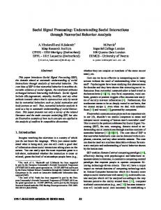
2.1 Cross-correlator architecture Figure 1 shows the basic architecture of a single crosscorrelator. Two 2-bit digital signals enter the correlator, called the prompt and delayed signal. Each lag of the correlator delays the delayed signal by one more clock than the prompt signal, hence the naming convention. A hardware multiplier at each lag computes the product of the prompt data and the delayed data, and offsets and rounds the result to 3 bits. An accumulator integrates the rounded products and passes its carry bit to a ripple counter acting as an accumulator. The ripple counter accumulates for integration times approaching 10 billion samples for astronomical applications, whereupon the results pass to a host computer, the counters reset, and the integration process repeats. This computation occurs at each lag in the correlator. The prompt and data signals emerge from the right side of the corre-
lator to permit daisy-chaining of the correlator chips to form longer correlators.
a predetermined number of cycles, after which the integration results go to a micro-controller for low-bandwidth processing.
Block Diagram of Correlator Architecture
Delayed Data (2 bits @ 250 Ms/s) -1 -1 Z Prompt Z Data 2x2 bit * * MPY
-1
-1
-1
-1
-1
-1 Delay Out
Z
Z
Z
Z
Z
Z Prompt
*
*
*
*
*
*
Out
+
+
+
+
+
+
+
+
A C Ripple C Counter U Accum. M
A C C U M
A C C U M
A C C U M
A C C U M
A C C U M
A C C U M
A C C U M
L A G
L A G
L A G
L A G
L A G
L A G
L A G
L A G
4-bit ACC
Slow output to host Micro.
Figure 1. Block diagram of a cross-correlator.
2.2 Design of an individual correlator lag Figure 2 shows the architecture of an individual correlator lag. Delayed and prompt data enter the lag on the west side and pass through registers on the rising edge of the clock. Combinational logic computes a three-bit rounded product using the values listed in Table 1. In the signed-magnitude number representation, the data values correspond as follows: (11) = -3, (10) = -1, (00) = +1, and (01) = +3. Normally this would produce products from -9 to +9. We offset these products by +9 and divide by 3 to get the range 0 to 6. Then we round the four central entries in the table to the value 3 to get integer values. The resulting entries appear in Table 1. Multi-3 -1 +1 +3 2x2 bit mpy plicand MultiSigned 11 10 00 01 plier Magn. -3 11 6 4 2 0 -1 10 4 3 3 2 +1 00 2 3 3 4 +3 01 0 2 4 6 Table 1: Modified and offset multiplication table for two-bit correlation input signals. The multiplier rounds and offsets the products to produce three product bits instead of four, allowing 3-bit unsigned addition further down the pipeline. This table produces 3-bit products that have LSB’s of the inner products rounded, with all the products offset to produce positive results. The offset allows the logic to have unsigned adders, accumulators, and up-counters. Later a micro-processor eliminates the offset by tracking the total number of samples and subtracting the number of samples times the fixed offset of 3 from the correlator results. The product goes to a 4-bit accumulator whose carry output controls a ripple counter for integration. The correlator runs for
Figure 2: Basic schematic of a single correlator lag. This basic algorithm repeats for each lag in the correlator array. The next two sections describe the optimizations to the architecture needed to obtain the performance objectives of 250 MHz real-time throughput with the correlator. 3. HIGH-SPEED FPGA’s FPGA technology frequently uses lookup tables based on static memory coupled with synchronizing registers. For this application, we used the XC3195-09 chip from Xilinx7. This architecture utilizes two 4-bit lookup tables and two flip-flop registers per configurable logic block (CLB). These chips provide ample resources for small-scale pipelining, the key to achieving high throughput in FPGA’s. Two approaches to high-speed FPGA design include top-down system design and bottom-up library element design. Here we use a bottom-up methodology where we set the target clock frequency in advance, and then design each element to meet the performance objectives from the start. These library elements connect using standard synchronous pipelining as long as the connections between elements remain short enough to stay within the synchronous timing window. We chose to design at 250 MHz based on rough performance estimates and the constraint that the clock frequency must divide 4-GHz sampling rate by a power of 2. In addition, we had completed a full-custom design at 250 MHz using 1.2 µm CMOS,2 and wanted to compare the performance of full-custom with FPGA technologies. From the 4.0 ns cycle time we must subtract 0.1 ns for clock skew on the FPGA, providing 3.9 ns to travel from register to register on the chip. Using worst-case timing tables for the 3195-09 device,8 it takes 1.3 ns to go from the rising edge of the
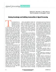
clock to the CLB output, with a setup time to the CLB of either 1.5 ns for lookup-table inputs or 1.0 ns for direct-in (DI) data inputs. Table 2 shows the overall timing budget. The X-Delay timing analyzer reports a maximum clock skew of 0.1 ns between internal CLB’s for the 3100-09. A design frequency of 250 MHz allows for 1.1 ns of allowable wiring delay for normal CLB inputs and 1.6 ns of wiring delay for DI inputs. The DI inputs do not pass through the lookup tables before going to the flip-flop registers. These wiring delays on the -09 series allow nearest neighbor communication using the direct data lines between CLB’s within 1.1 ns, and occasionally diagonal data propagation to normal data inputs. Figures 3 and 4 show the wiring delay from a central CLB to other nearby CLB’s. Direct interconnect takes 0.3 ns, and general routing resources take significantly longer. A 250 MHz system can use any routing channel of less than 1.1 ns for general inputs and any routing channel of less than 1.6 ns for direct data inputs (DI) to the CLB registers. These constraints determine the event horizon for a 250 MHz system, as shown in Figures 2a and 2b. Utilizing this design methodology, the entire chip can operate with worst-case cycle delays of under 4.0 ns. Future FPGA design tools could show for any selected CLB the event horizon for that CLB at a specified clock frequency, perhaps with the entire neighborhood highlighted in green. This could vividly show designers how far they could go with a signal before resynchronization. through via DI LUT pin Total cycle time 4.0 4.0 On-chip clock skew 0.1 0.1 Clock to output time 1.3 1.3 Setup time 1.5 1.0 Maximum wire delay 1.1 1.6 Table 2: Timing budget at 250 MHz from one synchronous register to another. The DI pin bypasses the lookup table (LUT), providing a longer maximum allowed wire delay.
The XC4000EX/XL regained direct interconnects, but only in the east and south directions, exacerbating the directionality problems of the original XC3100A architecture. Symmetry makes rotations and reflections of sub-circuits possible, an important operation for building larger systems. Hopefully future FPGA architectural designers will see the benefits of directional symmetry for routing networks in FPGA’s. .
Event Horizon at 250 MHz for DI Pin 2.4
2.4
1.9
1.4
1.4
1.9
2.2
1.7
1.3
0.3
0.9
1.3
1.3
1.8
0.0
0.3
1.0
1.3
1.7
1.7
0.3
1.7
1.2
0.3
0.6
0.8
1.2
1.8
1.9
1.6
1.1
1.1
1.7
2.0
2.5
Figure 3. The maximum distance a signal can travel in a single cycle using the DI input pin on the CLB. All data communications must lie within this event horizon to meet the timing specifications.
Timespec
Note that signals travel faster to the east than to the west, and slightly faster south than north. The standard orientation of the Xilinx device in the EditLCA editor defines east and west, north and south, i.e. pin 1 located in the northwest corner, facing the surface of the die. These directional biases in the 3100 family constrain the orientation of the chip relative to the desired data flow direction. When floorplanning a large chip, designers must often rotate and reflect a sub-circuit for optimal packing density. Directional biases reduce the maximal packing density and operating speed of FPGA’s, and may stem from a habit of drawing schematics from left to right, and translating these schematics into chip layouts fairly literally. Newer FPGA’s such as the XC4000 propagate signals at the same speed to the east and west, but the larger size of the XC4000 CLB reduces pipeline performance relative to the XC3100 in the same chip technology. The XC4000 family lost all direct interconnects, significantly increasing the time for nearest neighbor communications.
Event Horizon for LUT’s at 250 MHz 2.4
2.4
1.9
1.4
1.4
1.9
2.2
1.7
1.3
0.3
0.9
1.3
1.3
1.8
0.0
0.3
1.0
1.3
1.7
1.7
0.3
1.7
1.2
0.3
0.6
0.8
1.2
1.8
1.9
1.6
1.1
1.1
1.7
2.0
2.5
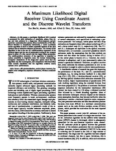
Figure 4. The maximum distance a signal can travel in a cycle passing through a single lookup table (LUT) before synchronization. The event horizon indicates the wire limits for a desired clock frequency. 3.1 Estimates for the XC4000XL device architecture Recently Xilinx has focused its high-speed efforts on the XC4000XL family. Worst-case timings for this family provide a performance comparison with the 3100A family. The XC4000XL CLB has more symmetry and has internal RAM capability, useful for high-density accumulators. Early estimates
indicate that a correlator lag may require 20% fewer CLB’s in the XC4000XL than in the XC3100A design. Xilinx produces the XC4000XL-1, the fastest speed grade currently available. For this speed grade, the timing budget includes 0.1 ns clock skew, 1.6 ns clock to out for the CLB, 1.2 ns of routing delay, and 0.9 ns to pass through the lookup table and setup the next register. This gives a total of 3.8 ns for the CLB delays. Assuming that the clock and I/O systems can keep up, worst-case CLB timing indicates operation at 263 MHz. Xilinx has indicated that the -09 speed grade available early in 1998 will increase the top speed of this family by 15%, suggesting maximum operating speeds of over 300 MHz in 1998. This speedup illustrates one of the important advantages of FPGA designs over ASIC designs: without any additional engineering work, the design gets faster as new FPGA speed grades become available. 4. ON-CHIP CORRELATOR ARCHITECTURE The schematic of Figure 2 would probably not operate at 250 MHz by itself. The methodology described in the previous section can transform this schematic into a highly pipelined design operating at 250 MHz. For a synchronous 250 MHz system, the global clock must register every CLB output. The inputs for any lookup tables must come from nearby CLB’s. Spanning distances of 3 CLB’s requires the DI pin. Each CLB has only one DI pin, which limits the maximum density of the design at times. The following subsection shows how to transform the schematic of Figure 2 into a re-timed architecture meeting all of these design methodology constraints.
4.1 Re-timing of the lag architecture The lag architecture of Figure 2 has a number of long propagation paths that benefit from pipelining for maximum-speed operation. Pipelining for a 250 MHz system requires breaking down each combinational circuit into 4-input lookup tables (LUT’s) immediately followed by a register. Any combinational blocks larger than 4 inputs must divide into two or more blocks with a new register in the middle so as to meet the single LUT rule between registers. Fortunately, some of the logic in the multiplier can combine with some logic in the 4-bit accumulator to shrink the total number of CLB’s. For example, the LSB of the multiplier can combine with the half adder to produce a running sum and carry bit for the LSB of the accumulator in a single CLB. Both sum and carry pass through a register. The carry propagates during the following cycle to the next bit of the accumulator. In this way the pipelined architecture processes one bit of carry per cycle in a pipelined fashion and need to only traverse one lookup table between registers. Two 4-input LUT’s in a single CLB can absorb all of the logic in the middle and MSB bits of the product. The sign and magnitude bits of the prompt and delayed data all affect these product bits. If all four input registers lie adjacent to a single CLB, then that single CLB can compute two bits of product in each cycle. Registers latch these two product bits and pass them to the accumulator for further processing. A bit-pipelined accumulator provides maximum performance for carry chains. By breaking the carry chain into single-bit stages, carries only traverse a single LUT between each register. Addi-
D ela yed S ign
D ela yed M ag .
P ro m pt S ig n
P ro m pt M ag .
Figure 5: Re-timed correlator lag circuit that has only one 4-input lookup table between registers. Each box with a large label represents a single CLB. Note the high packing density for the MID and MSB bits of the multiplier. They fit in a single CLB because only four inputs feed that circuit.
tional registers delay each input operands as needed to align the inputs. The LSB accumulator computes one result each cycle and passes it to the MID accumulator on the next cycle, which passes its result to the MSB accumulator on the following cycle. The re-timed schematic appears in Figure 5, including all of the data registers required to properly re-time the schematic.
taining a single-hop distance between lags. Placing the LSB logic to the northwest of the MID/MSB product permits nearestneighbor communication to all the product CLB’s, since the four data inputs can lie in any permutation around the cross. The wiring delay from the LSB product to the MID accumulator bit requires two pipeline stages. Two pipeline stages permit the LSB result to pass south by two rows, and the other input data has to pass through an equal number of registers for synchronization with the LSB accumulator results. Wiring delay can often limit performance more than CLB delay. 5. BOARD ARCHITECTURE The reconfigurable correlator board can process input signals at 250 MHz and can demonstrate chip-to-chip communications at that speed as well. Figure 8 shows the layout of the board. Positive ECL (PECL) signals pass through 50-ohm transmission lines through SMA connectors (small, coaxial 50-ohm matched impedance connectors) onto the left and bottom sides of the board. The lines drive PECL-to-TTL translators placed close to the FPGA’s with minimum loading of the TTL lines. Short TTL lines one centimeter in length propagate very high-speed TTL signals at 250 MHz with minimum loading. The TTL signal passes onto the FPGA and into registers for the input data. The clock signal runs through the same PECL-TTL converter and onto the global clock pin on the FPGA.
Figure 6: CLB layout on the FPGA showing cross topology of data inputs with MID and MSB multiplier bits in the center. The four data inputs surround the multiplier CLB and provide it with input data.
Layout of an entire lag
4.2 Placement of the re-timed schematic on the FPGA Circuit placement on the FPGA started from the middle of the circuit out using the Xilinx EditLCA design editor (XACT version 6.0.1). As a general rule, designers should start with the most constrained part of a design and work out from there. The MID and MSB product bits have the largest placement constraints. Those bits require four inputs and generate two outputs. The four inputs must lie close to the CLB computing the outputs, suggesting a cross pattern with the MID/MSB CLB in the middle, with input data bits coming from north, south, east and west neighbors. This structure appears in Figure 6, with the four data input CLB’s forming the cross and the computation CLB in the middle. Note that for these ultra-high speed designs, properly positioning the data takes more CLB’s than performing the computation. This observation suggests that wiring speed has more importance than LUT speed for ultra high-performance designs. It also suggests that FPGA architectures with enhanced direct interconnect lines would improve high-performance computational density. Since a signal can jump at most 3 CLB’s at 250 MHz using the DI input, any lag pitch greater than 3 requires multiple registers for the prompt data. This observation suggests a pitch of 3 CLB’s to maximize the wires and CLB’s available while main-
One lag within dashed rectangle
Figure 7. Layout of a correlator lag on the FPGA. These lags tile adjacent to one another to form a two-dimensional array of lags across the correlator chip. The accumulator lengths adjust to trade off the integration time for packing density of the lags. The surface traces between the two FPGA chips (not shown in Figure 8 but near C30 and C31) also must run at high speed. These one-centimeter traces do not have any vias, minimizing board capacitance. An estimated capacitance of 5 pF for the PQFP-160 pin and an estimated trace capacitance of